


Chapter 5 Setting Up a Drawing |
85 |
Drawing Limits
You can specify the area of your drawing, also called the limits. The drawing limits are the outer edges of the drawing, specified in X,Y units. You need to set only the width and length of the drawing. Together, these two measurements create an invisible bounding rectangle for your drawing.
Almost universally, the lower-left limit is 0,0, which is the default. Therefore, the upper-right corner really defines the drawing size. Remember that you typically draw at life size (full scale). Therefore, the size of your drawing should be equal to the size of the outer extents of what you’re drawing, plus a margin for a title block (if you plan to add one) and perhaps for annotation and dimensioning. If you want to show more than one view of an object, as is common in both architectural and mechanical drawings, you need to take this into account.
To decide on the upper-right corner of your drawing limits (the width and length of your drawing), you need to consider what the drawing units mean for you. Generally, the smallest commonly used unit is used, often inches or millimeters. Therefore, if you’re drawing a plan view of a house that is approximately 40-feet across (in the X direction) by 30-feet deep (in the Y direction), this translates to a top-right corner of 480,360. Adding room for a title block brings you to about 500,380.
The limits define an artificial and invisible boundary to your drawing. You can draw outside the limits. The limits affect the size of the grid, when displayed. (See Chapter 4 for a discussion of the grid.) The ZOOM command with the All option also uses the limits, but only if no objects are outside the limits. (See Chapter 8 for a discussion of the ZOOM command.)
To set the drawing limits, choose Format Drawing Limits to start the LIMITS command. Press Enter to accept the lower-left corner default of 0,0 that appears on the command line. Then type the upper-right corner coordinate that you want and press Enter.
On the |
The drawing used in the following Step-by-Step exercise on setting the drawing limits, |
CD-ROM |
ab05-01.dwg, is in the Results folder on the CD-ROM. |
STEP-BY-STEP: Setting the Drawing Limits
1.If you did the previous exercise, continue to use ab05-01.dwg. Otherwise, open ab05-01.dwg from the Results folder of the CD-ROM.
2.Save the drawing as ab05-02.dwg in your AutoCAD Bible folder.
3.Choose Format Drawing Limits.
4.Press Enter to accept the lower-left default of 0,0.
5.Type 16,10 .
6.Start the LINE command. Follow the prompts:
Specify first point: 0,0
Specify next point or [Undo]: 16,0 Specify next point or [Undo]: 16,10 Specify next point or [Close/Undo]: 0,10 Specify next point or [Close/Undo]: 0,0
86 |
Part I AutoCAD and AutoCAD LT Basics |
7.End the LINE command.
8.Choose View Zoom All.
9.Save your drawing. If you’re continuing through the chapter, keep it open.
Understanding Scales
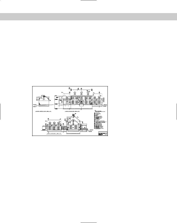
You need to consider the fact that your drawing will most likely be plotted onto a standard paper (sheet) size. The standard orientation for drafting (and the default for most plotters) is landscape orientation, meaning that as you look at the drawing, the paper is wider than it is tall. Figure 5-3 shows an example. These conventions have carried over from the days of hand drafting. (In a computer program, this is not really necessary, because you can rotate the drawing when you plot it.) To scale a drawing onto a piece of paper in a pleasing manner requires a rectangular shape that somewhat resembles the proportions of standard paper sizes.
Figure 5-3: Drawings are usually oriented horizontally, as in this example.
Thanks to Henry Dearborn, AIA, Fairfield, Iowa, for this drawing, which I have altered somewhat.
In addition, although you specify the scale at plotting time, it helps to be aware of the scale you’ll use when plotting your drawing at the outset. The scales used for Geographic Information Systems (GIS), where you might be drawing an entire county, will be different from those used when drawing a house. The scales used in mechanical drafting are again totally different. In fact, in mechanical drafting, if you’re drawing a very small object, such as a 2-inch screw-plate, you might scale up (that is, enlarge the drawing when plotting).
One important reason for establishing the scale at the beginning is to ensure that text, whether annotations or dimensions, is readable in its final plotted form. Applying a scale ensures that text remains a reasonable size even as the rest of the drawing is scaled up or down. Scale also affects linetypes that contain dots or dashes.

Chapter 5 Setting Up a Drawing |
87 |
Some drawings are not scaled. Examples are electrical or electronic schematics, piping diagrams, and railroad schematics. These drawings are representations of electrical or electronic connections but do not resemble the actual physical object that will eventually be created from the drawing. These drawings can be any size as long as they are clear and organized.
Cross- |
You can lay out various views of your drawing on an imaginary piece of paper, called a paper |
Reference |
space layout, to prepare it for plotting. See Chapter 17 for more on layouts and plotting. |
|
When determining your scale to fit a drawing on a sheet of paper, be aware that a plotter cannot print on the entire sheet. A certain amount of the margin around the edge is not available for drawing. Plotters differ in this respect. The plotter’s manual can let you know the width of this unprintable margin. On average, you can assume a half-inch margin on each side; thus you should subtract 1 inch from both the length and width sheet measurements to determine the actual drawing space. Table 5-3 shows standard U.S. sheet sizes.
Table 5-3: Standard Paper Sheet Sizes in the United States (in inches)
Size |
Width |
Height |
Size |
Width |
Height |
|
|
|
|
|
|
A |
11 |
81⁄2 |
D |
34 |
22 |
B |
17 |
11 |
E |
44 |
34 |
C |
22 |
17 |
|
|
|
|
|
|
|
|
|
Table 5-4 lists standard metric sheet sizes.
Table 5-4: Standard Metric Paper Sheet Sizes (in millimeters)
Size |
Width |
Height |
Size |
Width |
Height |
|
|
|
|
|
|
A4 |
297 |
210 |
A1 |
841 |
594 |
A3 |
420 |
297 |
A0 |
1,189 |
841 |
A2 |
594 |
420 |
|
|
|
|
|
|
|
|
|
Scale formats
A scale is often indicated in the format plotted size=actual size. Because you draw at actual size, the actual size is also the drawing size. For example, a scale of 1⁄4"=1' means that 1⁄4 inch on the drawing, when plotted out on a sheet of paper, represents 1 foot in actual life — and in the drawing. This is a typical architectural scale. A windowpane one foot wide would appear 1⁄4-inch wide on paper.

88 |
Part I AutoCAD and AutoCAD LT Basics |
From the scale, you can calculate the scale factor. You use the factor when you set the size for text (see Chapter 13) or for dimensions (see Chapter 15). To do this, the left side of the scale equation must equal 1, and the two numbers must be in the same measurement (for example, both in inches). This requires some simple math. For 1⁄4"=1', you would calculate as follows:
1⁄4"=1'
1"=4' |
Both sides of the equation multiplied by 4 |
1"=48" 4' converted to 48"
Therefore, the scale factor is 48. This means that the paper plot is 1⁄48 of real size.
In mechanical drawing, you might draw a metal joint that is actually 4 inches long. To fit it on an 81⁄2-x-11-inch sheet of paper, you could use a 2"=1" scale, which means that 2" on the paper drawing equals 1" in actual life and the drawing. Calculate the scale factor:
2"=1"
1"=1⁄2"
The scale factor is 1⁄2. This means that the paper plot is twice the real size.
Most professions use certain standard scales. Therefore, you do not usually have a choice to pick any scale you want, such as 1":27'. Instead, the conventions of your profession, client, or office dictate a choice of only a few scales. Table 5-5 lists some standard architectural scales.
Table 5-5: Typical Architectural Scales
Scale Factor |
Plotted Size |
Drawing/Actual Size |
|
|
|
480 |
1/40" |
1' |
240 |
1/20" |
1' |
192 |
1/16" |
1' |
96 |
1/8" |
1' |
48 |
1/4" |
1' |
24 |
1/2" |
1' |
16 |
3/4" |
1' |
12 |
1" |
1' |
4 |
3" |
1' |
2 |
6" |
1' |
1 |
1' |
1' |
|
|
|
Civil engineering scales are somewhat different and range to larger sizes — a bridge is bigger than a house — as shown in Table 5-6.

Chapter 5 Setting Up a Drawing |
89 |
Table 5-6: Typical Civil Engineering Scales
Scale Factor |
Plotted Size |
Drawing/Actual Size |
|
|
|
120 |
1" |
10' |
240 |
1" |
20' |
360 |
1" |
30' |
480 |
1" |
40' |
600 |
1" |
50' |
720 |
1" |
60' |
960 |
1" |
80' |
1,200 |
1" |
100' |
|
|
|
Table 5-7 shows some typical metric scales that can be used for any purpose. You would most typically work in millimeters, but these could represent any metric measurement.
Table 5-7: Typical Metric Scales
Scale Factor |
Plotted Size |
Drawing/Actual Size |
|
|
|
5,000 |
1 |
5,000 |
2,000 |
1 |
2,000 |
1,000 |
1 |
1,000 |
500 |
1 |
500 |
200 |
1 |
200 |
100 |
1 |
100 |
75 |
1 |
75 |
50 |
1 |
50 |
20 |
1 |
20 |
10 |
1 |
10 |
5 |
1 |
5 |
1 |
1 |
1 |
|
|
|
Deciding on a scale and sheet size
As soon as you know the size of your drawing and the scale appropriate for your situation, you need to consider the sheet size of the paper that you’ll plot on. Again, you often find that certain factors limit your choices. Your plotter or printer may be limited to certain sheet