

170 Part II Drawing in Two Dimensions
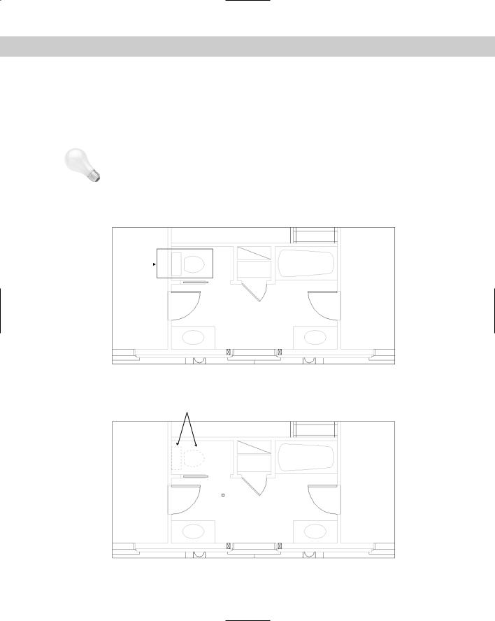
If you select more than one line, CHANGE works differently — it moves the nearest endpoints of all the lines to the change point so that all the lines meet at one point, as shown in Figure 9-12.
Change point
Figure 9-12: Using the CHANGE command on several lines. The original lines are shown as continuous. The new lines, after using the CHANGE command, are dashed.
Changing circles
Changing the radius of a circle has the same result as scaling it. When you select a circle, the command prompts you for a change point. If you pick one, AutoCAD or AutoCAD LT resizes the circle so that it passes through the new point. You can also press Enter. You then get a prompt to enter a new radius.
If you select more than one circle, the command moves from circle to circle, letting you specify a new radius for each, one at a time. You can tell which circle is current because of its drag image, which lets you drag the size of the circle.
If you select more than one circle and try to pick a change point, the command responds with Change point ignored. At that point, one circle becomes active, and you can then pick a change point.
Selecting Objects
If you’ve been following through this chapter’s exercises, you’ve probably thought it tedious to pick several objects one at a time. Imagine trying to individually pick every object in a drawing just to move all the objects one-half unit to the left! Of course, there is a better way. In fact, AutoCAD and AutoCAD LT offer many ways of selecting objects.
Selected objects are also called the selection set of objects.
Selecting objects after choosing a command
When you choose an editing command, you see the Select objects: prompt. This prompt has 16 options — all you could ever want for selecting objects — but these options are not shown on the command line. To specify an option, type the option abbreviation. Because the Select objects: prompt repeats until you press Enter, you can combine options to select objects for any command.
Chapter 9 Editing Your Drawing: Basic Tools |
171 |
In the following list of options, the capitalized letters of the option are the abbreviation you type (uppercase or lowercase letters work) at the Select objects: prompt.
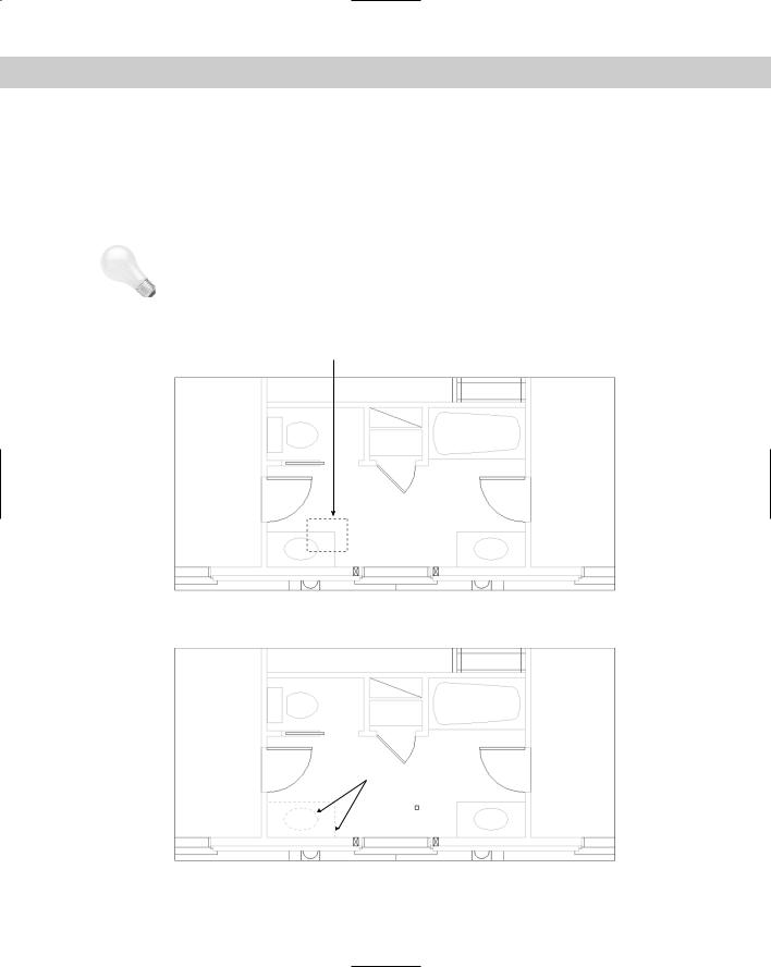
Window: The Window option lets you pick two diagonal corners that define a window. All objects entirely within the window are selected. Figure 9-13 shows the process of picking the window. Figure 9-14 shows the result — the selected objects are highlighted by appearing with dashed instead of continuous lines.
Tip |
You can drag past the edge of the screen (actually the viewport) to specify a window. Hold |
||
|
down the mouse button and continue to move the mouse in the same direction. The display |
||
|
automatically pans so that you can see objects that were off the screen. When you see all the |
||
|
objects you need to select, pick the second corner of the window. |
||
|
Selection window |
||
|
|
|
|
Figure 9-13: Selecting objects with a window. The window selects only objects that lie entirely within the window.
Selected objects
Figure 9-14: The selected objects are highlighted.
172 Part II Drawing in Two Dimensions
Last: The Last option selects the last object that was created and is visible within the current view. Often you create an object and then want to move or copy it. In this situation, the Last option is an easy way to select the object that you just created.
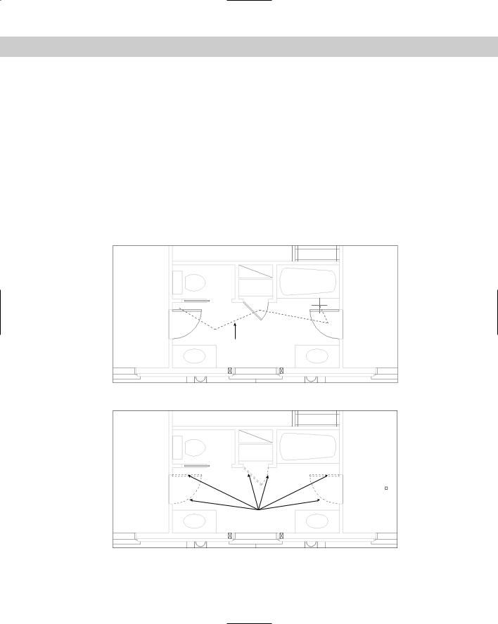
Crossing: Crossing enables you to pick two diagonal corners that define a window. All objects entirely or partly within the window are selected. Figure 9-15 shows the process of picking the window. Figure 9-16 shows the result — the selected objects are highlighted.
Tip |
You can drag past the edge of the screen (actually the viewport) to specify a crossing window. |
|
Hold down the mouse button and continue to move the mouse in the same direction. The |
|
display automatically pans so that you can see objects that were off the screen. After you see |
|
all the objects you need to select, pick the second corner of the crossing window. |
Crossing window
Figure 9-15: Selecting objects with a crossing window. The crossing window selects any objects that lie within or partly within the window.
Selected objects
Figure 9-16: The selected objects are highlighted.
Chapter 9 Editing Your Drawing: Basic Tools |
173 |
BOX: BOX is a combination of Window and Crossing. If you pick the two window corners from left to right, the selection functions as if you used the Window option. If you pick the two points from right to left, the selection functions as if you used the Crossing option. By default, you can select objects this way without specifying the BOX option. See the description of implied windowing later in this chapter.
ALL: The ALL option selects all objects on thawed and unlocked layers in the drawing. (I discuss layers in Chapter 11.) Use the ALL option when you want to select everything, including objects that you can’t currently see on the screen.
Fence: The Fence option enables you to specify a series of temporary lines to select any object crossing the lines. Figure 9-17 shows the process of defining a selection fence. Figure 9-18 shows the result — the selected objects are highlighted.
WPolygon: The Window Polygon option (WPolygon) is like Window except that you create a polygon instead of a rectangular window. This option selects all objects that lie entirely within the polygon.
Fence
Figure 9-17: Using a fence to select objects.
Selected objects
Figure 9-18: The selected objects are highlighted.

174 Part II Drawing in Two Dimensions
CPolygon: The Crossing Polygon option (CPolygon) is like Crossing except that you create a polygon instead of a rectangular window. This option selects all objects that lie entirely or partly within the window.
Group: The Group option selects a named group of objects. (Chapter 10 covers groups.) If you need to work regularly with a certain set of objects, you can place them in a group and then easily select them with one click.
Remove: The Remove option enables you to deselect objects. After you use this option, all objects you select are deselected and are therefore removed from the selection set. Use the Add option to once again select objects.
Tip |
An alternative to using Remove to deselect objects is to press Shift and deselect objects by |
|
picking or implied windowing. Implied windowing is discussed later in this chapter. |
Add: The Add option sets the selection mode to add options to the selection set. Use Add after using Remove to start selecting objects again.
Multiple: The Multiple option turns off highlighting as you select objects. However, you cannot visually determine which objects are in the selection set.
Previous: Previous automatically selects all objects you selected for the previous command. Objects selected and edited by using grips are not remembered for this option. (The next chapter covers grips.)
Undo: Undo deselects the object(s) selected at the last Select objects: prompt. (If you removed objects from the selection set at the last Select objects: prompt, Undo reselects them.)
AUto: AUto combines picking with the BOX option. By default, you can select objects this way without specifying this option. See the description of implied windowing later in this chapter.
Single: When you specify this option, you get another Select objects: prompt. You select objects by using any option, and then AutoCAD immediately ends the selection process. You don’t have to press Enter.
CLass: CLass allows you to select certain objects that were created in another application. Certain applications, such as Autodesk Map, can add a feature classification to an object. Doing so creates an associated classification (XML) file. If you have such an object and the XML file is present, you can select objects by classification property. (AutoCAD only.)
Cycling through objects
It may happen that you have many objects close together in a drawing, making it hard to select the object or point you want. You could always zoom in, but in a complex drawing this can take quite a bit of time. Another trick is to use object cycling. At the Select objects: prompt, hold down Ctrl and pick at the area where more than one object overlaps. The command line displays the <Cycle on> message. One object is highlighted. If it is not the one you want, continue to hold down Ctrl and pick. AutoCAD or AutoCAD LT cycles through the objects. After you have the one you want, release Ctrl. Press Enter to turn object cycling off. You can continue to select other objects or end object selection by pressing Enter.

Chapter 9 Editing Your Drawing: Basic Tools |
175 |
Selecting objects before choosing a command
If you select objects before choosing a command, your options are more limited than if you choose a command first. Nevertheless, you have enough flexibility for most situations. The reason for the limitation is that the Command: prompt is active and anything you might type at the keyboard to indicate a selection option could be confused with a command. You can pick the object to highlight it, use implied windowing, or use the SELECT command to select objects in advance.
The purpose of the SELECT command is simply to select objects. This command then saves these objects for use with the Previous selection option. Choose an editing command and type p at the Select objects: prompt to select the objects you selected with the SELECT command.
Implied windowing
Implied windowing is equivalent to the Auto selection option listed earlier in this chapter. By default, implied windowing is always active. As a result, implied windowing is useful for selecting objects before or after choosing a command. By carefully choosing which way you create a selection window, you determine how you selects objects:
From right to left: If the first window corner is to the right of the second one, you create a crossing window. The crossing window selects all objects that lie entirely or partially within the window.
From left to right: If the first window corner is to the left of the second one, you create a regular selection window. The window selects all objects entirely within the window.
Tip |
You can drag past the edge of the screen (actually the viewport) to specify a window. Hold |
|
down the mouse button and continue to move the mouse in the same direction. The display |
|
automatically pans so that you can see objects that were off the screen. After you see all the |
|
objects you need to select, pick the second corner of the window. |
On the |
The drawing used in the following Step-by-Step exercise on selecting objects, ab09-e.dwg, |
CD-ROM |
is in the Drawings folder on the CD-ROM. |
STEP-BY-STEP: Selecting Objects
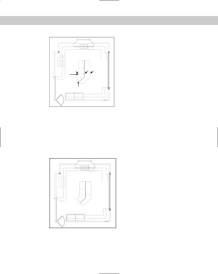
1.Open ab09-e.dwg from the CD-ROM, as shown in Figure 9-19.
2.Save the file as ab09-07.dwg in your AutoCAD Bible folder. Make sure that OSNAP is on. Set running object snaps for endpoint and perpendicular.
3.Draw a line from 1 to 2 in Figure 9-19. You will use this later to illustrate the Last selection option.
4.Type select .
5.To select the six-burner stovetop, pick a point near 3, being careful that the pickbox at the intersection of the crosshairs doesn’t touch any object. Transparently zoom in and back out if necessary. Then move the mouse to 4 and pick again. The objects chosen appear dashed to indicate that they have been selected.
176 Part II Drawing in Two Dimensions
3
|
5 |
4 0 |
1 2 |
9 |
6 |
|
|
|
7 |
|
8 |
Figure 9-19: A kitchen floor plan.
6.To select the last object created, the line drawn in Step 1, type l . It now appears dashed.
7.Turn off OSNAP. To select the interior lines on the kitchen’s island by using a fence, type f . Then pick points 5, 6, and 7. Press Enter to end the fence.
8.Type r at the Select objects: prompt (the prompt changes to Remove objects:) and pick the line at 8 to remove the external island line picked in Step 7. At this point, all the selected items should be dashed, as shown in Figure 9-20.
Figure 9-20: Kitchen floor plan with all selected items shown dashed.
Chapter 9 Editing Your Drawing: Basic Tools |
177 |
9.Press Enter to complete the command.
10.Turn on OSNAP. Start the MOVE command. At the Select objects: prompt, type p
and then press Enter again to end object selection. At the Specify base point or displacement: prompt, pick the endpoint at 9 in Figure 9-20. At the Specify second point of displacement or <use first point as displacement>: prompt, pick the endpoint at 0. All the objects move.
11. Save your drawing.
Customizing the selection process
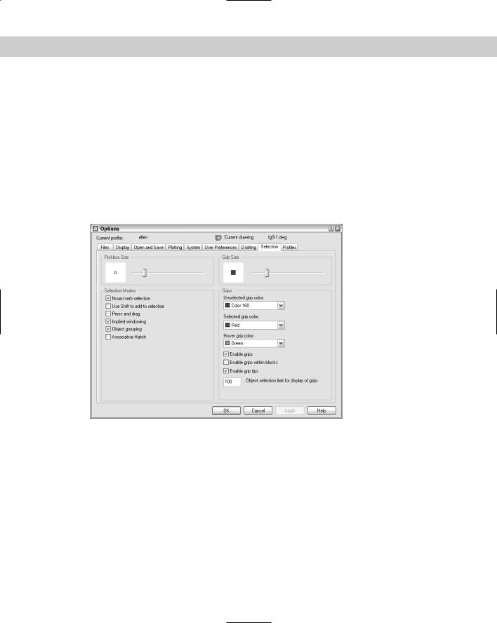
You can customize the way you select objects. To do so, choose Tools Options and click the Selection tab, as shown in Figure 9-21.
Figure 9-21: The Selection tab of the Options dialog box.
Noun/verb selection
As you already know, the editing process consists of two parts — using a command, such as COPY or MOVE, and selecting objects. In AutoCAD/AutoCAD LT lingo, noun means an object in your drawing. Verb refers to a command, because a command acts on an object. This option lets you decide whether you want to be able to select objects before starting a command.
In Windows programs, you typically select objects before starting a command. For example, if you’re using Microsoft Word and want to erase a sentence, you select the sentence first, and then press Del.

178 Part II Drawing in Two Dimensions
By default, noun/verb selection is available, as shown in the first option in the Selection Modes section of the Selection tab in Figure 9-21. With this option enabled, you can select objects first — without giving up the ability to choose commands first. This gives you maximum flexibility.
The advantage of selecting objects first is that, when you switch between Windows programs, you don’t have to change habitual ways of selecting objects. The disadvantage of selecting objects first is that some AutoCAD and AutoCAD LT commands don’t let you select objects first, which can be confusing. Also, when you select objects first, grips appear — sometimes obscuring the objects you need to select.
Use Shift to add to selection
Use Shift to Add to Selection is the second option on the Selection tab of the Options dialog box. By default, this option is not checked. In AutoCAD and AutoCAD LT, you often select more than one object at a time for editing. Therefore, the default is to simply let you select object after object — when you select a second object, the first object stays selected — so that you can easily select any number of objects you want.
However, Windows programs typically enable you to select only one object at a time. To select multiple objects, you need to hold down Shift as you select. Similarly, if you check the Use Shift to Add to Selection option, after selecting one object, you must hold down Shift to select any additional object.
Press and drag
One of the ways to select objects is to create a window that includes a number of objects. You’re already familiar with creating a similar window from using ZOOM with the Window option. If the Press and Drag option is checked, you need to pick at one corner of the window and, without releasing the pick button, drag the cursor to the diagonally opposite corner. This type of action is typical of Windows programs.
By default, this option is not checked, which means that to create a window you pick at one corner of the window, release the mouse button, and pick again at the diagonally opposite corner.
Note |
This setting does not affect ZOOM Window, which always requires two separate picks. |
Implied windowing
By default, this option is on. Implied windowing means that, if you pick any point not on an object, AutoCAD or AutoCAD LT assumes you want to create a selection window. You can then pick the opposite corner to select objects. If you pick the corners from right to left, you get a crossing window. If you pick the corners from left to right, you get a standard selection window. If implied windowing is not on when you pick a point not on an object, the program assumes you missed some object and gives you this message on the command line:
0 found
This option applies only when you have started a command and see the Select objects: prompt. If you turn this option off, you can still enter the Crossing or Window selection options manually (by typing c or w ). When selecting objects before starting the command, implied windowing is always on.

Chapter 9 Editing Your Drawing: Basic Tools |
179 |
Commands and object selection
Certain commands require you to choose objects in a specific order or require objects that have a certain relationship to each other. For example, the TRIM command (covered in the next chapter) requires that you first select an object to trim to (the cutting edge), and then the object to trim. If you selected the objects in advance, the program wouldn’t know which object to trim. Only after you start the TRIM command does AutoCAD or AutoCAD LT know to prompt you exactly for the objects it needs to complete the command. Other commands require that you select objects that are related in some way. The FILLET command (also covered in the next chapter) joins objects that meet — or would meet if extended — by drawing an arc to create a rounded corner. Here again, the command would be meaningless if, say, you selected three or more objects, so the command requires that you use the command first and then specifically prompts you to select the first object and then the second object.
Many commands allow you to select objects first, but the following are some of the most common:
ARRAY |
ERASE |
MOVE |
BLOCK |
EXPLODE |
ROTATE |
CHANGE |
HATCH |
SCALE |
CHPROP |
LIST |
STRETCH |
COPY |
MIRROR |
WBLOCK |
DVIEW |
|
|
These commands enable you to select any number of objects without restriction, so that selecting the objects first and the command second works well.
Object grouping
Creating groups of objects is discussed in the next chapter. Groups are sets of objects that you name. If object grouping is on (the default) when you select one object in a group, all the objects in a group are automatically selected. Object grouping is a global setting; you can also set object grouping on or off for individual groups.
Associative hatch
If checked, Associative Hatch selects boundary objects when you select a hatch within the boundary. This option is off by default. Checking this option is equivalent to setting the PICKSTYLE system variable to 2. Chapter 16 covers hatches.
Pickbox size
In Chapter 4, you read about the aperture, which is the little box at the crosshairs that you use to pick object snaps, such as endpoint or intersection. The pickbox is the box that you see at the intersection of the crosshairs when selecting (or picking) objects. The Pickbox Size area lets you set the size of the pickbox.