


48 |
Part I AutoCAD and AutoCAD LT Basics |
6.Click the Contents tab if it is not on top. Double-click User’s Guide. From the list, double-click The User Interface and then click the plus sign next to Menus, Toolbars, and Tool Palettes.
7.Click Shortcut Menus. Read the text in the right pane.
8.Click the Procedures tab. Click To Display a Shortcut Menu and read the text.
9.On the left side of the Help window, click the Index tab.
10.In the text box at the top, type transparent commands and click Display.
11.From the Topics Found list, double-click Enter Commands on the Command Line.
12.In the right pane, scroll down until you see the heading Interrupt a Command with Another Command or System Variable.
13.Read the text. After you’re done, click the Close button of the Help window.
Summary
In this chapter, you read all you need to know about how to use AutoCAD and AutoCAD LT commands. Specifically, you read about:
Using the menus
Using shortcut menus
Using a dialog box
Working with toolbars
Using the tool palette
Understanding command names
Using and editing the command line
Responding to command options and using the command line and shortcut menus
Repeating commands
Canceling commands
Undoing and redoing commands
Using transparent commands
Using a puck and digitizing tablet to enter commands
Getting help
In the next chapter, I explain how to specify coordinates, an essential skill before you start to draw.
|
|
|
Specifying
Coordinates
Specifying points on the screen is one of the most fundamental tasks in AutoCAD and AutoCAD LT. Unless you know how to spec-
ify a point, you can’t draw anything real, whether a house or a gasket. Most objects you draw have a specific size, and you need to specify that information. Drawing lines, arcs, and circles is accomplished by specifying the coordinates of points on the screen. As with most tasks, AutoCAD and AutoCAD LT offer many ways to accomplish this.
Understanding the X,Y
Coordinate System
Remember when you studied geometry and trigonometry in high school? You created graphs by drawing X and Y axes. Then you plotted coordinates on graph paper. AutoCAD and AutoCAD LT work the same way.
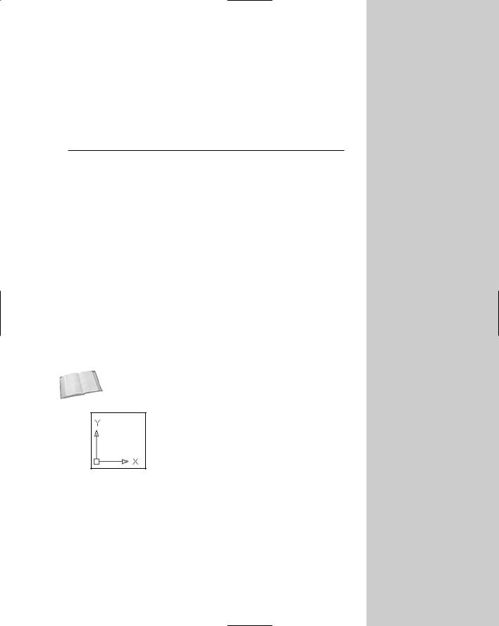
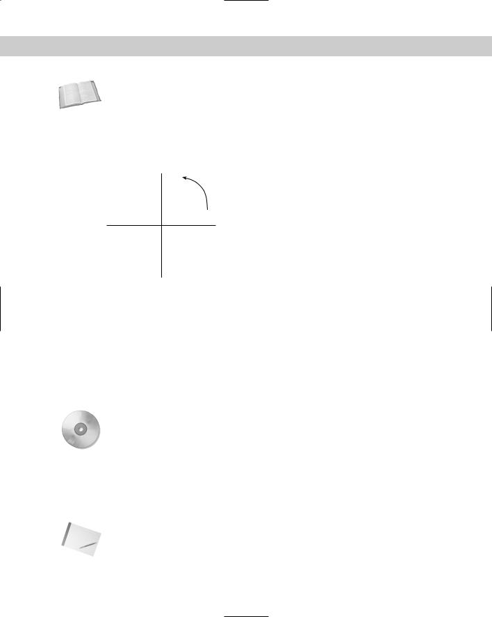
Look at the User Coordinate System (UCS) icon, as shown in Figure 4-1.
Cross- |
The UCS icon can take on different appearances. See Chapter 8 for |
Reference |
details. |
|
Figure 4-1: The UCS icon shows the direction of the X and Y axes.
The arrow marked X points along the X axis in the positive direction. This means that as you go in the direction of the arrow, the X coordinates increase. The arrow marked Y points along the Y axis in the positive direction.
C 4H A P T E R
In This Chapter
Working with absolute, relative, and polar coordinates
Using direct distance entry, orthogonal mode, and polar tracking
Using snap settings
Working with object snaps (OSNAPS)
Locating points
50 |
Part I AutoCAD and AutoCAD LT Basics |
Using this system, every point on the screen can be specified using X and Y coordinates. This is called a Cartesian coordinate system.
Cross- |
As explained in Chapter 1, the universal convention is to place the X coordinate first, then a |
Reference |
comma (but no space), and then the Y coordinate. Refer to Figure 1-4 in Chapter 1 for some |
|
|
|
sample coordinates. |
By default, the intersection of the X,Y axes is 0,0. Use negative numbers for points to the left of the X axis or below the Y axis.
Drawing units
What do the coordinates measure? When you draw in AutoCAD or AutoCAD LT, you draw in undefined units. A line from point 3,0 to point 6,0 is three units long. While you’re drawing, these units can be anything — a millimeter, a centimeter, a meter, an inch, a foot, or a mile.
In reality, you should know exactly what the units represent. After all, you don’t want your 36-foot-wide house to end up 36 inches wide!
When you set up a drawing, you specify how units are displayed — for example, whether partial units show as decimal points or fractions. (I cover units in Chapter 5.) However, you don’t actually specify what the units represent until you print or plot your drawing — covered in Chapter 17.
In general, you should draw full size. If you’re drawing a plan for a factory that will be 120 feet long, for example, you create lines with those measurements. On the screen, you can zoom in to see small details or zoom out to see the whole factory, so that you have no reason not to use the actual line lengths. It’s only when you need to print those 120-foot-long lines on a real sheet of paper that you have to specify how to plot out your drawing at a reduced scale.
Types of measurement notation
Users are typically familiar only with the type of notation used in their own field of specialty, whether scientific, architectural, engineering, or whatever. However, you should be at least somewhat familiar with all the major forms of measurement notation.
Note |
If you are using engineering or architectural units, AutoCAD and AutoCAD LT display parts of |
|
inches (fractions) differently than the format you must use to type them in. You must type in |
|
coordinates without any spaces because in AutoCAD a space is equivalent to pressing Enter |
|
and that ends your input. Use a hyphen between whole and partial inches — for example, |
|
3'2-1/2". (You can omit the " after the inches because inches are assumed in engineering |
|
and architectural units if no symbol follows a number.) However, this appears on the status |
|
bar as 3'-2 1/2". This can be confusing because the hyphen is in a different place, and you |
|
see a space between the whole and partial inches. |
Typing Coordinates
One of the more basic ways to specify the location of an object is to type its coordinates using the keyboard. You can enter several types of coordinates. Use the type of coordinates that suit your specific situation.
Chapter 4 Specifying Coordinates |
51 |
Absolute Cartesian coordinates
When you type a line and enter the actual coordinates, such as a line from point 3,2 to 6,9, you are using absolute Cartesian coordinates. Absolute coordinates are measured from 0,0. These coordinates are probably familiar to you from high-school geometry class.
In this exercise, you practice entering absolute Cartesian coordinates.
STEP-BY-STEP: Entering Absolute Cartesian Coordinates
1.Start a new drawing using the acad.dwt or aclt.dwt template.
2.Choose Line from the Draw toolbar. Follow these prompts:
Specify first point: -10,-5 Specify next point or [Undo]: 21,-5 Specify next point or [Undo]: 21,49
Specify next point or [Close/Undo]: -10,49 Specify next point or [Close/Undo]: -10,-5
Specify next point or [Close/Undo]: to end the command.
Most of the lines are off the screen. By default, a new drawing starts with 0,0 at the lower-left corner of your screen; therefore, negative coordinates do not show.
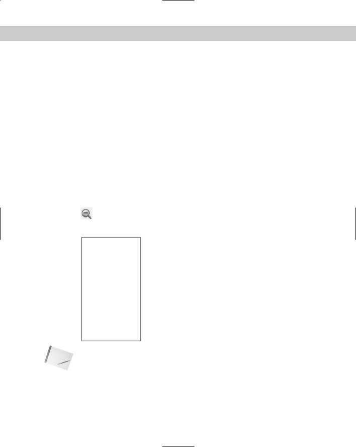
3.Choose Zoom Out from the Zoom flyout on the Standard toolbar. If you still can’t see the entire rectangle, choose Zoom Out again until you can see it. Your picture should look like Figure 4-2.
Figure 4-2: A rectangle drawn by using absolute coordinates.
Note If the prompt responds with Invalid Point or Point or option keyword required, you have entered a coordinate incorrectly. Try typing the coordinate again. Also, don’t forget that you can UNDO a command if you make a mistake. (See Chapter 3 for details.)
52 |
Part I AutoCAD and AutoCAD LT Basics |
4.Start the LINE command again and follow these prompts:
Specify first point: -8,-2
Specify next point or [Undo]: 19,-2 Specify next point or [Undo]: 19,21.5
Specify next point or [Close/Undo]: -8,21.5 Specify next point or [Close/Undo]: -8,-2
Specify next point or [Close/Undo]: to end the command.
5.Once more, start the LINE command and follow these prompts:
Specify first point: -8,22.5
Specify next point or [Undo]: 19, 22.5 Specify next point or [Undo]: 19,46 Specify next point or [Close/Undo]: -8,46 Specify next point or [Close/Undo]: -8,22.5
Specify next point or [Close/Undo]: to end the command.
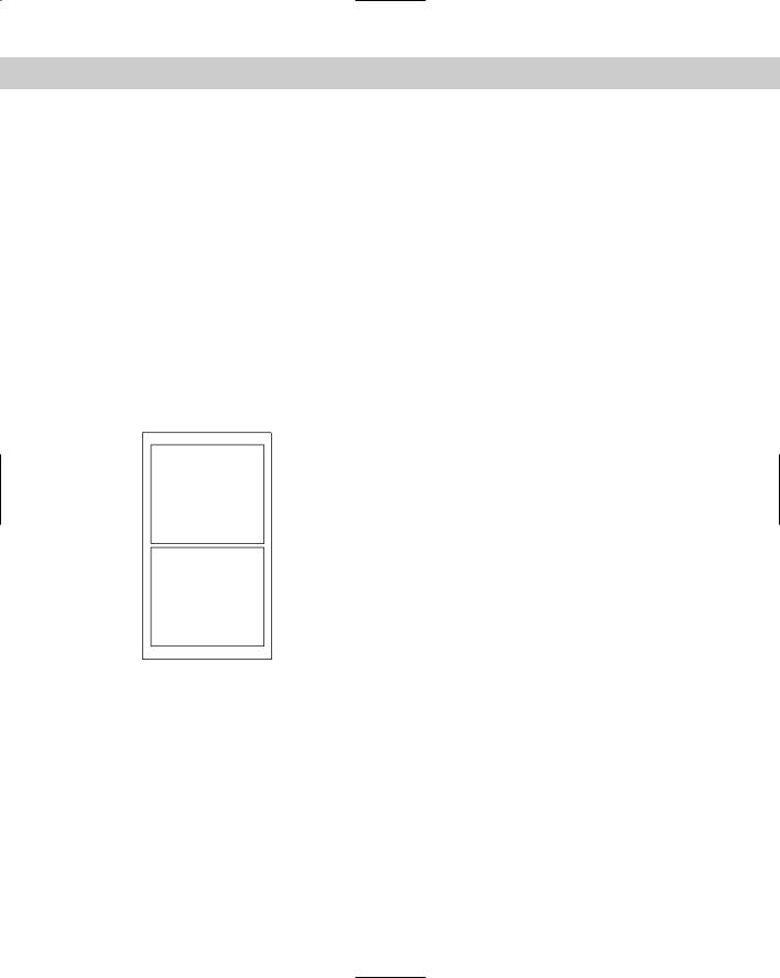
6.Save this drawing in your AutoCAD Bible folder as ab04-01.dwg. You can now see that you’ve drawn a simple window, as shown in Figure 4-3.
Figure 4-3: A window drawn with absolute coordinates.
Two questions may have occurred to you during this exercise. First, isn’t there a better way of entering absolute coordinates? Typing them in is slow and prone to error. Second, how do you know the absolute coordinates for what you’re drawing? Read on for the answers.
Relative Cartesian coordinates
In practice, you usually don’t know the absolute coordinates of the points you need to specify in order to draw an object. Whether you’re drawing an architectural layout, a physical object (as in mechanical drawing), or an electrical schematic, you don’t have X,Y coordinates to work from. However, you often do have the measurements of what you’re drawing. Usually, you start from any suitable point and work from there. In this situation, you know only the length of the lines you’re drawing (if you’re drawing lines). Real life doesn’t have a 0,0 point. Relative coordinates were developed for these situations.
Chapter 4 Specifying Coordinates |
53 |
Relative coordinates specify the X and Y distance from a previous point. They are called relative coordinates because they only have meaning relative to a point previously specified. Suppose that you need to draw a window. You can start the window from any point. From there, you have the measurements you need. (The measurements may be shown on a piece of paper you’re working from, or you may have the actual window sitting next to you so you can measure it.)
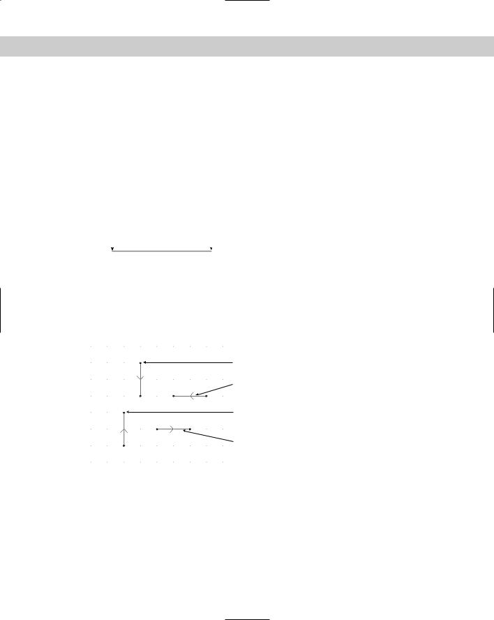
You specify that the coordinates are relative by using the @ symbol. For example, if you start a line by picking any point with the mouse, and you know it should be two units long, you can specify the next point as @2,0. The result is a line starting with the first point you picked and ending two units along the X axis, as shown in Figure 4-4. The line is horizontal because the Y coordinate is 0. In a relative coordinate, this means that the Y distance does not change.
Start point |
End point = @2,0 Figure 4-4: A line whose start point could |
||
|
|
|
be anywhere and whose endpoint is |
|
|
|
|
|
|
|
specified with the relative point @2,0 is a |
|
|
|
horizontal line two units long. |
|
|
|
|
Relative Cartesian coordinates are often used for lines drawn at 90-degree angles (that is, they are either horizontal or vertical). These are called orthogonal lines. When you create a diagonal line from point 3,3 to point @2,5 you don’t know how long the line is.
When you specify a positive number such as the 2 in @2,0, the direction is positive. However, if you want to draw a line in the negative direction of an axis, type a minus sign before the number. Figure 4-5 shows how to draw lines in four directions using relative coordinates.
@0,-2
@-2,0
Figure 4-5: Drawing lines in the four orthogonal directions with relative coordinates. The arrow on each line shows the direction of the line.
@0,2
@2,0
Polar coordinates
Another common situation is to know the distance and angle of a point from either 0,0 or a previous point. In this case, you can use polar coordinates, which can be either absolute or relative. Most commonly, you use relative polar coordinates.
Polar coordinates take the form distance<angle. (To type the angle symbol, use the less than symbol on your keyboard.) Relative polar coordinates must have the @ sign before the coordinate.
54 |
Part I AutoCAD and AutoCAD LT Basics |
Cross- |
Chapter 21 explains more about coordinates in 3D drawings. |
Reference |
|
By default, angles are measured according to the diagram in Figure 4-6, although you can change this system. The positive and negative angles shown next to each other are interchangeable. Use whichever is more meaningful to you.
90 |
Figure 4-6: The standard angle measurement |
-270 |
system. |
180 |
0 |
-180 |
-360 |
270 -90
In the following series of steps, you draw part of a portico, the decorative molding above a door or window. Because it is an architectural design, you use architectural units. In this case, only inches are used, which don’t need to be specified. You can specify feet by using an apostrophe (also called a prime) after any number.
When typing architectural units, partial inches are indicated by fractions in the form 3/4. You need to separate the fraction from the whole inches by a hyphen. This can be a little confusing because the hyphen is also used for negative numbers. For example, to draw a horizontal line of 51⁄4 inches in the negative direction of the X axis, you would type @-5-1/4,0. (The 0 indicates no change in the Y axis because it is a horizontal line.)
On the |
The drawing used in this Step-by-Step exercise on using relative and polar coordinates, |
CD-ROM |
ab04-a.dwg, is in the Drawings folder on the CD-ROM. |
STEP-BY-STEP: Using Relative and Polar Coordinates
1.Open ab04-a.dwg from the CD-ROM. As you move your mouse around, notice that the coordinates displayed on the status bar are in architectural units (that is, in feet and inches). If the coordinates are grayed out, click them or press the F6 key.
2.Choose File Save As and save the drawing in your AutoCAD Bible folder as ab04-02.dwg.
Note |
The next steps involve some complex typing. If you get an error message, try typing the coor- |
|
dinate again. If you realize you made a mistake after ending the command, click Undo on the |
|
Standard toolbar. |
Chapter 4 Specifying Coordinates |
55 |
Note
Tip
3.Start the LINE command. Follow these prompts:
Specify first point: Pick any point at the lower-left corner of your
screen.
Specify next point or [Undo]: @0,-3/4 Specify next point or [Undo]: @75-1/4,0 Specify next point or [Close/Undo]: @0,3/4
Specify next point or [Close/Undo]: @-75-1/4,0
Specify next point or [Close/Undo]: to end the command.
4.Start the LINE command again. Follow the prompts:
Specify first point: . This starts the line at the last endpoint you
specified.
Specify next point or [Undo]: @4-3/4,0 Specify next point or [Undo]: @43<40 Specify next point or [Close/Undo]: @43<320
Specify next point or [Close/Undo]: @-2-1/4,0 Specify next point or [Close/Undo]: @39-7/8<140 Specify next point or [Close/Undo]: @39-7/8<220
Specify next point or [Close/Undo]: to end the command.
In this exercise, you draw a line on top of a line, which is not good drawing practice. Later in this chapter and in coming chapters, you learn techniques to avoid this.
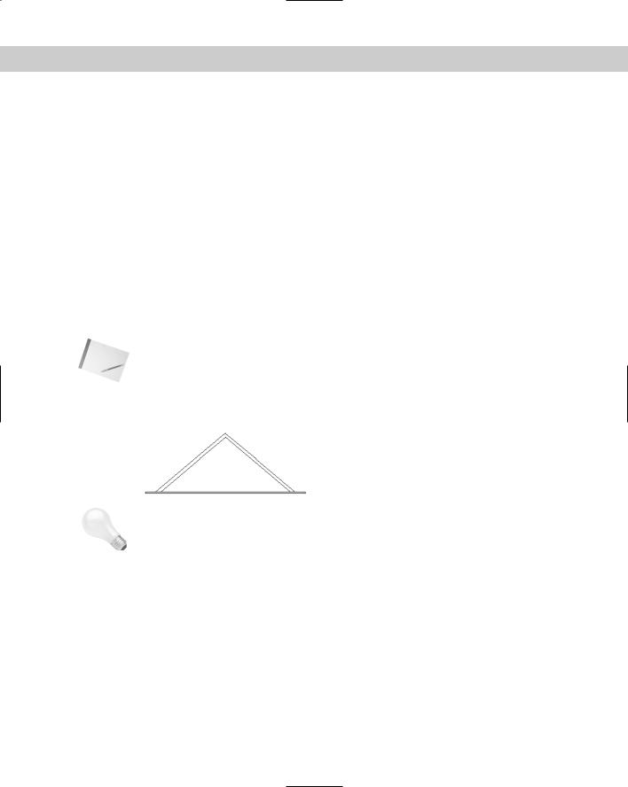
5.Save your drawing. You have created a portion of a portico, which goes over a window of a house, as shown in Figure 4-7.
Figure 4-7: Part of a portico over a window, drawn using relative Cartesian and polar coordinates in architectural notation.
You can type @ at the first prompt of any drawing command to indicate the most recent coordinate specified.
Notice that using relative coordinates, both Cartesian and polar, is much more realistic than using absolute coordinates. However, typing in all those coordinates is still awkward. Typing in coordinates is often the only way to get exactly what you want. Nevertheless, several other techniques for specifying coordinates are easier in many circumstances.
Direct distance entry
One shortcut for entering coordinates is direct distance entry. After you specify the start point of a line, at the Specify next point or [Undo]: prompt, simply move the mouse cursor in the direction you want the line to go and type in the line’s length. It works best in orthogonal mode or with polar tracking (discussed in the following section), which makes specifying exact angles easy.
56 |
Part I AutoCAD and AutoCAD LT Basics |
Note You can use direct distance entry for any command that requires you to specify a distance and a direction, including both drawing and editing commands.
|
Orthogonal mode |
|
Lines drawn at 0, 90, 180, and 270 degrees are called orthogonal lines. When in orthogonal |
|
mode — ortho for short — you can only draw orthogonal lines with the mouse. Ortho mode |
|
also affects editing. For example, with ortho mode on, you can only move objects vertically or |
|
horizontally. Combined with snap and grid, ortho mode makes drawing easier and more effi- |
|
cient. Ortho mode is also great for direct distance entry. |
|
Click ORTHO on the status bar to toggle ortho mode on and off. You cannot have polar track- |
|
ing on at the same time that ortho mode is on. Polar tracking is discussed next. |
Note |
Orthogonal mode only affects points picked directly on the screen by using your mouse. Any |
|
relative or absolute coordinates that you type on the command line override orthogonal |
|
mode. |
Polar tracking
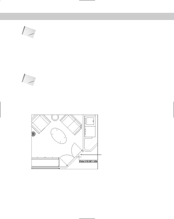
Polar tracking guides you, using a tooltip and vector line, when you want to draw (or edit) at an angle other than the four orthogonal angles, as shown in Figure 4-8. You can use polar tracking for orthogonal angles as well.
Polar tracking vector
 Polar tracking tooltip
Figure 4-8: When polar tracking is on, a tooltip appears when you move the cursor close to one of the polar angles. Here you see a tooltip indicating an angle of 45 degrees.
Polar tracking makes it easy to use direct distance entry to specify distances for many angles. To use polar tracking, you first set the angles that you want to use.
Chapter 4 Specifying Coordinates |
57 |
Setting polar tracking angles
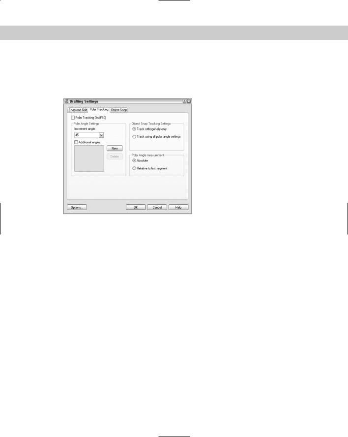
To set the angles, choose Tools Drafting Settings or right-click the POLAR button on the status bar and choose Settings. The Drafting Settings dialog box opens. If necessary, click the Polar Tracking tab, which you can see in Figure 4-9.
Figure 4-9: The Polar Tracking tab of the Drafting
Settings dialog box.
To set polar tracking, you define an increment angle. Polar tracking will then apply to that angle and its multiples. To set the increment angle, click the Increment Angle drop-down arrow, where you can pick from angles that range from every 90 degrees to every 5 degrees. You can also type your own incremental angle in the text box. To add additional angles that you think you’ll need, check Additional Angles, click New, and then type in an angle. You can add up to ten additional angles. Note that additional angles you add are not incremental angles — if you type 35, only 35 degrees will be marked, not 70 degrees or other multiples of 35. To delete an additional angle, select it and click Delete.
On the right side of the dialog box, you can choose how polar tracking works with object snap tracking (covered later in this chapter). You can set object snap tracking to use all the polar angle settings or limit it to orthogonal angles only. You can also set whether polar angles are measured absolutely (relative to 0 degrees) or relative to the segment drawn most recently. By default, absolute angles are used. (AutoCAD LT includes polar tracking but not object snap tracking.)
To turn on polar tracking, check Polar Tracking On on the Polar Tracking tab of the Drafting Settings dialog box. If you are not in the dialog box, press F10 or click the POLAR button on the status bar.
To customize how polar tracking works, click Options in the Drafting Settings dialog box to open the Options dialog box with the Drafting tab on top. The following settings in the AutoTracking Settings section apply to polar tracking:
58 |
Part I AutoCAD and AutoCAD LT Basics |
Display polar tracking vector turns on and off the polar tracking vector, which is the faint dotted line that extends to the end of the screen.
Display AutoTracking tooltip turns on and off the tooltip that tells you the distance and angle. This item in AutoCAD LT is called Display Tracking tooltip.)
Using polar tracking
|
To use polar tracking, you need to move the cursor slowly through the angles to allow time |
|
for the calculation and display of the vector and tooltip. Suppose that you’re drawing a line. |
|
Specify the start point. To specify the second point, move the cursor in the approximate |
|
angle of the line you want to draw. When you see the polar tracking vector and tooltip, leave |
|
the mouse where it is and type the length of the line. Then press Enter to create the line with |
|
the proper length and angle. You’ll find this method easier than typing polar coordinates for |
|
lines with angles specified in your polar tracking settings. |
Tip |
Turn on NumLock on your keyboard and use the numerical pad for typing in lengths. Use the |
|
Enter key on the numerical pad as well. |
You can specify a polar angle for just one command. If you’re drawing a line, after specifying the first point, for example, type the angle preceded by the angle symbol (<). The next segment is then locked to that angle while you type its length. A polar angle specified in this way is called a polar override angle because it overrides the current polar angles in effect. Of course, a polar override is not faster than simply typing a polar coordinate, but it does let you see the angle of the line segment before you type its length.
In the following exercise, you practice using direct distance entry with ortho mode and polar tracking. Before beginning, check that Polar Tracking is set for 45 degrees, as described previously.
On the |
The drawing (ab04-b.dwg) used in the following Step-by-Step exercise on using direct dis- |
CD-ROM |
tance with ortho mode and polar tracking is in the Drawings folder on the CD-ROM. |
STEP-BY-STEP: Using Direct Distance Entry with Ortho Mode and Polar Tracking
1.Open drawing ab04-b.dwg from the CD-ROM.
2.Choose File Save As to save the drawing in your AutoCAD Bible folder as ab04-03.dwg. If ORTHO is not on (that is, if the ORTHO button on the status bar doesn’t look pushed in), click ORTHO.
3.Start the LINE command and, at the Specify first point: prompt, type 2,2 .
4.Move the mouse horizontally to the right and then type .5 .
5.Move the mouse up vertically (in the 90-degree direction) and then type .5 .
6.Move the mouse horizontally to the right and then type 2 . Your drawing should look like Figure 4-10.
7.Move the mouse up in the 90-degree direction and then type .5 .
8.Move the mouse to the left in the 180-degree direction and then type 2 .