

- •Foreword
- •Preface
- •Is This Book for You?
- •How This Book Is Organized
- •How to Use This Book
- •Doing the Exercises
- •Conventions Used in This Book
- •What the Icons Mean
- •About the CD-ROM
- •Other Information
- •Contacting the Author
- •Acknowledgments
- •Contents at a Glance
- •Contents
- •Getting Acquainted with AutoCAD and AutoCAD LT
- •Starting AutoCAD and AutoCAD LT
- •Creating a New Drawing
- •Using the AutoCAD and AutoCAD LT Interface
- •Creating Your First Drawing
- •Saving a Drawing
- •Summary
- •Creating a New Drawing from a Template
- •Working with Templates
- •Opening a Drawing with Default Settings
- •Opening an Existing Drawing
- •Using an Existing Drawing as a Prototype
- •Saving a Drawing Under a New Name
- •Summary
- •The Command Line
- •Command Techniques
- •Of Mice and Pucks
- •Getting Help
- •Summary
- •Typing Coordinates
- •Displaying Coordinates
- •Picking Coordinates on the Screen
- •Locating Points
- •Summary
- •Unit Types
- •Drawing Limits
- •Understanding Scales
- •Inserting a Title Block
- •Common Setup Options
- •The MVSETUP Command
- •Summary
- •Using the LINE Command
- •Drawing Rectangles
- •Drawing Polygons
- •Creating Construction Lines
- •Creating Rays
- •Summary
- •Drawing Circles
- •Drawing Arcs
- •Creating Ellipses and Elliptical Arcs
- •Making Donuts
- •Placing Points
- •Summary
- •Panning
- •The ZOOM Command
- •Aerial View
- •Named Views
- •Tiled Viewports
- •Snap Rotation
- •User Coordinate Systems
- •Isometric Drawing
- •Summary
- •Editing a Drawing
- •Selecting Objects
- •Summary
- •Copying and Moving Objects
- •Using Construction Commands
- •Creating a Revision Cloud
- •Hiding Objects with a Wipeout
- •Double-Clicking to Edit Objects
- •Grips
- •Editing with the Properties Palette
- •Selection Filters
- •Groups
- •Summary
- •Working with Layers
- •Changing Object Color, Linetype, and Lineweight
- •Working with Linetype Scales
- •Importing Layers and Linetypes from Other Drawings
- •Matching Properties
- •Summary
- •Drawing-Level Information
- •Object-Level Information
- •Measurement Commands
- •AutoCAD’s Calculator
- •Summary
- •Creating Single-Line Text
- •Understanding Text Styles
- •Creating Multiline Text
- •Creating Tables
- •Inserting Fields
- •Managing Text
- •Finding Text in Your Drawing
- •Checking Your Spelling
- •Summary
- •Working with Dimensions
- •Drawing Linear Dimensions
- •Drawing Aligned Dimensions
- •Creating Baseline and Continued Dimensions
- •Dimensioning Arcs and Circles
- •Dimensioning Angles
- •Creating Ordinate Dimensions
- •Drawing Leaders
- •Using Quick Dimension
- •Editing Dimensions
- •Summary
- •Understanding Dimension Styles
- •Defining a New Dimension Style
- •Changing Dimension Styles
- •Creating Geometric Tolerances
- •Summary
- •Creating and Editing Polylines
- •Drawing and Editing Splines
- •Creating Regions
- •Creating Boundaries
- •Creating Hatches
- •Creating and Editing Multilines
- •Creating Dlines
- •Using the SKETCH Command
- •Digitizing Drawings with the TABLET Command
- •Summary
- •Preparing a Drawing for Plotting or Printing
- •Creating a Layout in Paper Space
- •Working with Plot Styles
- •Plotting a Drawing
- •Summary
- •Combining Objects into Blocks
- •Inserting Blocks and Files into Drawings
- •Managing Blocks
- •Using Windows Features
- •Working with Attributes
- •Summary
- •Understanding External References
- •Editing an Xref within Your Drawing
- •Controlling Xref Display
- •Managing Xrefs
- •Summary
- •Preparing for Database Connectivity
- •Connecting to Your Database
- •Linking Data to Drawing Objects
- •Creating Labels
- •Querying with the Query Editor
- •Working with Query Files
- •Summary
- •Working with 3D Coordinates
- •Using Elevation and Thickness
- •Working with the User Coordinate System
- •Summary
- •Working with the Standard Viewpoints
- •Using DDVPOINT
- •Working with the Tripod and Compass
- •Getting a Quick Plan View
- •Shading Your Drawing
- •Using 3D Orbit
- •Using Tiled Viewports
- •Defining a Perspective View
- •Laying Out 3D Drawings
- •Summary
- •Drawing Surfaces with 3DFACE
- •Drawing Surfaces with PFACE
- •Creating Polygon Meshes with 3DMESH
- •Drawing Standard 3D Shapes
- •Drawing a Revolved Surface
- •Drawing an Extruded Surface
- •Drawing Ruled Surfaces
- •Drawing Edge Surfaces
- •Summary
- •Drawing Standard Shapes
- •Creating Extruded Solids
- •Drawing Revolved Solids
- •Creating Complex Solids
- •Sectioning and Slicing Solids
- •Using Editing Commands in 3D
- •Editing Solids
- •Listing Solid Properties
- •Summary
- •Understanding Rendering
- •Creating Lights
- •Creating Scenes
- •Working with Materials
- •Using Backgrounds
- •Doing the Final Render
- •Summary
- •Accessing Drawing Components with the DesignCenter
- •Accessing Drawing Content with Tool Palettes
- •Setting Standards for Drawings
- •Organizing Your Drawings
- •Working with Sheet Sets
- •Maintaining Security
- •Keeping Track of Referenced Files
- •Handling Errors and Crashes
- •Managing Drawings from Prior Releases
- •Summary
- •Importing and Exporting Other File Formats
- •Working with Raster Images
- •Pasting, Linking, and Embedding Objects
- •Summary
- •Sending Drawings
- •Opening Drawings from the Web
- •Creating Object Hyperlinks
- •Publishing Drawings
- •Summary
- •Working with Customizable Files
- •Creating Keyboard Shortcuts for Commands
- •Customizing Toolbars
- •Customizing Tool Palettes
- •Summary
- •Creating Macros with Script Files
- •Creating Slide Shows
- •Creating Slide Libraries
- •Summary
- •Creating Linetypes
- •Creating Hatch Patterns
- •Summary
- •Creating Shapes
- •Creating Fonts
- •Summary
- •Working with Menu Files
- •Customizing a Menu
- •Summary
- •Introducing Visual LISP
- •Getting Help in Visual LISP
- •Working with AutoLISP Expressions
- •Using AutoLISP on the Command Line
- •Creating AutoLISP Files
- •Summary
- •Creating Variables
- •Working with AutoCAD Commands
- •Working with Lists
- •Setting Conditions
- •Managing Drawing Objects
- •Getting Input from the User
- •Putting on the Finishing Touches
- •Summary
- •Understanding Local and Global Variables
- •Working with Visual LISP ActiveX Functions
- •Debugging Code
- •Summary
- •Starting to Work with VBA
- •Writing VBA Code
- •Getting User Input
- •Creating Dialog Boxes
- •Modifying Objects
- •Debugging and Trapping Errors
- •Moving to Advanced Programming
- •A Final Word
- •Installing AutoCAD and AutoCAD LT
- •Configuring AutoCAD
- •Starting AutoCAD Your Way
- •Configuring a Plotter
- •System Requirements
- •Using the CD with Microsoft Windows
- •What’s on the CD
- •Troubleshooting
- •Index
266 Part II Drawing in Two Dimensions
Working with Linetype Scales
A noncontinuous linetype is a repeating pattern of dots, dashes, and spaces. Linetypes can also include repeating text or shapes. You may find that the linetype patterns in your drawing are too long or short for clarity. The linetype scale may even be so big or so small that the line looks continuous. How often the pattern is repeated is affected by three factors:
The linetype definition
The global linetype scale
The individual object’s linetype scale
Changing linetype spacing by using a different linetype
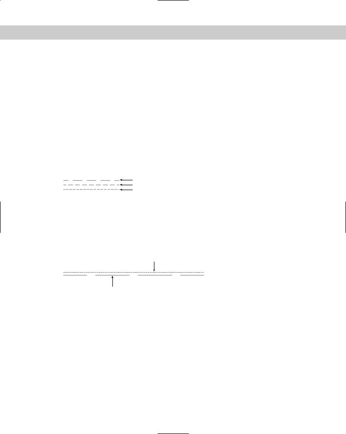
One choice is to change the linetype. A number of linetypes come in short, medium, and long variations, such as Dashedx2, Dashed, and Dashed2, as shown in Figure 11-23.
Dashedx2 |
Figure 11-23: A number of the standard linetypes |
Dashed |
come in three variations, such as Dashedx2, |
Dashed2 |
Dashed, and Dashed2. |
|
AutoCAD’s acad.lin and AutoCAD LT’s aclt.lin contain a number of ISO linetypes that meet the specifications of the International Standards Organization. Your organization or field of specialty may require the use of these linetypes. If so, you should know that the ISO linetype pattern definitions are much longer than the other linetype definitions. Figure 11-24 shows the ISO dash linetype and the regular dashed linetype. You may need to make adjustments to the linetype scale as a result.
Standard dashed linetype
ISO dash linetype
Figure 11-24: A comparison of the regular dashed linetype and the ISO dash linetype.
Changing linetype spacing by changing the global linetype scale
Another choice is to change the global linetype scale, which affects all noncontinuous linetypes in your drawing. AutoCAD and AutoCAD LT multiply the linetype definition by the global linetype scale to calculate the length of each repetition of the linetype:
Linetype scales larger than 1 result in longer sections — and fewer repetitions of the linetype definition per unit.
Linetype scales smaller than 1 result in shorter sections — and more repetitions of the linetype definition per unit.
Chapter 11 Organizing Drawings with Layers, Colors, Linetypes, and Lineweights |
267 |
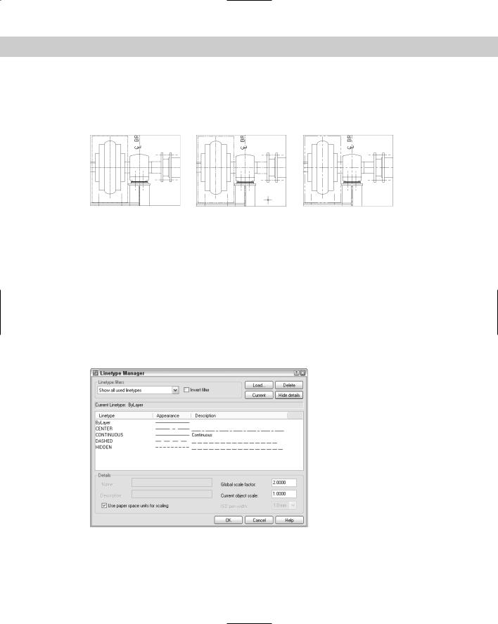
When you change the linetype scale, the drawing regenerates to change all the linetypes. Figure 11-25 shows three versions of a drawing with linetypes at linetype scales of 0.5, 1, and 2. As you can see, a scale of 2 is too large and a scale of 0.5 is too small. A scale of 1 is just right. (Goldilocks would have been happy with it.)
Linetype scale = 0.5 |
Linetype scale = 1 |
Linetype scale = 2 |
Figure 11-25: Three versions of a drawing, using linetype scales of 0.5, 1, and 2.
For purposes of drawing, you simply want to make sure that you can distinguish the linetype both when you can see the entire drawing on the screen and when you zoom in close. The main reason to scale linetypes is for plotting. A linetype scale that works for a drawing of a house on-screen may appear continuous when you plot it at a scale factor of 1=96.
If you want the linetype to appear exactly according to its definition, use the scale factor for the linetype scale. Chapter 5 covers scale factors. If the scale factor doesn’t give you the results you want, try a linetype scale of one-quarter to one-half the scale factor — in the 1=96 example, you might use a linetype scale of 24 or 48.
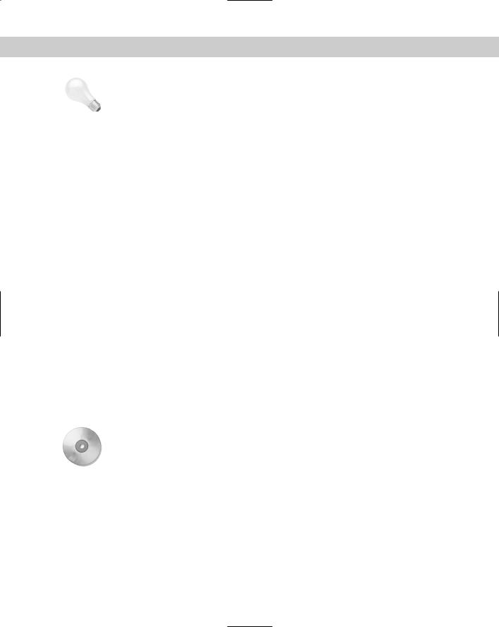
To change the linetype scale, choose Format Linetype to open the Linetype Manager, shown in Figure 11-26. Click Show Details if the lower portion of the dialog box is not displayed.
Figure 11-26: The Linetype Manager dialog box.
In the Global scale factor text box, type the scale factor you want. Click OK. The drawing regenerates, changing the scale of every noncontinuous linetype in the drawing.
268 Part II Drawing in Two Dimensions
Tip |
The global linetype scale is held in the LTSCALE system variable. You can change the linetype |
|
scale by typing LTSCALE at the command line and typing a scale. |
Changing linetype spacing by changing the object linetype scale
On occasion, you may want the linetype spacing to be different for one object — or a small group of objects — only. Perhaps the object is too small to show the linetype pattern or you want to set it off visually. The current object linetype scale works like setting a current color or linetype — all objects drawn after you set the object linetype scale are drawn with the new linetype scale. In most cases, you want to make sure you change the current object linetype scale back to its default of 1 after using it for that one object or group of objects.
Changing the current object linetype scale
To change the linetype scale, choose Format Linetype to open the Linetype Manager, as shown in Figure 11-26. Click Show Details if the lower portion of the dialog box is not displayed. In the Current Object Scale text box, type the scale factor you want. Click OK. Now all objects that you draw use the current object linetype scale.
The current object linetype scale is held in the CELTSCALE system variable. You can also change the current object linetype scale by typing celtscale at the command line and typing in a scale.
If you have also set the global linetype scale to a value other than 1, AutoCAD and AutoCAD LT multiply the two linetype scales to calculate the final result. For example, if you have a global linetype scale of 12 and a current object linetype scale of 0.5, objects you draw will have a resulting linetype scale of 6.
Changing an existing object’s linetype scale
It may be more common to draw an object without setting a special object linetype scale and then decide that you want to change its linetype scale. To change an object’s linetype scale, select the object and choose Properties from the Standard toolbar. In the Properties palette, click Linetype Scale and then type the new linetype scale. This linetype scale only affects the selected object. It does not affect the global linetype scale.
On the |
The drawing used in the following Step-by-Step exercise on changing linetype scales, ab11-e. |
CD-ROM |
dwg, is in the Drawings folder on the CD-ROM. |
STEP-BY-STEP: Changing Linetype Scales
1.Open ab11-e.dwg from the CD-ROM.
2.Save the file as ab11-05.dwg in your AutoCAD Bible folder. This drawing is of a bushing, as shown in Figure 11-27. Notice that the linetype doesn’t show clearly on the short line at 1 and in the small circle at 2.
3.Choose Format Linetype. Click Show Details to open the Details section of the Linetype Manager, if necessary. Change the Global scale factor to 0.5. Click OK. The drawing regenerates. Note that the circles are better, but the short line at 1 still looks like a continuous line.

Chapter 11 Organizing Drawings with Layers, Colors, Linetypes, and Lineweights |
269 |
4.Choose the line at 1. Choose Properties from the Standard toolbar. Click Linetype scale and change it to 0.5. Press Enter. Press Esc to remove the grips and see the result. Notice the difference in the line, which now has a linetype scale of 0.5 (global) times 0.5 (object) = 0.25.
5.Save your drawing. It should look like Figure 11-28.
2
1
Figure 11-27: This drawing of a bushing has two noncontinuous linetypes.
Thanks to Robert Mack of the Dexter Company, Fairfield, Iowa, for this drawing.
Figure 11-28: The drawing’s noncontinuous lines are now more appropriate.
Importing Layers and Linetypes from Other Drawings
The DesignCenter gives you access to drawing content and definitions, such as layers, linetypes, blocks (see Chapter 18), plot layouts (see Chapter 17), and so on that exist in other drawings. I cover the DesignCenter in more detail in Chapter 26, but here I explain how to