

Chapter 7 Drawing Curves and Points 119
You draw some donuts in the next exercise.
Placing Points
Points are generally used for reference. It is sometimes helpful to mark a point that you use later as a guide to place an object or to help you return an object to its original position. When it’s no longer needed, you may erase the point. This is a typical construction method. In some cases, the From object snap or object snap tracking can be used instead of a point.
Cross- |
The DIVIDE and MEASURE commands place point objects along an object. Chapter 12 covers |
Reference |
these commands. |
|
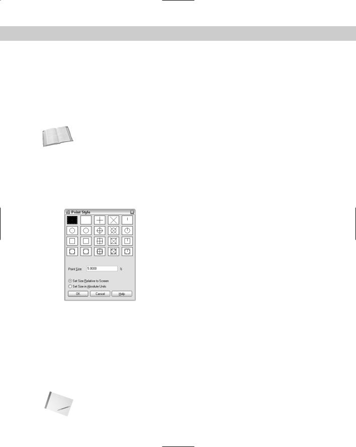
Changing the point style
Different disciplines have different conventions for drawing point objects. As a result, AutoCAD and AutoCAD LT provide 20 types of point styles that you can use in your drawing. Before you draw a point, you should set the point style. You can save this setting in your template.
Choose Format Point Style to open the Point Style dialog box, shown in Figure 7-10.
Figure 7-10: Choosing a point style.
To set the point style, click the box showing the style that you want. Then set the point size, which has the following options:
Set Size Relative to Screen: Use this option if you want the point to always appear the same size, no matter how much you zoom in and out — for example, when you’re using the point as a reference. The size is set as a percentage of the screen. This option is the default, with the size set to 5 percent of the screen.
Set Size in Absolute Units: Use this option if you want the point to have a real size, just like any other object. The size is set in units. Use this option when you want the point to stay the same size relative to other objects in your drawing.
Click OK to close the dialog box.
Note When you change the point style, previously drawn points automatically and immediately change to the new style.
120 Part II Drawing in Two Dimensions
Creating points
After you determine the point style, you’re ready to create points. Choose Point from the Draw toolbar.
You see the following on the command line:
Current point modes: PDMODE=0 PDSIZE=0.0000
Specify a point:
Specify the point you want, either by picking a point on the screen or by typing coordinates. (You can specify a Z coordinate to create a point in 3D space.) You can use object snaps to specify the point. (PDMODE and PDSIZE are system variables for the point style and size, respectively.)
When you choose the POINT command from the Draw toolbar, the command automatically repeats the prompt so that you can continue to specify points. To end the command, press Esc. When you choose Draw Point, you can choose Single Point or Multiple Point from the submenu. The command line version draws single points.
If BLIPMODE is on and you’re using the first point style — a small dot — you cannot see the point until you use the REDRAW command to remove the blips.
Tip |
If you’re using the points for temporary reference, instead of erasing them, you can set the |
|
point style to the second style in the Point Style dialog box (no dot) before plotting. Then |
|
the points do not appear on your plot. |
After you create a point, use the Node object snap to snap to the point. |
|
On the |
The drawing used in the following Step-by-Step exercise on drawing donuts and points, |
CD-ROM |
ab07-d.dwg, is in the Drawings folder on the CD-ROM. |
STEP-BY-STEP: Drawing Donuts and Points
1.Open ab07-d.dwg from the CD-ROM.
2.Save the file as ab07-04.dwg in your AutoCAD Bible folder. The drawing contains a rectangle and connecting wires for an electrical switch. Make sure that OSNAP is on. Set running object snaps for endpoint, quadrant, center, and node.
3.Choose Format Point Style. The Point Style dialog box opens. Choose the third point type, the plus sign. The radio button Set Size Relative to Screen should be marked. The Point Size should be 5.0000%. Choose OK.
4. Choose Point from the Draw toolbar. Follow the prompts:
Specify a point: Use From object snap. (Shift+right-click to open the Object Snap shortcut menu.)
Base point: Use the Endpoint object snap to pick the top-left corner
of the rectangle.
<Offset>: @.08,-.09
Specify a point: Press Esc to complete the command.
Chapter 7 Drawing Curves and Points 121
5.Choose Draw Donut. Follow these prompts:
Specify inside diameter of donut <0.5000>: .04 Specify outside diameter of donut <1.0000>: .06
Specify center of donut or <exit>: Use the Node object snap to pick
the point you drew.
Specify center of donut or <exit>: @.19,0 Specify center of donut or <exit>:
6.Start the POINT command again. Follow the prompts:
Specify a point: Right-click and choose the Mid between 2 points option from the shortcut menu.
First point of mid: _ Use the Center object snap to pick the center of the right-hand donut.(You may have to press Tab until you get the center object snap, and not a quadrant object snap.)
Second point of mid: _Use the Perpendicular object snap and pick the lower horizontal line of the rectangle.
Specify a point: Press Esc.
7.Start the LINE command. Follow the prompts:
Specify first point: Use the Quadrant object snap to pick the right (0 degrees) quadrant of the left donut. If you don’t see the Quadrant SnapTip, press Tab until it appears.
Specify next point or [Undo]: Use the Node object snap to pick the point you just drew. End the LINE command.
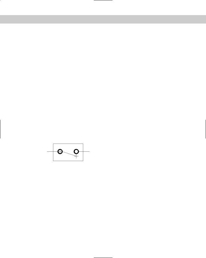
8.Save your drawing. It should look like Figure 7-11.
Figure 7-11: The completed electrical switch. The points show as plus signs.
Summary
In this chapter, you learned how to draw curved objects and points in AutoCAD and AutoCAD LT. You discovered:
All the ways to draw circles
How to define and draw an arc
How to define an ellipse and an elliptical arc
How to draw a donut
How to set the point style and draw points
In the next chapter, you read how to display your drawing for the greatest ease and comfort.
|
|
|


Viewing Your
Drawing
Often you may wish you could zoom in to see a particular part of a drawing more closely or move the display in a certain direc-
tion to reveal an area that was hidden. You may also want to save a view so that you can return to it some other time. In this chapter, you read about controlling the display of your drawing to meet all your drawing needs and increase productivity.
Regenerating and Redrawing
the Display
AutoCAD and AutoCAD LT are vector programs, which means that they store information about objects in your drawing in terms of coordinates and equations. To display your drawing on your computer screen, the programs convert the vector information to pixels. Occasionally, you may need to redisplay the objects on your screen. You can recalculate the entire drawing — called regenerating —
or access a virtual screen in your computer’s memory that can be accessed very quickly — called redrawing. A redraw is much quicker than a regeneration.
When should you use REDRAW and when REGEN?
Use the REDRAW command to remove blips or to quickly refresh the screen. (The REDRAWALL command redraws the display in all viewports. Viewports are covered later in this chapter.) To redraw the screen, choose View Redraw (which actually executes the REDRAWALL command).
Use the REGEN command whenever you want to recalculate the entire drawing. In common usage, the word regen refers
to the REGEN command as well as regenerate or regeneration. To regenerate the entire drawing, type regen at the command line. (REGENALL regenerates all viewports.)
Certain zooms and pans may require a regeneration, which AutoCAD does automatically.
C 8H A P T E R
In This Chapter
Panning and zooming
Using Aerial View to pan and zoom
Working with views
Creating tiled viewports
Creating User
Coordinate Systems
Drawing isometrically