


Chapter 4 Specifying Coordinates |
73 |
most control and flexibility. However, you can change this default to give running object snaps precedence. To change the default, choose Tools Options, click the User Preferences tab, and use the Priority for Coordinate Data Entry section of the dialog box.
Locating Points
Sometimes you need to locate a point that is not on an existing object. For example, you may need a point a certain distance and angle from an existing object. This section explains three techniques that enable you to locate points that are not on objects — object snap tracking, point filters, and the From feature.
Object snap tracking
The purpose of tracking is to let you specify a point based on the object snaps of existing objects. Temporary tracking lines are drawn from points you specify, and you can use PolarSnap or direct distance entry to easily specify new points. Object snap tracking is not available in AutoCAD LT.
Object snap tracking significantly changes the way you draw, offering increased ease and speed of drawing, because it provides visual confirmation of your tracking points. You need to use the keyboard less often, and thus you can do more heads-up drawing. Use the OTRACK button on the status bar to turn object snap tracking on and off.
Object snap tracking can easily handle all of the following tasks and many more:
You’re drawing a line and have specified the start point. You want the endpoint to be exactly vertical to the endpoint of an existing line.
You’re drawing a line and have specified the start point. You want the line to be 3 units long and parallel to an existing line.
You’re drawing a circle inside a rectangle (which could be a hole inside a sheet-metal plate). You want the center of the circle to be exactly centered inside the rectangle, at the intersection of the midpoints of the rectangle’s two sides.
You want to start a line at the point where two existing lines would intersect if they were extended.
To start using object snap tracking, at least one object snap must be active. You can specify an object snap for just that command or turn on a running object snap, as explained in the previous sections. Then click OTRACK on the status bar.
After object snap tracking is on, follow these steps:
1.Start a command that requires you to specify a point.
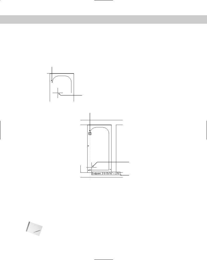
2.Place the cursor briefly over an object snap, such as the endpoint of a line, to temporarily acquire it. You can acquire more than one point. These acquired points are used to calculate the tracking paths. You see a small plus sign (+) over the object snap as confirmation, as shown in Figure 4-25.
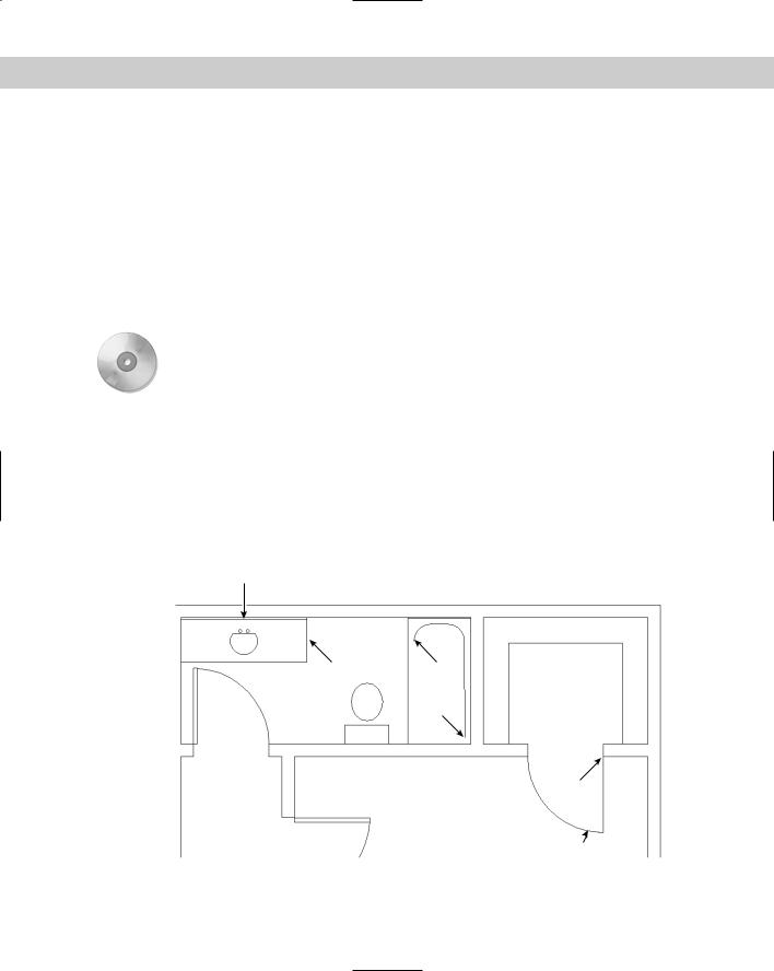
3.Move the cursor away from the object snap toward your desired point. You see the temporary alignment paths as you move the cursor over available drawing paths, as
74 |
Part I AutoCAD and AutoCAD LT Basics |
shown in Figure 4-26. If ORTHO is on, you see only horizontal and vertical paths. If POLAR is on, you see polar paths based on the polar angle settings, as explained earlier in this chapter.
4.When you see a tooltip and a small x, click. You can now continue or complete the command using this point.
Acquired point
Figure 4-25: When you pause over an object snap and then move the cursor slightly, you see a plus sign (+) at the acquired point to show that the point has been acquired and can now be used for object snap tracking.
Cursor
Acquired endpoint of existing arc
Temporary |
|
|
|
|
alignment path |
|
|
|
Cursor |
|
|
|
|
|
Desired endpoint of |
|
|
|
Start point |
|
|
|
of new line |
|
new line (at the "X") |
|
|
|
|
|
||||
|
|
|
Tooltip |
|
|
|
|
|
Figure 4-26: With the endpoint object snap active and ORTHO on, AutoCAD displays temporary alignment paths based on the acquired point.
After you acquire a point, you can clear it in any one of three ways:
Move the cursor back over the point’s plus sign.
Click OTRACK off using the status bar.
Start any new command.
Note Tracking is intended for use in two dimensions only. For 3D point location, use point filters, covered later in this chapter.
Chapter 4 Specifying Coordinates |
75 |
You can customize the following features of object snap tracking on the Drafting tab of the Options dialog box (choose Tools Options):
Uncheck Display Polar Tracking Vector to eliminate the tracking paths.
Uncheck Display Full Screen Tracking Vector to display the tracking paths only from the cursor to the object snap point.
Uncheck Display AutoTrack Tooltip to eliminate the tooltips.
In the Alignment Point Acquisition section, choose Shift to Acquire, which will require you to press Shift to acquire a point when the cursor is over an object snap point.
In the following exercise, you practice locating points with object snap tracking. If you are using AutoCAD LT, skip this exercise, because AutoCAD LT doesn’t have this feature.
On the |
The drawing used in the following Step-by-Step exercise on locating points with object snap |
CD-ROM |
tracking, ab04-c.dwg, is in the Drawings folder on the CD-ROM. |
STEP-BY-STEP: Locating Points with Object Snap Tracking
1.Open ab04-c.dwg from the CD-ROM.
2.Save the drawing as ab04-07.dwg in your AutoCAD Bible folder. This drawing is a section of a simple plan layout of an apartment. Set endpoint and midpoint running object snaps only. Make sure that OSNAP and OTRACK are on and that POLAR is off. ORTHO should also be off.
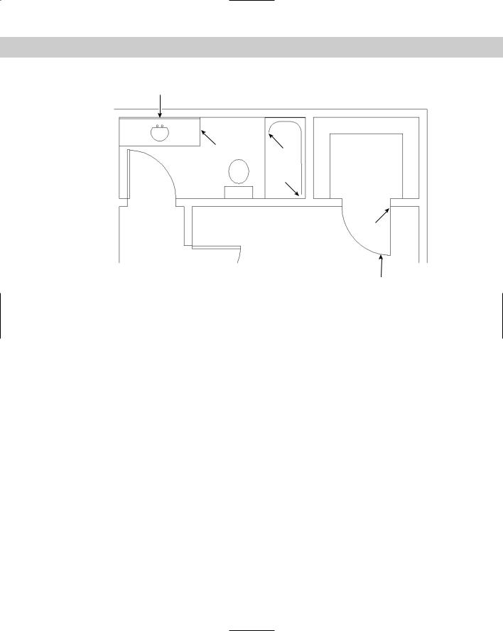
3.Start the LINE command. At the Specify first point: prompt, pick the endpoint at 1 in Figure 4-27. Be sure to pick on the endpoint itself, in order to acquire it.
6
5 2
1
4
3
Figure 4-27: The tub, door, and sink to be completed in this plan layout.
76 |
Part I AutoCAD and AutoCAD LT Basics |
4.At the Specify next point or [Undo]: prompt, pass the cursor over 2. Move the cursor down a little, and you see the small plus sign showing that this endpoint has been acquired.
5.Move the cursor down until it is to the left of 1 and vertical to 2. When you see the tooltip (reading Endpoint: < 270°, Endpoint: < 180°) and the small x marking the intersection of the two points, click to end the line segment.
6.At the Specify next point or [Undo]: prompt, click at 2 and end the LINE command.
7.Start the LINE command again. At the Specify first point: prompt, pick the endpoint of the arc at 3 in Figure 4-27. If you’re not sure that you found the right endpoint, press Tab until the arc is highlighted. Make sure that you’ve acquired the endpoint by clicking the endpoint itself or passing the crosshairs over it.
8.At the Specify next point or [Undo]: prompt, pass the cursor over 4 until you see the small plus sign. Move the cursor to the left until you see the tooltip (reading Endpoint: < 90°, Endpoint: < 180°) and click.
9.At the Specify next point or [Undo]: prompt, pick the endpoint at 4 and end the LINE command.
10.Start the CIRCLE command. At the Specify center point for circle or [3P/2P/ Ttr (tan tan radius)]: prompt, pass the cursor over 5 and then over 6 to acquire both midpoints.
11.Move the cursor to the middle of the sink, where lines from both midpoints would intersect until you see the tooltip (reading Midpoint: < 270° Midpoint: < 180°) and click.
12.At the Specify radius of circle or [Diameter]: prompt, type 7.5 to complete the sink.
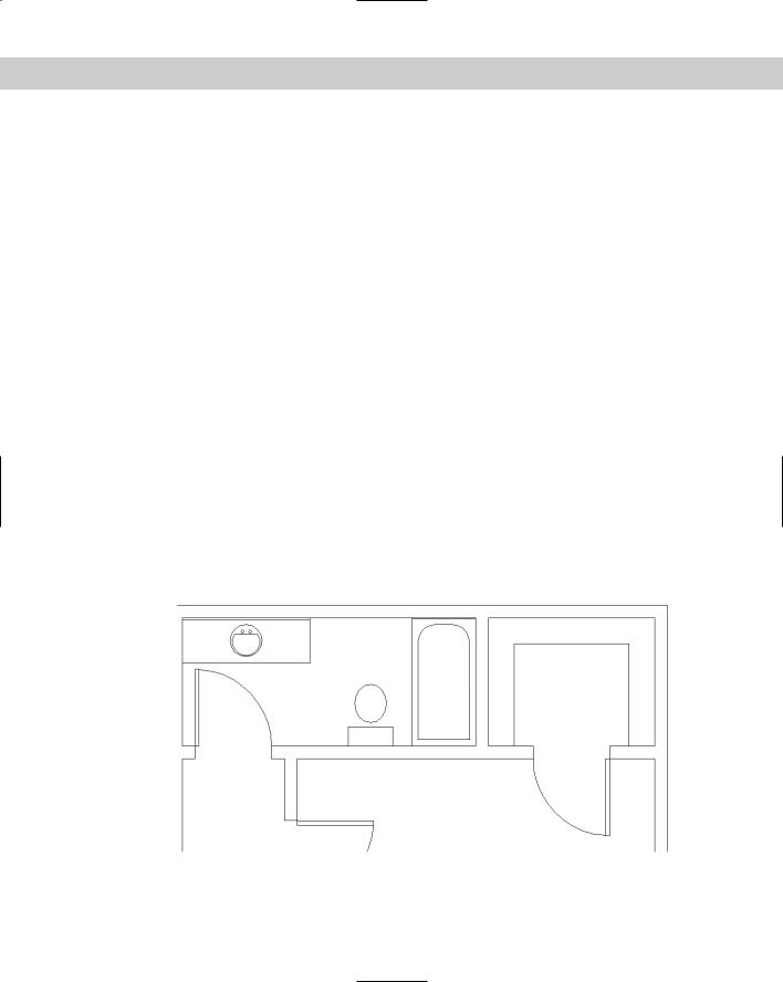
13.Save your drawing. It should look like Figure 4-28.
Figure 4-28: The completed drawing.

Chapter 4 Specifying Coordinates |
77 |
Point filters
Point filters enable you to specify a coordinate using the X coordinate of one existing object snap and the Y coordinate of another. You construct an X,Y coordinate based on coordinates of existing objects. If this sounds complicated, it is. Object snap tracking should mostly eliminate the need to go back to the old point filter way of doing things if you are using AutoCAD. Because object snap tracking isn’t available in AutoCAD LT, you need to use point filters instead. (Point filters have been around for a long time.)
Cross- |
Point filters are often used in 3D drawings where object snap tracking doesn’t work. See |
Reference |
Chapter 21 for more details. |
|
Here’s how to use point filters:
1.Start a command to draw an object.
2.To specify a coordinate, type .x or .y on the command line. You can also find point filters on the object snap shortcut menu (Shift+right-click).
3.The prompt requests a point. Generally, you specify the point by using an object snap.
4.The prompt requests the other coordinate value, which you generally provide by using an object snap. (If you’re working in 2D, ignore the request for a Z coordinate.)
5.Continue your command.
Tip |
You don’t need to use existing coordinates for both the X and Y portions of the coordinate. |
|
For example, you can construct an X,Y coordinate by using the Y coordinate of an existing line |
|
and picking the X coordinate anywhere on the screen. |
In the following exercise, you practice using 2D point filters on the same drawing you used in the previous exercise.
On the |
The drawing used in this Step-by-Step exercise on using 2D point filters, ab04-c.dwg, is in |
CD-ROM |
the Drawing folder of the CD-ROM. |
STEP-BY-STEP: Using 2D Point Filters
1.Open ab04-c.dwg from the CD-ROM.
2.Save the file as ab04-08.dwg in your AutoCAD Bible folder. Make sure that ORTHO and OSNAP are on. If you are using AutoCAD, make sure that OTRACK is off. Set a running object snap for endpoint and midpoint.
3.Start the LINE command.
4.At the Specify first point: prompt, pick the endpoint at 1 in Figure 4-29.
5.At the Specify next point or [Undo]: prompt, type .x . At the of prompt, pick the endpoint at 2 in Figure 4-29.
6.You see the (need YZ): prompt. (Because you’re drawing in 2D, you can ignore the Z.) Choose the endpoint at 1 in Figure 4-29. AutoCAD or AutoCAD LT draws the line segment to the point defined by the X coordinate of 2 and the Y coordinate of 1.
78 |
Part I AutoCAD and AutoCAD LT Basics |
6
5 2
1
4
3
Figure 4-29: Using point filters to specify the start of a line.
7.At the Specify next point or [Undo]: prompt, pick the endpoint at 2. End the LINE command.
8.Start the LINE command again. At the Specify first point: prompt, pick the endpoint at 3. If necessary, press Tab until you see the arc highlighted so you know you have the endpoint of the arc.
9.At the Specify next point or [Undo]: prompt, type .y . At the of prompt, pick the endpoint at 4 in Figure 4-29.
10.At the (need XZ): prompt, pick the endpoint at 3.
11.At the Specify next point or [Undo]: prompt, pick the endpoint at 4. End the LINE command.
12.Start the CIRCLE command. At the Specify center point for circle or [3P/2P/ Ttr (tan tan radius)]: prompt, type .y . At the of prompt, pick the midpoint at 5. At the (need XZ): prompt, pick the midpoint at 6 to place the center of the circle.
13.At the Specify radius of circle or [Diameter]: prompt, type 7.5 .
14.Save your drawing.
From feature
The From feature enables you to create a new object starting at a known distance and direction from an existing object. It’s like creating one or more invisible lines between the existing object and the new object, helping you start the new object in the proper place. Use From when no object snaps are available to help you determine a new point.
Chapter 4 Specifying Coordinates |
79 |
Here’s how to use the From feature:
1.Start a command to draw an object, such as LINE.
2.Press Shift, right-click, and choose From on the shortcut menu. You can also type from on the command line.
3.The prompt requests a base point, which you usually provide by using an object snap, such as an endpoint.
4.The prompt requests an Offset, which you provide by using relative or polar coordinates.
5.Continue the command you started (in Step 1).
In the following exercise, you practice using the From feature.
On the |
The drawing used in the following Step-by-Step exercise on using the From feature, |
CD-ROM |
ab04-06.dwg, is in the Results folder on the CD-ROM. |
STEP-BY-STEP: Using the From Feature
1.Open ab04-06.dwg, which you created in an earlier exercise. If you did not do the previous exercise, open the drawing from the Results folder of the CD-ROM. Make sure ortho mode is on and SNAP is off. OSNAP should be on. Set a running object snap for endpoint.
2.Save the drawing as ab04-09.dwg in your AutoCAD Bible folder.
3.Start the LINE command.
4.From the Object Snap shortcut menu, choose From.
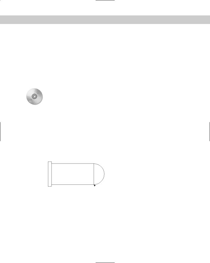
5.The prompt asks you for a base point. Pick the endpoint at 1 in Figure 4-30.
Figure 4-30: Using the From feature to complete the steam boiler.
 1
1
6.At the <Offset>: prompt, type @–1,.5 .
7.You are now ready to continue the line at the Specify next point or [Undo]:
prompt. Press F3 to turn off OSNAP. Move the cursor in the 90-degree direction and type 2 .
8.Move the mouse in the 180-degree direction and type 1 .
9.Move the mouse in the 270-degree direction and type 2 .