204 Part II Drawing in Two Dimensions
4.At the Specify base point or displacement: prompt, pick the endpoint at the bottom-right corner of the garage. At the Specify second point of displacement or <use first point as displacement>: prompt, move the cursor to the right
until you see the polar tracking tooltip. Click when the tooltip says 6'-0"<0. (If you can’t find it, type @6',0 .) This action stretches the garage by 6 feet.
5.Save your drawing. It should look like Figure 10-26.
Figure 10-26: The longer garage.
Using Construction Commands
Three additional commands are commonly used in the process of constructing models. The BREAK command removes sections of objects at points you specify. CHAMFER creates corners, and FILLET creates rounded corners.
Breaking objects
Drawing a long line and then breaking it into two or more shorter lines is often much easier. A common use for BREAK is to break a wall at a door or a window in an architectural floor plan. You specify two points on the object, and the command erases whatever is between those two points. Typically, you use object snaps to specify the points. Sometimes, you can use TRIM to break an object, but if you have no convenient cutting edge, you may find BREAK more efficient.
You can break lines, polylines, splines, xlines, rays, circles, arcs, elliptical arcs, and ellipses.
To break a line, choose Break from the Modify toolbar. You cannot select the object first. The command responds with the Select object: prompt. (Notice that you can only
select one object to break.) At this prompt, you have two choices:
Select the object at one of the break points that you want to create. You then see the
Specify second break point or [First point]: prompt. Because you have already specified the first point, you can now specify the second point. The command breaks the object between the two points.
Chapter 10 Editing Your Drawing: Advanced Tools |
205 |
Select the object by using any method of object selection. You then see the Specify second break point or [First point]: prompt. Right-click and choose First point. At the Specify first break point: prompt, pick the first break point. At the Specify second break point: prompt, pick the second break point. The command breaks the object between the two points.
Tip |
Sometimes you may want to break an object into two pieces at a point, without eras- |
|
ing any part of the object. Use the Break at Point button on the Modify toolbar to help |
|
you easily break an object at a point. After selecting the object, pick where you want to break |
|
the object at the Specify second break point or [First point]: prompt. The two |
|
new objects look the same as before on the screen — until you select one of the objects. To |
|
break objects at a point, AutoCAD and AutoCAD LT use @, which always signifies the last |
|
point entered, to specify the second break point. Thus, the first and second break points are |
|
the same. |
You can use BREAK to shorten an object. Pick one point on the object where you want the new endpoint to be. Pick the other point past its current endpoint to cut off the object at the point you picked on the object.
On the |
The drawing used in the following Step-by-Step exercise on breaking objects, ab10-h.dwg, is |
CD-ROM |
in the Drawings folder on the CD-ROM. |
STEP-BY-STEP: Breaking Objects
1.Open ab10-h.dwg from your CD-ROM.
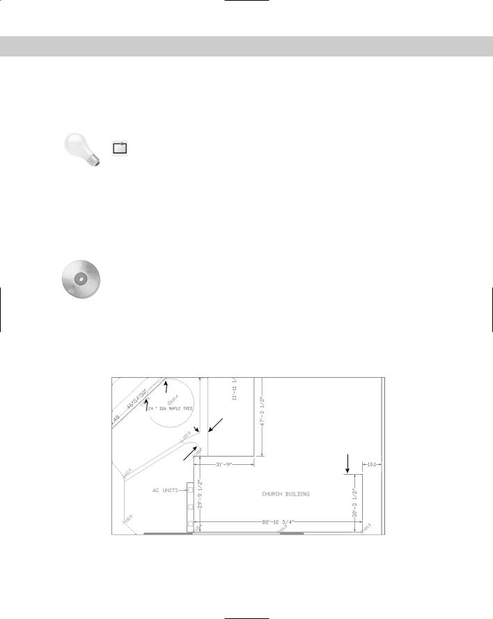
2.Save the file as ab10-09.dwg in your AutoCAD Bible folder. This is a site plan, as shown in Figure 10-27. Turn on OSNAP and set running object snaps for endpoint and intersection.
3
4 5
7
1
6
2
Figure 10-27: A site plan.
206 Part II Drawing in Two Dimensions
3.Choose Break from the Modify toolbar. At the Select object: prompt, pick the line at 1. At the Specify second break point or [First point]: prompt,
pick 2. This action shortens the line.
4.Repeat the BREAK command. At the Select object: prompt, pick the circle (it’s a maple tree) anywhere along its circumference. At the Specify second break point or [First point]: prompt, right-click and choose First point. At the Specify first break point: prompt, pick the intersection at 3. At the Specify second break point: prompt, pick the intersection at 4 to break the circle.
Note |
AutoCAD and AutoCAD LT break circles counterclockwise. If you had picked 4, and then 3, |
|
only the smaller arc would have remained. |
5.Turn on Object Snap Tracking by clicking OTRACK on the status bar.
6.Start the BREAK command again. Follow the prompts:
Select object: Pick the line at 5.
Specify second break point or [First point]: Right-click and choose First point.
Specify first break point: Move the cursor to 6 to acquire it as a tracking point. Then move the cursor to the right onto the line you are breaking. When you see the Endpoint: Intersection tooltip, click. (You have no visual confirmation yet that you picked the right point.)
Specify second break point: Move the cursor to 7 to acquire it as a tracking point. Then move the cursor onto the line you are breaking. At the Endpoint: 4'-2 3/4"<0.0000 tooltip, click.
This action breaks the line.
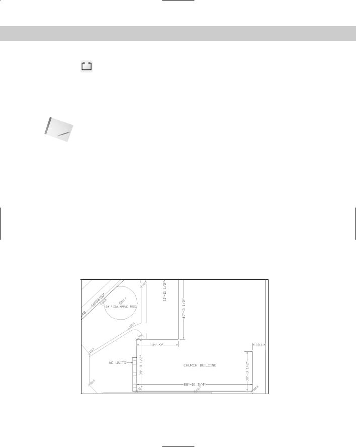
7.Save your drawing. It should look like Figure 10-28.
Figure 10-28: The edited site plan.

Chapter 10 Editing Your Drawing: Advanced Tools |
207 |
On the
CD-ROM
For AutoCAD only: Two AutoLISP programs on the CD-ROM can help you with breaking and unbreaking objects. Pend puts a break line at the end of a pipe. See \Software\Chap10\ Pend. Br draws a line with a break symbol. See \Software\Chap10\Br. The Express Tools contain a command, BREAKLINE, to create a break symbol. Choose Express Draw BreakLine Symbol. Another Express Tools command, OVERKILL (available on the command line) deletes objects that are on top of other objects. For information about installing Express Tools, see Appendix A.
Creating chamfered corners
The CHAMFER command creates corners from two nonparallel lines. You can also chamfer xlines, rays, and polylines. You can simply extend the lines to meet at an intersection (a square corner), or create a beveled edge. If you create a beveled edge, you define the edge by either two distances or one distance and an angle relative to the first line you’re chamfering. Figure 10-29 shows the elements of a chamfered corner.
Second chamfer distance
Second line
Chamfer angle |
First chamfer |
|
|
|
distance |
First line
Figure 10-29: A chamfered corner.
Chamfering is a two-step process. First you define how you want to chamfer the corner, specifying either two distances from the corner or a distance and an angle. Then you select the two lines you want to chamfer. This action chamfers them by using the information you specified.
To chamfer, choose Chamfer from the Modify toolbar. You cannot select objects before the CHAMFER command. The command responds with the (TRIM mode) Current chamfer
Dist1 = 0.0000, Dist2 = 0.0000 Select first line or [Polyline/Distance/ Angle/Trim/Method/mUltiple]: prompt. The command starts by listing the current settings. You can define two distances from a corner or one distance and an angle:
To define two distances from the corner, right-click and choose Distance. At the Specify first chamfer distance <0.0000>: prompt, type the first chamfer distance or press Enter to accept the default (which is the last distance you defined). At the Specify second chamfer distance <0.0000>: prompt, type the second distance. The default for this is always the first chamfer distance because equal chamfer distances are so common.
To define a distance (from the corner) and an angle, right-click and choose Angle. At the Specify chamfer length on the first line <1.0000>: prompt, enter a distance. This is the same as the first chamfer distance. At the Specify chamfer angle from the first line <0>: prompt, type the angle between the first line and the chamfer line.
208 Part II Drawing in Two Dimensions
To extend two nonparallel lines to make a corner, set the chamfer distances to zero and then chamfer the lines. The command extends them to meet. If they already intersect, the command trims them to create a corner. The pick points on intersecting lines should be on the part of the lines that you want to keep (not on the part of the lines you want to trim off).
Now that you specified the settings that you want, you’re ready to chamfer. Your distances or distance and angle are displayed as you just specified them. The command repeats the Select first line or [Polyline/Distance/Angle/Trim/Method/mUltiple]: prompt. Select the first line. If you aren’t creating a chamfer with equal distances, the order in which you select the lines is important. The command trims the first line selected by the first distance and the second line selected based on either the second distance or the angle. At the Select second line: prompt, select the second line to chamfer the lines.
Cross- |
Choose the Polyline option to chamfer an entire polyline at once. Chapter 16 covers polylines. |
Reference |
Chapter 24 discusses chamfering 3D models. |
|
By default, CHAMFER trims the original lines that it chamfers. If you want to keep the full original lines when you add the chamfer line, choose the Trim option and choose No Trim.
Tip |
Use the mUltiple option to continue the prompts and chamfer several corners in one |
|
command. |
On the |
The drawing used in the following Step-by-Step exercise on chamfering lines, ab10-i.dwg, |
CD-ROM |
is in the Drawings folder on the CD-ROM. |
STEP-BY-STEP: Chamfering Lines
1.Open ab10-i.dwg from your CD-ROM.
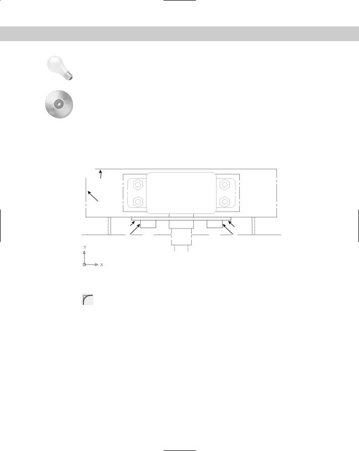
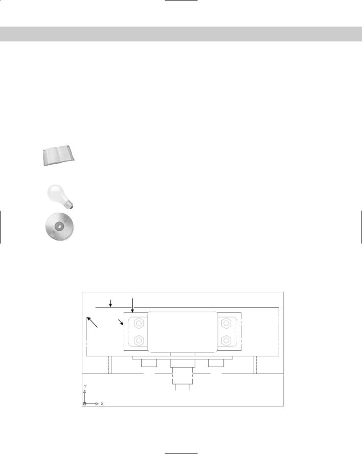
2.Save the file as ab10-10.dwg in your AutoCAD Bible folder. This drawing is a very small section of a “porcupine” mixer, as shown in Figure 10-30.
2 3
4
1
Figure 10-30: A mechanical drawing showing a small section of a “porcupine” mixer.

Chapter 10 Editing Your Drawing: Advanced Tools |
209 |
3.Choose Chamfer from the Modify toolbar. CHAMFER states the current mode and distances. If the distances are not zero, follow these prompts. If they are already
zero, skip to Step 4.
Select first line or [Polyline/Distance/Angle/Trim/Method/mUltiple]:
Right-click and choose Distance from the shortcut menu.
Specify first chamfer distance <1/2>: 0 Specify second chamfer distance <0>:
4.At the Select first line or [Polyline/Distance/Angle/Trim/Method/ mUltiple]: prompt, pick 1 in Figure 10-30. At the Select second line: prompt, pick 2. The command chamfers the two lines to make a corner. (If this doesn’t work, you may have the Trim option set to No Trim. Change the setting to Trim and try again.)
5.Repeat the CHAMFER command. Follow the prompts:
Select first line or [Polyline/Distance/Angle/Trim/Method/mUltiple]:
Right-click and choose Angle.
Specify chamfer length on the first line <1>: 9/16 Specify chamfer angle from the first line <0>: 45
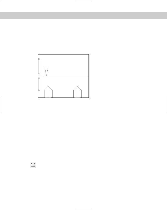
6.At the Select first line or [Polyline/Distance/Angle/Trim/Method/ mUltiple]: prompt, pick 3 in Figure 10-30. At the Select second line: prompt, pick 4. The command chamfers the two lines, as shown in Figure 10-31.
7.Save your drawing.
Figure 10-31: The edited drawing after using the CHAMFER command.
Creating rounded corners
The FILLET command creates rounded corners, replacing part of two lines with an arc. Fillets are often used in mechanical drawings. In certain cases, you can use FILLET instead of the ARC command to create arcs. As with CHAMFER, you can fillet lines, xlines, rays, and polylines — they can even be parallel. You can also fillet circles, arcs, elliptical arcs, and ellipses.