

- •Foreword
- •Preface
- •Is This Book for You?
- •How This Book Is Organized
- •How to Use This Book
- •Doing the Exercises
- •Conventions Used in This Book
- •What the Icons Mean
- •About the CD-ROM
- •Other Information
- •Contacting the Author
- •Acknowledgments
- •Contents at a Glance
- •Contents
- •Getting Acquainted with AutoCAD and AutoCAD LT
- •Starting AutoCAD and AutoCAD LT
- •Creating a New Drawing
- •Using the AutoCAD and AutoCAD LT Interface
- •Creating Your First Drawing
- •Saving a Drawing
- •Summary
- •Creating a New Drawing from a Template
- •Working with Templates
- •Opening a Drawing with Default Settings
- •Opening an Existing Drawing
- •Using an Existing Drawing as a Prototype
- •Saving a Drawing Under a New Name
- •Summary
- •The Command Line
- •Command Techniques
- •Of Mice and Pucks
- •Getting Help
- •Summary
- •Typing Coordinates
- •Displaying Coordinates
- •Picking Coordinates on the Screen
- •Locating Points
- •Summary
- •Unit Types
- •Drawing Limits
- •Understanding Scales
- •Inserting a Title Block
- •Common Setup Options
- •The MVSETUP Command
- •Summary
- •Using the LINE Command
- •Drawing Rectangles
- •Drawing Polygons
- •Creating Construction Lines
- •Creating Rays
- •Summary
- •Drawing Circles
- •Drawing Arcs
- •Creating Ellipses and Elliptical Arcs
- •Making Donuts
- •Placing Points
- •Summary
- •Panning
- •The ZOOM Command
- •Aerial View
- •Named Views
- •Tiled Viewports
- •Snap Rotation
- •User Coordinate Systems
- •Isometric Drawing
- •Summary
- •Editing a Drawing
- •Selecting Objects
- •Summary
- •Copying and Moving Objects
- •Using Construction Commands
- •Creating a Revision Cloud
- •Hiding Objects with a Wipeout
- •Double-Clicking to Edit Objects
- •Grips
- •Editing with the Properties Palette
- •Selection Filters
- •Groups
- •Summary
- •Working with Layers
- •Changing Object Color, Linetype, and Lineweight
- •Working with Linetype Scales
- •Importing Layers and Linetypes from Other Drawings
- •Matching Properties
- •Summary
- •Drawing-Level Information
- •Object-Level Information
- •Measurement Commands
- •AutoCAD’s Calculator
- •Summary
- •Creating Single-Line Text
- •Understanding Text Styles
- •Creating Multiline Text
- •Creating Tables
- •Inserting Fields
- •Managing Text
- •Finding Text in Your Drawing
- •Checking Your Spelling
- •Summary
- •Working with Dimensions
- •Drawing Linear Dimensions
- •Drawing Aligned Dimensions
- •Creating Baseline and Continued Dimensions
- •Dimensioning Arcs and Circles
- •Dimensioning Angles
- •Creating Ordinate Dimensions
- •Drawing Leaders
- •Using Quick Dimension
- •Editing Dimensions
- •Summary
- •Understanding Dimension Styles
- •Defining a New Dimension Style
- •Changing Dimension Styles
- •Creating Geometric Tolerances
- •Summary
- •Creating and Editing Polylines
- •Drawing and Editing Splines
- •Creating Regions
- •Creating Boundaries
- •Creating Hatches
- •Creating and Editing Multilines
- •Creating Dlines
- •Using the SKETCH Command
- •Digitizing Drawings with the TABLET Command
- •Summary
- •Preparing a Drawing for Plotting or Printing
- •Creating a Layout in Paper Space
- •Working with Plot Styles
- •Plotting a Drawing
- •Summary
- •Combining Objects into Blocks
- •Inserting Blocks and Files into Drawings
- •Managing Blocks
- •Using Windows Features
- •Working with Attributes
- •Summary
- •Understanding External References
- •Editing an Xref within Your Drawing
- •Controlling Xref Display
- •Managing Xrefs
- •Summary
- •Preparing for Database Connectivity
- •Connecting to Your Database
- •Linking Data to Drawing Objects
- •Creating Labels
- •Querying with the Query Editor
- •Working with Query Files
- •Summary
- •Working with 3D Coordinates
- •Using Elevation and Thickness
- •Working with the User Coordinate System
- •Summary
- •Working with the Standard Viewpoints
- •Using DDVPOINT
- •Working with the Tripod and Compass
- •Getting a Quick Plan View
- •Shading Your Drawing
- •Using 3D Orbit
- •Using Tiled Viewports
- •Defining a Perspective View
- •Laying Out 3D Drawings
- •Summary
- •Drawing Surfaces with 3DFACE
- •Drawing Surfaces with PFACE
- •Creating Polygon Meshes with 3DMESH
- •Drawing Standard 3D Shapes
- •Drawing a Revolved Surface
- •Drawing an Extruded Surface
- •Drawing Ruled Surfaces
- •Drawing Edge Surfaces
- •Summary
- •Drawing Standard Shapes
- •Creating Extruded Solids
- •Drawing Revolved Solids
- •Creating Complex Solids
- •Sectioning and Slicing Solids
- •Using Editing Commands in 3D
- •Editing Solids
- •Listing Solid Properties
- •Summary
- •Understanding Rendering
- •Creating Lights
- •Creating Scenes
- •Working with Materials
- •Using Backgrounds
- •Doing the Final Render
- •Summary
- •Accessing Drawing Components with the DesignCenter
- •Accessing Drawing Content with Tool Palettes
- •Setting Standards for Drawings
- •Organizing Your Drawings
- •Working with Sheet Sets
- •Maintaining Security
- •Keeping Track of Referenced Files
- •Handling Errors and Crashes
- •Managing Drawings from Prior Releases
- •Summary
- •Importing and Exporting Other File Formats
- •Working with Raster Images
- •Pasting, Linking, and Embedding Objects
- •Summary
- •Sending Drawings
- •Opening Drawings from the Web
- •Creating Object Hyperlinks
- •Publishing Drawings
- •Summary
- •Working with Customizable Files
- •Creating Keyboard Shortcuts for Commands
- •Customizing Toolbars
- •Customizing Tool Palettes
- •Summary
- •Creating Macros with Script Files
- •Creating Slide Shows
- •Creating Slide Libraries
- •Summary
- •Creating Linetypes
- •Creating Hatch Patterns
- •Summary
- •Creating Shapes
- •Creating Fonts
- •Summary
- •Working with Menu Files
- •Customizing a Menu
- •Summary
- •Introducing Visual LISP
- •Getting Help in Visual LISP
- •Working with AutoLISP Expressions
- •Using AutoLISP on the Command Line
- •Creating AutoLISP Files
- •Summary
- •Creating Variables
- •Working with AutoCAD Commands
- •Working with Lists
- •Setting Conditions
- •Managing Drawing Objects
- •Getting Input from the User
- •Putting on the Finishing Touches
- •Summary
- •Understanding Local and Global Variables
- •Working with Visual LISP ActiveX Functions
- •Debugging Code
- •Summary
- •Starting to Work with VBA
- •Writing VBA Code
- •Getting User Input
- •Creating Dialog Boxes
- •Modifying Objects
- •Debugging and Trapping Errors
- •Moving to Advanced Programming
- •A Final Word
- •Installing AutoCAD and AutoCAD LT
- •Configuring AutoCAD
- •Starting AutoCAD Your Way
- •Configuring a Plotter
- •System Requirements
- •Using the CD with Microsoft Windows
- •What’s on the CD
- •Troubleshooting
- •Index

Chapter 12 Getting Information from Your Drawing |
279 |
5.Choose Tools Inquiry Time. Check the current time against your watch. (The command takes the time from your computer’s clock.) Look at the total editing time to see the total time the drawing has been worked on. Press Enter to end the command.
6.Do not save this drawing. Leave the drawing open if you’re going on to the next exercise.
Object-Level Information
Several commands exist solely to provide information about the objects in your drawing.
Listing objects
The LIST command displays information about selected objects. The information displayed depends on the object. For example, the LIST command gives you the radius of a circle and the length of a line.
To list an object, choose Tools Inquiry List. Figure 12-4 shows a typical listing for a line.
Figure 12-4: A typical listing for a horizontal line.
Table 12-2 shows the meaning of the information you receive when you list an object.
|
Table 12-2: LIST Command Information |
|
|
Data |
Comments |
|
|
Layer |
Lists the object’s layer. If the color and linetype are not ByLayer or ByBlock, |
|
AutoCAD lists these as well. |
Space |
Tells you if the object is in model space or paper space. (Chapter 17 covers paper |
|
space.) |
Handle |
Every object in your drawing has a handle. Your drawing’s internal database uses |
|
handles to keep track of objects. |
From point |
Because the example in Figure 12-4 lists a line, it shows the start point. |
To point |
The endpoint of the line. |
Length |
The line’s length. |
Angle in XY Plane |
The line’s angle. This line is horizontal, so its angle is zero. |
Delta X |
The change in the X coordinate from the start point to the endpoint. |
Delta Y |
The change in the Y coordinate from the start point to the endpoint. |
|
|
280 Part II Drawing in Two Dimensions
The Layers and Properties toolbars make it easy to tell an object’s layer, linetype, and color. Remember, when you select an object, its layer, linetype, lineweight, color, and plot style appear in these toolbars. Most of this information is also available from the Properties palette — choose Properties from the Standard toolbar.
Calculating distances
You can easily calculate the distance between any two points by using the DIST command. Choose Tools Inquiry Distance. The command prompts you for two points. You can use any means of specifying a point, although object snaps or snap mode are useful if you want to be sure which point you’re specifying. Here is a typical display for a vertical line:
Distance = 19’-0”, Angle in XY Plane = 270, Angle from XY Plane = 0 Delta X = 0’-0”, Delta Y = -19’-0”, Delta Z = 0’-0”
You can use this information to check dimensions (covered in Chapter 14) or to make calculations that you need for drawing.
Finding coordinates
Finding a coordinate is even easier than calculating a distance. Choose Tools Inquiry ID Point (or just type id ). The ID command prompts you for a point. You can use any means of specifying a point, although object snaps or snap mode are useful. Here is a typical listing:
X = 61’-5 1/8” Y = 32’-4 5/8” Z = 0’-0”
You can use this information to find an absolute coordinate.
On the |
The drawing used in the following Step-by-Step exercise on obtaining object information, |
CD-ROM |
ab12-a.dwg, is in the Drawings folder on the CD-ROM. |
STEP-BY-STEP: Obtaining Object Information
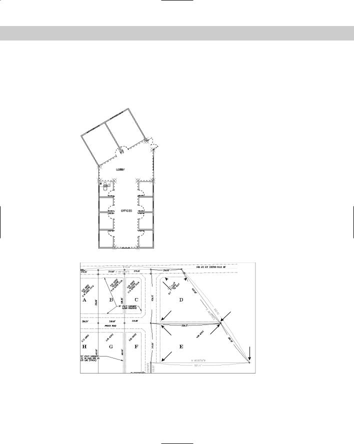
1.Open ab12-a.dwg from the CD-ROM if it isn’t already open from the previous exercise. This is a civil engineering drawing showing several plots of land, as shown in Figure 12-5. OSNAP should be on. Set a running object snap for the endpoint.
2 |
3 |
1
4
Figure 12-5: A civil engineering drawing of several plots of land.

Chapter 12 Getting Information from Your Drawing |
281 |
2.Choose Tools Inquiry List. At the Select objects: prompt, pick 1 in Figure 12-5. Press Enter to end object selection. The result is shown in Figure 12-6. Note the surveyor’s units.
Figure 12-6: The result of using the LIST command on an arc.
3.Choose Tools Inquiry Distance. At the Specify first point: prompt, choose the endpoint at 2 in Figure 12-5, using the endpoint running object snap. At the Specify second point: prompt, choose the endpoint at 3. Here’s the result:
Distance = 2740.90, Angle in XY Plane = N 89d23’34” E, Angle from XY Plane = E
Delta X = 2740.75, Delta Y = 29.05, Delta Z = 0.00
4.Choose Tools Inquiry ID Point. At the Specify point: prompt, pick the endpoint at 4 in Figure 12-5. Here is the result:
X = 6065.67 Y = 3450.58 Z = 0.00
5.Do not save this drawing. Leave the drawing open if you’re going on to the next exercise.
Caution |
The precision set in the Units dialog box (Format Units) affects the results of the LIST, DIST, |
|
and ID commands. See Chapter 5 for more information on the Units dialog box. |
Calculating area and perimeter
You can also calculate the area and perimeter of any area. To start the AREA command, choose Tools Inquiry Area.
You can specify points bounding the area that you want to calculate. The points don’t have to be on an object. The command calculates the area and perimeter as if you had drawn lines between all the points. The command automatically closes the area if you don’t close the area by assuming that the last point is the same as the first point. This option is limited to areas with straight sides.
Instead of picking points, you can use the Object option to calculate the area of objects, which gives you the flexibility to use areas that include curves. Acceptable objects are circles, ellipses, splines, polylines, polygons, regions, and objects created with the 2D SOLID command. (Chapter 16 covers splines, polylines, regions, and solids.) This option calculates an area but adds a length instead of a perimeter. For a circle, you get a circumference. Although a polyline may have the exact same shape as an arc, you cannot calculate the area of an arc. Polylines and splines can be open. In this case the area is calculated as if you had drawn a line from the endpoint to the start point but does not include that last imaginary line when calculating the length.

282 Part II Drawing in Two Dimensions
To calculate the area of irregular shapes, you can keep a running total by using the Add option. Start by specifying the first area. Then use the Add option and specify a second area. The result is the sum of the two areas. You can continue to add areas. You can also use the Subtract option to subtract areas.
Figure 12-7 shows an example of calculating the open area in an office floor plan by picking points. The point objects show the points that were used to calculate the area and perimeter.
Figure 12-7: Calculating the area and perimeter for an office floor plan.
You can also use the BOUNDARY command to create one polyline or region from a complex area. (Chapter 16 covers boundaries and polylines.) You can then use the Object option of the AREA command instead of picking points. However, notice that BOUNDARY included the open doors in the area selected for the office floor plan, as shown in Figure 12-8.
On the |
The drawing used in the following Step-by-Step exercise on using the AREA command, |
CD-ROM |
ab12-a.dwg, is in the Drawings folder on the CD-ROM. |
STEP-BY-STEP: Using the AREA Command
1.Open ab12-a.dwg from the CD-ROM if it isn’t already open from the previous exercise.
2.Use ZOOM Window to zoom in on the parcels of land labeled D and E, as shown in Figure 12-9. OSNAP should be on with a running object snap for endpoint.
3.Choose Tools Inquiry Area.
4.At the Specify first corner point or [Object/Add/Subtract]: prompt, rightclick and choose Add to start Add mode. At the Specify first corner point or [Object/Subtract]: prompt, pick 1 in Figure 12-9 by using the Endpoint running
Chapter 12 Getting Information from Your Drawing |
283 |
object snap. At the Specify next corner point or press ENTER for total (ADD mode): prompt, continue to pick 2, 3, 4, and 5. Press Enter. The command line lists the area and perimeter. (Your figures may be different if you picked different points.)
Area = 123575.16, Perimeter = 1480.17
Total area = 123575.16
Figure 12-8: Using the BOUNDARY command to create an object for use with the AREA command. The boundary is indicated with a dashed line.

 1 2
1 2 5
5
4 3
 6 7
6 7
8
9
Figure 12-9: The AREA command can calculate the area of parcels D and E.
284 Part II Drawing in Two Dimensions
5.At the Specify first corner point or [Object/Subtract]: prompt, pick 6 in Figure 12-9. At the Specify next corner point or press ENTER for total (ADD mode): prompt, pick 7, 8, and 9. Press Enter to complete point selection. The command line reports the area and perimeter of the second area and adds the two areas together to give you the total area. Press Enter again to end the command.
Area = 183399.88, Perimeter = 1884.62 Total area = 306975.04
6.Do not save the drawing. Keep it open if you’re continuing to the next exercise.
Note |
The MASSPROP command is mostly used for 3D drawings, but it can also be used on regions, |
|
which are 2D solid surfaces, such as a shape cut from sheet metal. This command provides |
|
area and perimeter but also other engineering calculations, such as centroids, moments of |
|
inertia, the product of inertia, and so on. Chapter 24 covers this command further. |
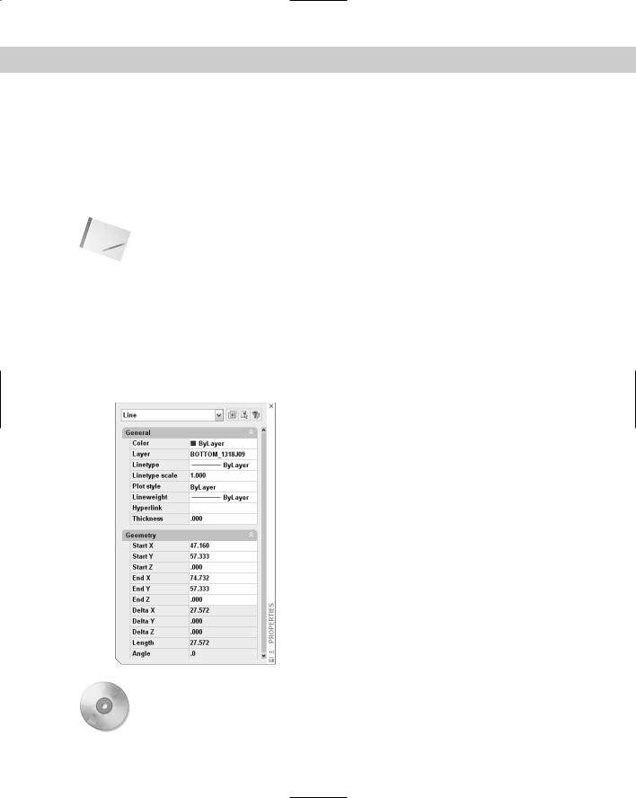
Getting information from the Properties palette
You can also get information about an object by selecting it and choosing Properties from the Standard toolbar. I discuss this Properties palette in Chapter 11 for changing layer, color, linetype, and lineweight properties. As you can see in Figure 12-10, the window also lists the line’s start and end points; delta (change) in X, Y, and Z; length; and angle — much like the LIST command. However, you can change the start and end points directly in this window.
Figure 12-10: The Properties palette lists information about a selected object.
On the |
The CD-ROM contains two routines that provide information about your objects. Linesum |
CD-ROM |
provides the total length of selected lines. Polydis provides the length of a selected poly- |
|
line. Look in the Software\Chap12 folder. |