

- •Foreword
- •Preface
- •Is This Book for You?
- •How This Book Is Organized
- •How to Use This Book
- •Doing the Exercises
- •Conventions Used in This Book
- •What the Icons Mean
- •About the CD-ROM
- •Other Information
- •Contacting the Author
- •Acknowledgments
- •Contents at a Glance
- •Contents
- •Getting Acquainted with AutoCAD and AutoCAD LT
- •Starting AutoCAD and AutoCAD LT
- •Creating a New Drawing
- •Using the AutoCAD and AutoCAD LT Interface
- •Creating Your First Drawing
- •Saving a Drawing
- •Summary
- •Creating a New Drawing from a Template
- •Working with Templates
- •Opening a Drawing with Default Settings
- •Opening an Existing Drawing
- •Using an Existing Drawing as a Prototype
- •Saving a Drawing Under a New Name
- •Summary
- •The Command Line
- •Command Techniques
- •Of Mice and Pucks
- •Getting Help
- •Summary
- •Typing Coordinates
- •Displaying Coordinates
- •Picking Coordinates on the Screen
- •Locating Points
- •Summary
- •Unit Types
- •Drawing Limits
- •Understanding Scales
- •Inserting a Title Block
- •Common Setup Options
- •The MVSETUP Command
- •Summary
- •Using the LINE Command
- •Drawing Rectangles
- •Drawing Polygons
- •Creating Construction Lines
- •Creating Rays
- •Summary
- •Drawing Circles
- •Drawing Arcs
- •Creating Ellipses and Elliptical Arcs
- •Making Donuts
- •Placing Points
- •Summary
- •Panning
- •The ZOOM Command
- •Aerial View
- •Named Views
- •Tiled Viewports
- •Snap Rotation
- •User Coordinate Systems
- •Isometric Drawing
- •Summary
- •Editing a Drawing
- •Selecting Objects
- •Summary
- •Copying and Moving Objects
- •Using Construction Commands
- •Creating a Revision Cloud
- •Hiding Objects with a Wipeout
- •Double-Clicking to Edit Objects
- •Grips
- •Editing with the Properties Palette
- •Selection Filters
- •Groups
- •Summary
- •Working with Layers
- •Changing Object Color, Linetype, and Lineweight
- •Working with Linetype Scales
- •Importing Layers and Linetypes from Other Drawings
- •Matching Properties
- •Summary
- •Drawing-Level Information
- •Object-Level Information
- •Measurement Commands
- •AutoCAD’s Calculator
- •Summary
- •Creating Single-Line Text
- •Understanding Text Styles
- •Creating Multiline Text
- •Creating Tables
- •Inserting Fields
- •Managing Text
- •Finding Text in Your Drawing
- •Checking Your Spelling
- •Summary
- •Working with Dimensions
- •Drawing Linear Dimensions
- •Drawing Aligned Dimensions
- •Creating Baseline and Continued Dimensions
- •Dimensioning Arcs and Circles
- •Dimensioning Angles
- •Creating Ordinate Dimensions
- •Drawing Leaders
- •Using Quick Dimension
- •Editing Dimensions
- •Summary
- •Understanding Dimension Styles
- •Defining a New Dimension Style
- •Changing Dimension Styles
- •Creating Geometric Tolerances
- •Summary
- •Creating and Editing Polylines
- •Drawing and Editing Splines
- •Creating Regions
- •Creating Boundaries
- •Creating Hatches
- •Creating and Editing Multilines
- •Creating Dlines
- •Using the SKETCH Command
- •Digitizing Drawings with the TABLET Command
- •Summary
- •Preparing a Drawing for Plotting or Printing
- •Creating a Layout in Paper Space
- •Working with Plot Styles
- •Plotting a Drawing
- •Summary
- •Combining Objects into Blocks
- •Inserting Blocks and Files into Drawings
- •Managing Blocks
- •Using Windows Features
- •Working with Attributes
- •Summary
- •Understanding External References
- •Editing an Xref within Your Drawing
- •Controlling Xref Display
- •Managing Xrefs
- •Summary
- •Preparing for Database Connectivity
- •Connecting to Your Database
- •Linking Data to Drawing Objects
- •Creating Labels
- •Querying with the Query Editor
- •Working with Query Files
- •Summary
- •Working with 3D Coordinates
- •Using Elevation and Thickness
- •Working with the User Coordinate System
- •Summary
- •Working with the Standard Viewpoints
- •Using DDVPOINT
- •Working with the Tripod and Compass
- •Getting a Quick Plan View
- •Shading Your Drawing
- •Using 3D Orbit
- •Using Tiled Viewports
- •Defining a Perspective View
- •Laying Out 3D Drawings
- •Summary
- •Drawing Surfaces with 3DFACE
- •Drawing Surfaces with PFACE
- •Creating Polygon Meshes with 3DMESH
- •Drawing Standard 3D Shapes
- •Drawing a Revolved Surface
- •Drawing an Extruded Surface
- •Drawing Ruled Surfaces
- •Drawing Edge Surfaces
- •Summary
- •Drawing Standard Shapes
- •Creating Extruded Solids
- •Drawing Revolved Solids
- •Creating Complex Solids
- •Sectioning and Slicing Solids
- •Using Editing Commands in 3D
- •Editing Solids
- •Listing Solid Properties
- •Summary
- •Understanding Rendering
- •Creating Lights
- •Creating Scenes
- •Working with Materials
- •Using Backgrounds
- •Doing the Final Render
- •Summary
- •Accessing Drawing Components with the DesignCenter
- •Accessing Drawing Content with Tool Palettes
- •Setting Standards for Drawings
- •Organizing Your Drawings
- •Working with Sheet Sets
- •Maintaining Security
- •Keeping Track of Referenced Files
- •Handling Errors and Crashes
- •Managing Drawings from Prior Releases
- •Summary
- •Importing and Exporting Other File Formats
- •Working with Raster Images
- •Pasting, Linking, and Embedding Objects
- •Summary
- •Sending Drawings
- •Opening Drawings from the Web
- •Creating Object Hyperlinks
- •Publishing Drawings
- •Summary
- •Working with Customizable Files
- •Creating Keyboard Shortcuts for Commands
- •Customizing Toolbars
- •Customizing Tool Palettes
- •Summary
- •Creating Macros with Script Files
- •Creating Slide Shows
- •Creating Slide Libraries
- •Summary
- •Creating Linetypes
- •Creating Hatch Patterns
- •Summary
- •Creating Shapes
- •Creating Fonts
- •Summary
- •Working with Menu Files
- •Customizing a Menu
- •Summary
- •Introducing Visual LISP
- •Getting Help in Visual LISP
- •Working with AutoLISP Expressions
- •Using AutoLISP on the Command Line
- •Creating AutoLISP Files
- •Summary
- •Creating Variables
- •Working with AutoCAD Commands
- •Working with Lists
- •Setting Conditions
- •Managing Drawing Objects
- •Getting Input from the User
- •Putting on the Finishing Touches
- •Summary
- •Understanding Local and Global Variables
- •Working with Visual LISP ActiveX Functions
- •Debugging Code
- •Summary
- •Starting to Work with VBA
- •Writing VBA Code
- •Getting User Input
- •Creating Dialog Boxes
- •Modifying Objects
- •Debugging and Trapping Errors
- •Moving to Advanced Programming
- •A Final Word
- •Installing AutoCAD and AutoCAD LT
- •Configuring AutoCAD
- •Starting AutoCAD Your Way
- •Configuring a Plotter
- •System Requirements
- •Using the CD with Microsoft Windows
- •What’s on the CD
- •Troubleshooting
- •Index

Chapter 27 Working with Other Applications |
843 |
Working with Raster Images
You can easily import scanned images, digital photographs, and other image files into your drawings. You can use these images to insert a logo, show a photo or artist’s rendering of your model, and for many other uses. Although raster (bitmap) images are generally much larger files than vector drawings, you can easily zoom and pan throughout your drawing. You can usually plot these raster images as well. Table 27-2 shows the raster formats that AutoCAD 2005 supports.
You cannot insert raster images into AutoCAD LT. However, you can open an AutoCAD drawing that contains images and view the image. You can also use the IMAGE command to obtain information about the image. You can copy, move, and resize the image.
Table 27-2: Raster Formats Supported by AutoCAD 2005
File Type |
File Extension |
Comments |
|
|
|
BMP |
.bmp, .dib, .rle |
Windows and OS/2 bitmap |
CALS-1 |
.gp4, .mil, .rst, .cg4, .cal |
Mil-R-Raster 1 |
GIF |
.gif |
CompuServe Graphics Exchange Format |
GeoSPOT |
.bil |
GeoSPOT (used in GIS applications); HDR and PAL |
|
|
files with correlation data must be in the same |
|
|
folder |
JFIF or JPEG |
.jpg, .jpeg |
Joint Photographic Expert Group |
FLIC |
.flc, .fli |
Autodesk Animator FLIC |
IG4 |
.ig4 |
Image Systems Group 4 |
IGS |
.igs |
Image Systems Grayscale |
PCX |
.pcx |
Paintbrush |
PICT |
.pct |
Macintosh picture |
PNG |
.png |
Portable Network Graphic |
RLC |
.rlc |
Run-Length Compressed |
TARGA |
.tga |
True Vision Raster-Based Data Format |
TIF |
.tif, .tiff |
Tagged Image File Format |
|
|
|
Inserting images
It’s easy to insert an image into your AutoCAD drawing. After you insert the image, you can manipulate it in a number of ways. To insert an image, choose Insert Raster Image to open the Select Image File dialog box.

844 Part V Organizing and Managing Drawings
Locate the image you want to insert and choose Open. The Image dialog box (shown in Figure 27-5) opens; this dialog box lets you specify how to insert the image. You can specify the insertion point, scale, and rotation in the dialog box or on-screen. This dialog box is very similar to the Insert dialog box that you use when inserting drawings and blocks.
New |
You can now specify a relative path (instead of the full path) for an image. A relative path |
Feature |
stores only the relationship between the drawing and the image. If you put the image in the |
|
|
|
same folder as the drawing, only the drawing name is stored. Using a relative path and plac- |
|
ing the image in the same folder as the drawing is ideal when you need to share drawings |
|
with people who don’t have the same folder structure as you. |
Figure 27-5: The Image dialog box.
Click Details to open the bottom of the dialog box. Here the dialog box lists the resolution (number of pixels) per drawing unit and the size in pixels, as well as the size in drawing units. The Current AutoCAD Unit is based on the specification in the Units dialog box. (See Chapter 5 for more information.) This information is helpful in deciding how to scale an image.
Note Raster images usually don’t scale up very well. If you enlarge them too much, the dots get too far apart, and the image looks grainy. However, the higher the resolution, the better the image will look when enlarged.
Click OK to insert the image.
You can also use the DesignCenter to insert raster images, as described in Chapter 26.
The Express Tools contain a command, IMAGEEDIT (choose Express File Tools Edit Image), that opens a selected image in a specified image-editing application.
Managing images
As with xrefs, you may need a way to keep track of your images, especially if you insert many of them. Choose Insert Image Manager to open the Image Manager (as shown in Figure 27-6), which enables you to manage the images in your drawing. You can insert images from this dialog box as well.
Chapter 27 Working with Other Applications |
845 |
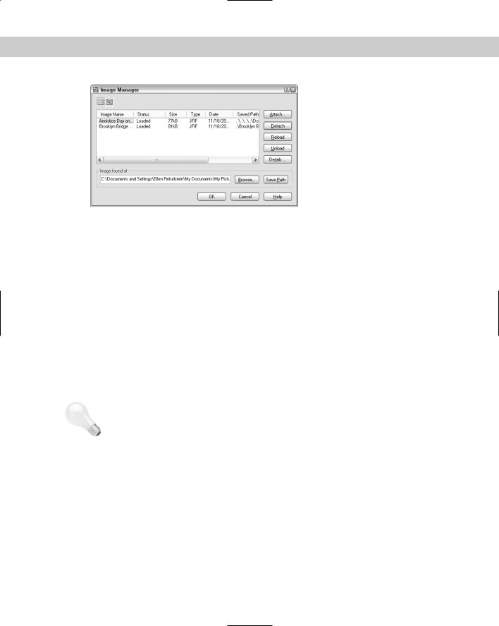
Figure 27-6: The Image Manager.
You can use the List view and Tree view buttons at the top of the dialog box to view your images in a flat list or a hierarchical (tree) format. Here are the other options:
Attach inserts an image, opening the Image dialog box (refer to Figure 27-5).
Detach erases the image from your drawing and deletes all references to it in the drawing database.
Reload redisplays an image after you’ve unloaded it.
Unload removes the display of the image but retains the reference to it. Later, you can reload the image to redisplay it.
Details provides you with a preview, as well as information about the image, its path, and its size.
The Image Found At box shows you the location of the image. If you didn’t save a path when attaching the image, you can do so by clicking Save Path. You can also find an image whose Status shows Not Found by choosing Browse. This would happen if you moved the image after attaching it.
Tip |
You can attach rendered images that you’ve saved as TIF, TGA, or BMP files. A great way to do |
|
this is to create a floating viewport in paper space for the rendered image, letting your clients |
|
see not only the regular drawing but the rendered result on one sheet of paper. (Figure |
|
25-24 in Chapter 25 was created this way.) Remember that you can plot shaded and ren- |
|
dered images. See Chapter 17 for details. |
Clipping images
A powerful feature of AutoCAD lets you clip images just as you clip external references. Large images can slow down your drawing display. You may also simply find it distracting to see parts of an image that you don’t need for your work. For example, if you attach an aerial photograph of a city block but want only one house, being able to clip around the house and not display the rest of the image is a great advantage.

846 Part V Organizing and Managing Drawings
To clip an image, follow these steps:
1.Insert an image.
2.Choose Modify Clip Image.
3.At the Select image to clip: prompt, select the image. Pick the image at its border.
4.At the prompt, press Enter to accept the default of creating a new clipping boundary.
5.At the Enter clipping type [Polygonal/Rectangular] <Rectangular>: prompt, press Enter to create a rectangular clip or right-click and choose Polygonal to create a multisided boundary.
•For a rectangular boundary, pick a first point and the opposite corner to create the boundary.
•For a polygonal boundary, specify the first point and then use the Specify next point or [Undo]: prompt to pick points until you’ve completed the boundary. You can use the Undo option to undo the last pick or the Close option (which appears after you pick three points) to close the final boundary. AutoCAD creates a rubber-band boundary as you pick points so you can see the result. Press Enter when you’re done.
|
At the Enter image clipping option [ON/OFF/Delete/New boundary] <New>: prompt, |
|
you can also use the following options: |
|
Choose ON to turn on a boundary that you previously turned off. |
|
Choose OFF to turn off a boundary and redisplay the entire image. |
|
Choose Delete to delete the clipping boundary. |
Note |
Images are 2D objects. The clipping boundary must be parallel to the plane of the image. For |
|
information on placing images on 3D objects, see the “Mapping” sidebar in Chapter 25. |
Controlling image display
You can control several aspects of image display using the commands detailed in this section. Control the image display to adjust the properties that control how the image looks.
Image display
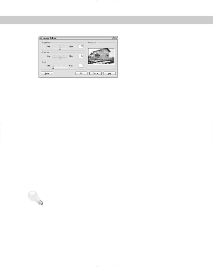
The IMAGEADJUST command lets you change the brightness, contrast and fade of an image. Choose Modify Object Image Adjust to start the IMAGEADJUST command and open the Image Adjust dialog box, shown in Figure 27-7.
This dialog box enables you to dynamically change the brightness, contrast, and fade of the image, using the slider bars or text boxes. You immediately see the results in the preview box. Choose Reset to return the image to its original status.
Chapter 27 Working with Other Applications |
847 |
Figure 27-7: The Image Adjust dialog box.
Image quality
Choose Modify Object Image Quality to start the IMAGEQUALITY command. AutoCAD displays the Enter image quality setting [High/Draft] <High>: prompt. Choose either High or Draft. This command affects the display of all the images in a drawing. Use it when a high-quality image slows down performance. A regen is not necessary after you change this setting. Plotting is always done at high quality.
Image transparency
If the image format you’re using supports transparent pixels, you can use the TRANSPARENCY command to create a transparent background for your image. This works for bi-tonal or grayscale images. (Bi-tonal images have only a foreground and a background color.) By default, transparency is off.
To turn transparency on, choose Modify Object Image Transparency and select the image(s) you want to change. At the Enter transparency mode [ON/OFF] <OFF>: prompt, type on and do a regen. Other objects in your drawing will now be visible through the background of your image.
|
Image frame |
|
The IMAGEFRAME command turns off the frame that surrounds all images in a drawing. |
|
Choose Modify Object Image Frame. Turning off the frame often improves the way the |
|
image looks. However, you select an image by clicking its frame. Therefore, an Off setting |
|
means you cannot select the image, except when using commands specific to images, such |
|
as TRANSPARENCY, IMAGEADJUST, and IMAGECLIP. |
Tip |
Don’t turn the frame off until you’ve finished editing the image. You can also select raster |
|
images using Quick Select. Because raster images are considered to be on the layer that is |
|
active when they’re inserted, you can use Quick Select to select them by layer. |
When an image has a border, the border displays the properties of the layer that was current when the image was inserted. You can use the IMAGEFRAME in AutoCAD LT to turn the frame on and off.

848 Part V Organizing and Managing Drawings
Draw order
The DRAWORDER command (Tools Draw Order) changes the display order of objects, including raster and OLE objects. (OLE is discussed later in this chapter.) This command is very helpful when working with raster and OLE objects, where you may or may not want to hide the other objects in your drawing. You can move an object to the top or bottom or change its order in relation to another object — above or below it. To change an object’s display order, choose Tools Display Order and choose one of the submenu options. At the prompt, select objects. Draw order settings are saved with the drawing.
New
Feature
On the
CD-ROM
You now have more DRAWORDER options. You can bring to front, send to back, bring above object, or send under object. The new TEXTTOFRONT command controls the order of both text and dimensions.
The drawing used in the following Step-by-Step exercise on working with raster images, ab27-b.dwg, and the images ab27-b.tif and ab27-b1.bmp, are in the Drawings folder on the CD-ROM. This exercise works with AutoCAD only.
STEP-BY-STEP: Working with Raster Images
1.Open ab27-b.dwg from the CD-ROM.
2.Save the file as ab27-03.dwg in your AutoCAD Bible folder.
3.Choose View 3D Views Top.
4.Choose Insert Raster Image.
5.In the Select Image File dialog box, choose ab27-b.tif from the CD-ROM. Click Open. Click Details. Notice that the image is 1×0.61 units. Compared to the house, it is tiny.
6.In the Image dialog box, uncheck Specify on-screen for the Scale factor and change the scale factor to 5. Click OK.
7.At the Specify insertion point <0,0>: prompt, pick any point on the left side of the screen. The image is still tiny, but that’s okay. Choose Zoom Window from the Zoom flyout of the Standard toolbar to zoom closely into the image.
8.Choose Modify Object Image Adjust. At the Select image(s): prompt, select the image by picking its frame. Press Enter. In the Image Adjust dialog box, change the Contrast to 60 and the Brightness to 40. Choose OK.
9.Choose Modify Clip Image. At the Select image to clip: prompt, select the image again, which is shown in Figure 27-8. Follow the prompts:
Enter image clipping option [ON/OFF/Delete/New boundary] <New>: Enter clipping type [Polygonal/Rectangular] <Rectangular>: Specify first corner point: If OSNAP is on, turn it off. Pick 1 in Figure 27-8.
Specify opposite corner point: Pick 2.
10.Use Zoom Realtime to zoom out so that you have room to insert another image. Choose Insert Raster Image and attach ab27-b1.bmp (located on the CD-ROM) with a scale factor of 5. Insert it below the first image.
Chapter 27 Working with Other Applications |
849 |
2
1
Figure 27-8: Clipping the raster image.
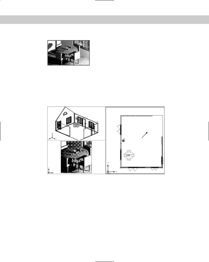
11.Click the Layout1 tab to enter paper space, which has three floating viewports. Click PAPER to enter model space. Click the bottom-left viewport. Choose View 3D Views Top. You should now see the images as a small dot to the left of the house. Use Zoom Window to zoom into the rendered table. Your drawing should now look like Figure 27-9.
1
Figure 27-9: The drawing with a rendered view in one viewport.
12.Click the right viewport. If necessary, pan the house to the right until you can see the two images you attached. Move the Cottonmill Houses image to 1 in Figure 27-9. Scale it, using a base point at its lower-left corner and a scale factor of 25. Move it until it fits nicely in the upper-right corner of the floor plan. Pan again to center the house in the viewport. (If it disappears, do a Zoom Extents.)
13.Choose Modify Object Image Frame. Right-click and choose Off. AutoCAD removes the frames from the two images.
14.Save your drawing.