

180 Part II Drawing in Two Dimensions
Note |
If Noun/Verb Selection is off and grips are disabled, no pickbox appears at the intersection of |
|
the crosshairs until you start an editing command and the command line displays the Select |
|
objects: prompt. However, if either Noun/Verb Selection or grips are on, the pickbox is |
|
always at the crosshairs, letting you select objects at any time. |
Summary
All drawings need to be edited, either as part of the drawing process or to make corrections. In this chapter, you read about:
Erasing objects
Moving objects
Copying objects
Rotating objects
Scaling objects
Using the CHANGE command on lines and circles
The many ways of selecting objects
Customizing the object-selection features
The next chapter covers the more-advanced editing commands and options.
|
|
|

Editing
Your Drawing:
Advanced Tools
This chapter completes the discussion of geometric editing commands — covering the more-complex commands used to refine the details of your drawing. I also discuss grips, which make it easy to move, mirror, rotate, scale, and stretch objects. I explain how to
use the Properties palette to edit objects. I end the chapter with a discussion of three ways to control the selection of objects — groups, filters, and the Quick Select feature.
Copying and Moving Objects
Three commands enable you to copy objects in very specific ways. MIRROR creates a mirror image. ARRAY copies objects in a rectangular or circular pattern. OFFSET creates parallel objects. Although these commands make copies of objects, they produce a result that would be difficult or impossible to produce simply by using the COPY command. The ALIGN command moves objects by aligning them with other objects in the drawing.
Using the MIRROR command
Many drawings have symmetrical elements. Often, especially in mechanical drawing, you can create one-half or one-quarter of a model and complete it simply by mirroring what you have drawn.
To mirror, select an object or objects and then choose Mirror from the Modify toolbar. Alternatively, choose Mirror from the
Modify toolbar and then select an object or objects.
The command prompts for the first and second points of the mirror line. This is an imaginary line across which the command creates the mirrored object. The length of the line is irrelevant — only its start point and direction are important.
10C H A P T E R
In This Chapter
Using advanced copying commands: MIRROR, ARRAY, and OFFSET
Using advanced resizing commands: TRIM, EXTEND, STRETCH, and LENGTHEN
Using construction commands: BREAK, CHAMFER, and FILLET
Creating a revision cloud and a wipeout
Double-clicking to edit objects
Editing objects with grips and the Properties palette
Using selection filters and Quick Select
Creating groups of objects
182 Part II Drawing in Two Dimensions
Tip |
Most mirror lines are orthogonal. Therefore, after you specify the first mirror point, turn on |
|
ORTHO and move the mouse in the direction of the second point. You can then quickly pick |
|
the second point. Polar tracking can also easily guide you to specify an orthogonal mirror line. |
The command then asks if you want to delete the source objects. The source objects are the objects you have selected to mirror. If you want to keep them, type n or press Enter. You keep the source objects when you’re building a symmetrical model and want the mirror image to be added to the original object(s). Type y when you want to edit an object (change its orientation) so that only the mirror image is retained in the drawing.
On the |
The drawing used in the following Step-by-Step exercise on mirroring objects, ab07-02.dwg, |
CD-ROM |
is in the Results folder on the CD-ROM. |
STEP-BY-STEP: Mirroring Objects
1.Open ab07-02.dwg from the Results folder of the CD-ROM. If you completed the exercise on arcs in Chapter 7, you can open this drawing from your AutoCAD Bible folder.
2.Save the file as ab10-01.dwg in your AutoCAD Bible folder. Make sure OSNAP is on. Set a running object snap for intersections only.
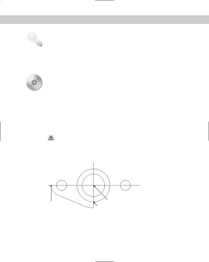
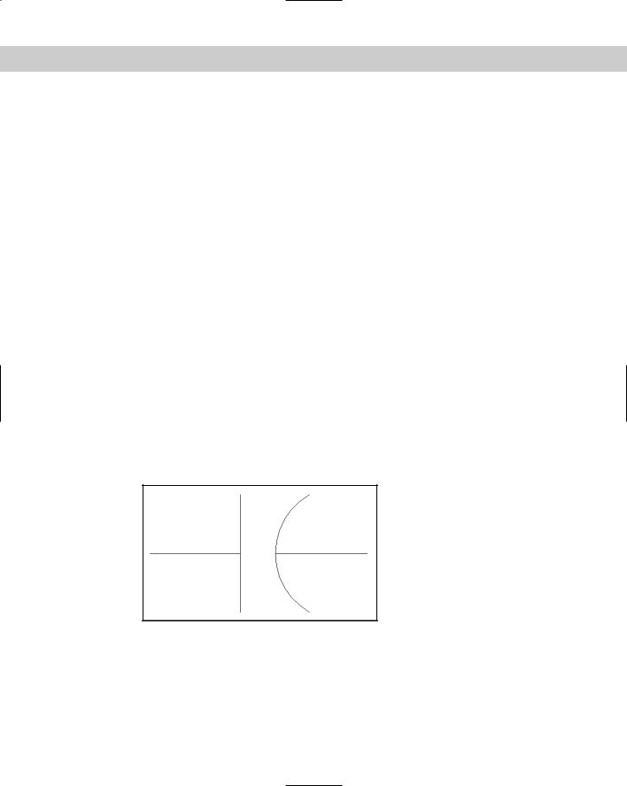
3.Choose Erase on the Modify toolbar. At the Select objects: prompt, pick the line and two arcs to the bottom-right of the two centerlines and then press Enter. The resulting model should look like Figure 10-1.
4.Choose Mirror from the Modify toolbar. At the Select objects: prompt, pick the remaining exterior line and two arcs and press Enter.
5.At the Specify first point of mirror line: prompt, pick the intersection 1 in Figure 10-1. At the Specify second point of mirror line: prompt, pick the intersection 2.
2
1
3
Figure 10-1: A partially completed mounting plate
6.The command prompts: Delete source objects? [Yes/No] <N>: Press Enter to accept the default, No.
7.Again choose Mirror from the Modify toolbar. At the Select objects: prompt, type p to pick the original lines. Then pick the new exterior line and two arcs and then press Enter.

Chapter 10 Editing Your Drawing: Advanced Tools |
183 |
8.At the Specify first point of mirror line: prompt, pick the intersection 2. At the Specify second point of mirror line: prompt, pick the intersection 3. Press Enter again at the Delete source objects? [Yes/No] <N>: prompt.
9.The command completes the mounting plate. Save your drawing. It should look like Figure 10-2.
Figure 10-2: The completed mounting plate.
Using the ARRAY command
The ARRAY command creates a rectangular or circular (polar) pattern by copying the object(s) you select as many times as you specify. The ARRAY command is a powerful drawing tool. It can quickly create large numbers of objects — saving a huge amount of time and effort.
Rectangular arrays
A rectangular array creates a grid of rows and columns of one or more objects. Figure 10-3 shows an example of a rectangular array. To create a rectangular array, follow these steps:
1.Select the object or objects and choose Array from the Modify toolbar. Alternatively, choose Array from the Modify toolbar and select the object
or objects. The Array dialog box opens, as shown in Figure 10-4.
Figure 10-3: The garage door was drawn with one panel, as shown on the left side. A rectangular array created the rest of the door panels, as shown on the right.
Thanks to Henry Dearborn, AIA, Fairfield, Iowa, for this drawing.

184 Part II Drawing in Two Dimensions
Figure 10-4: The Array dialog box.
2.Click Rectangular Array at the upper-left corner of the dialog box (if it is not already selected).
3.If you’ve already selected one or more objects, the dialog box indicates the number of selected objects. If you haven’t selected any object, click Select Objects to return to your drawing and select objects. Press Enter to end object selection and return to the dialog box.
4.Type the number of rows and columns you want in the Rows and Columns text boxes. Press Tab after the last number you type to see the new result in the preview panel.
5.Type the row offset (the distance between the rows). The preview panel doesn’t display any change when you change the row or column offsets.
6.Type the column offset (the distance between the columns).
7.If you want to specify the offsets by picking points on your screen, click one of the following buttons:
•Pick Both Offsets
• Pick Row Offset
• Pick Column Offset
8.If you want to change the angle of the array, type an angle. The preview panel displays the results of this value. To specify the angle by picking, click the Pick Angle
of Array button.
9.To preview the array, click Preview. Then choose Accept to create the array, Modify to return to the Array dialog box, or Cancel to end the command.
10.To create the array, click OK.
If you change the Snap angle or the UCS (as explained in Chapter 8), AutoCAD and AutoCAD LT create the rectangular array at the angle of the snap or UCS.
Chapter 10 Editing Your Drawing: Advanced Tools |
185 |
Tip |
If you need to create a number of copies of an object along a straight path, use a one-column |
|
or one-row array instead of the COPY command. It’s faster and easier. |
Polar (circular) arrays
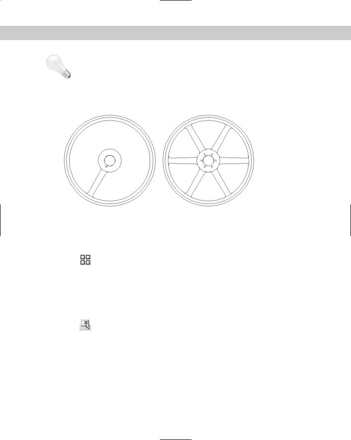
A polar array creates copies of one or more objects arrayed in a circle around a center point. An example of a polar array is shown in Figure 10-5.
Figure 10-5: The pulley was drawn with one spoke, as shown on the left. A polar array created the additional spokes.
Thanks to Robert Mack of the Dexter Company, Fairfield, Iowa, for this drawing.
To create a polar array, follow these steps:
1.Select the object or objects and choose Array from the Modify toolbar. Alternatively, choose Array from the Modify toolbar and select the object
or objects. The Array dialog box opens.
2.Click Polar Array at the top of the dialog box (if it is not already selected).
3.If you’ve already selected one or more objects, the dialog box indicates the number of selected objects. If you haven’t selected any object, click Select Objects to return to your drawing and select objects. Press Enter to end object selection and return to the dialog box.
4.Specify the center point by typing X and Y coordinates or click the Pick Center Point button. If you selected an object first, check that the center point displayed
is what you want.
5.Select the two items that you want to specify from the Method drop-down box. You can choose any two from the three choices:
•Total Number of Items: Sets the total number of items in the resulting array, including the one you’re arraying.
•Angle to Fill: Sets the number of degrees the polar array covers. For example, to array around half a circle, specify 180°.
•Angle Between Items: Specifies the number of degrees between each item in the polar array.

186 Part II Drawing in Two Dimensions
6.Complete the values of the two items you specified. You can click the buttons to pick the angle to fill or the angle between items on the screen.
7.Check the Rotate Items as Copied check box to rotate the objects that you’re arraying. Uncheck the box to leave them unrotated.
8.Click Preview to preview the array. Then choose Accept to create the array, Modify to return to the dialog box or Cancel to cancel the command.
9.Click OK to create the array.
You can specify which point on the last object selected AutoCAD and AutoCAD LT uses to array the objects. The command makes a calculation of the distance from the center point of the array to a base point on the last object selected. Otherwise, the command uses a default point based on the type of object selected. Table 10-1 lists the default base points. If you’re arraying more than one object, you may not get the result you want without specifying the base point. Even for one object, you may want to change the base point used.
To specify the base point, click the More button at the bottom of the dialog box. The dialog box opens up to display the Object Base Point section. Uncheck Set to Object’s Default and either type in coordinates or, more likely, click the Pick Base Point button and use an object snap to pick the desired point on an object. The preview box adjusts according to your choice but, because the preview only shows rectangles in the place of your object, the display may not be very helpful.
You can use the Express Tools COPYM command to enhance your copying options. Choose Express Modify Multiple Copy. You can create evenly spaced copies between two points, copy objects according to a specified measurement, and create arrays. For information on installing the Express Tools, see Appendix A.
Table 10-1: Object Base Points for Arrays
Type of Object |
Default Base Point |
|
|
Arc, circle, or ellipse |
Center point |
Polygon or rectangle |
First corner |
Line, polyline (2D or 3D), ray, spline, or donut |
Starting point |
Text (single-line or paragraph), block |
Insertion point |
Construction line (xline) |
Midpoint |
Region |
Grip point |
|
|
On the |
The drawing used in the following Step-by-Step exercise on arraying objects, ab10-a.dwg, |
CD-ROM |
is in the Drawings folder on the CD-ROM. |
STEP-BY-STEP: Arraying Objects
1. Open ab10-a.dwg from the CD-ROM.
Chapter 10 Editing Your Drawing: Advanced Tools |
187 |
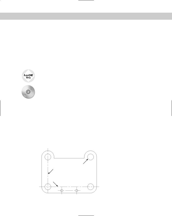
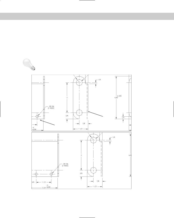
2.Save the file as ab10-02.dwg in your AutoCAD Bible folder. It looks like Figure 10-6. OSNAP should be on. Set center and intersection running object snaps.
3
 4
4
 5
5
 2
2  1
1
Figure 10-6: A partially completed mounting bracket.
3. Choose Array on the Modify toolbar. The Array dialog box opens.
4.Click the Select Objects button of the Array dialog box. In the drawing, pick the horizontal centerline 1 in Figure 10-6 and then press Enter. You return to the dialog box.
5.Make sure that Rectangular Array is selected at the top of the dialog box.
6.In the Rows text box, type 4. In the Columns text box, type 1.
7.In the Row Offset text box, type 1. (You don’t need to specify the column offset because you are only creating one column.)
8.Click Preview. You should see a total of four horizontal lines, as shown in Figure 10-7. Click Accept in the small dialog box that appears. (If you don’t see the four lines, click Modify and recheck the settings in the Array dialog box.)
9.To add the holes to the pattern, again choose Array from the Modify toolbar.
10.Click the Select Objects button in the Array dialog box. In the drawing, pick the circle 2 in Figure 10-6 and then press Enter.
11.Back in the Array dialog box, type 4 in the Rows text box and type 2 in the Columns text box.
12.Click the Pick Both Offsets button. In the drawing, pick the center of circle 2 and
the intersection of centerlines near 3 in Figure 10-6. (You can also pick the intersection of centerlines at the center of circle 2. If necessary, press Tab until you get the object snap that you want.)
13.Click Preview to preview the array. If the circles look like Figure 10-7, click Accept. Otherwise, click Modify and check your settings. After you’re done, the command arrays the holes to fit the centerlines.
14.To create a six-hole bolt circle, pick the hole 4 in Figure 10-6.
15.Choose Array from the Modify toolbar.
16.In the Array dialog box, choose Polar Array.

188 Part II Drawing in Two Dimensions
17.Next to the Center Point text boxes, click the Pick Center Point button. In the drawing, pick the center of the large circle at 5 in Figure 10-6.
18.The Method should read “Total number of items and Angle to fill.” In the Total Number of Items text box, type 6. In the Angle to Fill text box, type 360.
19.Click Preview to see the array. It should look like Figure 10-7. If it does, click Accept. Otherwise, click Modify and recheck the settings in the Array dialog box. AutoCAD or AutoCAD LT completes the mounting bracket.
20.Save your drawing. It should look like Figure 10-7.
Figure 10-7: The completed mounting bracket.
Offsetting objects
The OFFSET command creates lines or curves parallel to one existing object. The beauty of this command is apparent when you start to create complex objects, such as polylines, covered in Chapter 16. Polygons and rectangles are polylines, which means they’re treated as one object. Using OFFSET, you can create concentric polygons, for example, in one step. Figure 10-8 shows two concentric polygons. The outside polygon was created with the POLYGON command, and the inside polygon was created by using OFFSET.
Figure 10-8: Use OFFSET to create concentric polygons.
To offset an object, choose Offset from the Modify toolbar. You cannot select objects before choosing the command.
The command responds with the Specify offset distance or [Through] <1.0000>: prompt. OFFSET offers two slightly different ways to specify the offset:
Chapter 10 Editing Your Drawing: Advanced Tools |
189 |
On the
CD-ROM
If you type an offset distance, the command responds with the Select object to offset or <exit>: prompt. You can select one object. Then the Specify point on side to offset: prompt appears. Pick a point to indicate on which side of the object you want to create the offset copy. The command creates the offset and continues to show the Select object to offset or <exit>: prompt so that you can offset other objects by using the same offset distance. Press Enter to exit the command.
If you want to indicate a through point (a point that the offset passes through, such as an object snap on another object), type t or right-click and choose Through from the shortcut menu. Then the command displays the Select object to offset or <exit>: prompt. Pick one object. At the Specify through point: prompt, pick a point through which you want the offset to go to create the offset.
Use the Express Tools EXOFFSET command for expanded offset options. You can specify the layer of new objects and create multiple offsets. Choose Express Modify Extended Offset. For information on installing Express Tools, see Appendix A.
The drawing used in the following Step-by-Step exercise on using the OFFSET command, ab10-b.dwg, is in the Drawings folder on the CD-ROM.
STEP-BY-STEP: Using the OFFSET Command
1.Open ab10-b.dwg from the CD-ROM.
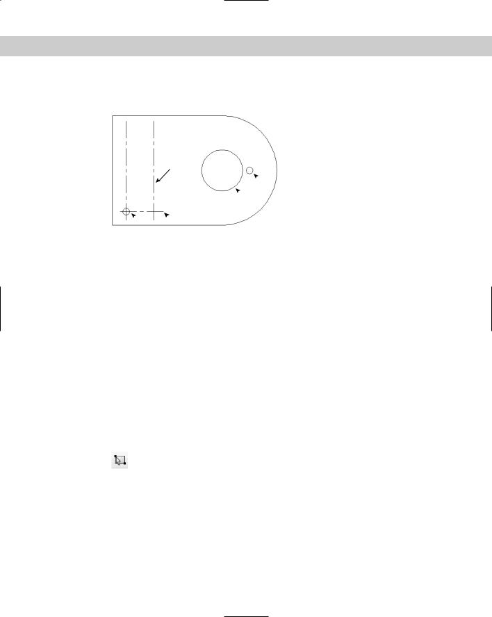
2.Save the file as ab10-03.dwg in your AutoCAD Bible folder. It looks like Figure 10-9. Set a running object snap for center and turn on OSNAP.
3.Choose Offset on the Modify toolbar. Follow the prompts:
Specify offset distance or [Through] <Through>:
Select object to offset or <exit>: Pick 1 in Figure 10-9.
Specify through point: Pick the center of 2. Select object to offset or <exit>:
This action copies the centerline through the upper circles.
2
3
4
1
Figure 10-9: A tension arm for a commercial dryer.
190 Part II Drawing in Two Dimensions
4.Choose Offset from the Modify toolbar again. At the Specify offset distance or [Through] <Through>: prompt, type 4-19/64 . Pick the centerline 3 at the Select
object to offset or <exit>: prompt, and near 4 at the Specify point on side to offset: prompt. Press Enter to end the command. The vertical centerline appears 4-19/64 units to the right of the original.
5. Save your drawing. It should look like Figure 10-10.
Figure 10-10: The completed tension arm.
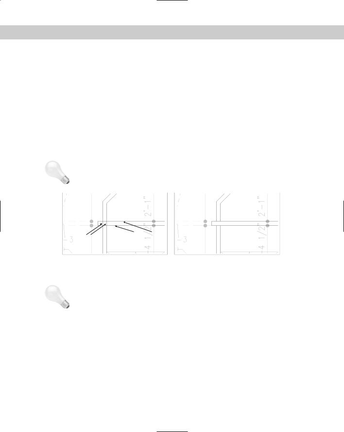
Aligning objects
The ALIGN command lets you move and rotate an object or objects in one procedure. It is especially useful in 3D work. By specifying which points on an object move where, you can align the object with other objects in your drawing, as shown in Figure 10-11. See Chapter 24 for the use of the ALIGN command in 3D editing.
1st source point
1st destination point
2nd destination point 2nd source point 
Before |
After |
Figure 10-11: Aligning a door with a wall.
Chapter 10 Editing Your Drawing: Advanced Tools |
191 |
AutoCAD LT doesn’t include the ALIGN command. Instead, you would need to use a combination of the MOVE and ROTATE commands. The Reference option of the ROTATE command would be helpful to align objects. I discuss the MOVE and ROTATE commands in Chapter 9.
Aligning requires several steps. Even so, it can save time when you need to move and rotate at the same time, especially if you don’t know the rotation angle that you need. To align an object, choose Modify 3D Operation Align and select an object or objects. Alternatively, select the object or objects first and then choose Modify 3D Operation Align. Then follow these steps:
On the
CD-ROM
1.The prompt asks for the first source point. Specify a point, usually an object snap on the object that you want to move.
2.The prompt asks for the first destination point. Specify the point where you want the first source point to end up.
3.The prompt asks for the second source point. If you press Enter, AutoCAD simply moves the selected objects. To continue to align, specify another point, usually an object snap on the object that you want to move.
4.The prompt asks for the second destination point. Specify the point where you want the second source point to end up.
5.The prompt asks for the third source point. You use this for 3D alignment, to specify how you want to rotate the object in the third dimension. For 2D alignment, press Enter to continue the command.
6.The prompt displays the Scale objects based on alignment points? [Yes/No] <N>: prompt. If the distances between the source and destination points are not the same, type y if you want to scale the original object so that the source and destination points match exactly.
The drawing used in the following Step-by-Step exercise on aligning objects in two dimensions, ab10-c.dwg, is in the Drawings folder on the CD-ROM.
STEP-BY-STEP: Aligning Objects in Two Dimensions
1.Open ab10-c.dwg from the CD-ROM.
2.Save the file as ab10-04.dwg in your AutoCAD Bible folder. It looks like Figure 10-12.
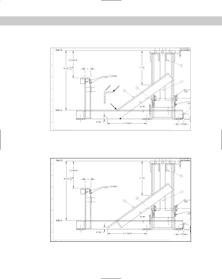
3.Choose Modify 3D Operation Align and follow the prompts:
Select objects: Select the horizontal angle by using a window, picking near 1 then 2. Press Enter to end object selection. This angle needs to be aligned with the long, diagonal support angle. Specify first source point: Pick the endpoint at 3 in Figure 10-12.
Specify first destination point: Pick the endpoint at 4 Specify second source point: Pick the endpoint at 5.
Specify second destination point: Pick the endpoint at 6 Specify third source point or <continue>:
Scale objects based on alignment points? [Yes/No] <N>:
192 Part II Drawing in Two Dimensions
This action aligns the horizontal angle with the support angle.
3 5
1 
4 2
6
Figure 10-12: A base assembly for a commercial washing machine.
Thanks to Robert Mack of the Dexter Company, Fairfield, Iowa, for this drawing.
4. Save your drawing. It should look like Figure 10-13.
Figure 10-13: The washing machine base.
Chapter 10 Editing Your Drawing: Advanced Tools |
193 |
Tip
Tip
Resizing commands
Four additional commands resize objects. The TRIM and EXTEND commands bring the endpoint of an object to another object. LENGTHEN lets you lengthen or shorten a line, polyline, arc, or elliptical arc. STRETCH is used to stretch (larger or shorter) a group of objects, letting you change their direction at the same time.
Trimming objects
As you edit a drawing, you may find that lines or arcs that once perfectly met other objects now hang over. To trim an object, you must first specify the cutting edge, which defines the point at which to cut the object you want to trim. You define the cutting edge by selecting an object. You can select several cutting edges and several objects to trim at one time, as shown in Figure 10-14. When you select an object to trim, you must pick the object on the side that you want trimmed (not on the side that you want to remain). A common use for the TRIM command is to create intersections of walls in architectural floor plans.
While using the TRIM command, you can switch to extending objects by pressing the Shift key as you select objects to trim.
Pick points |
Cutting Edges |
|
|
on lines |
|
Before trimming |
After trimming |
Figure 10-14: Trimming two objects by using two cutting edges.
Generally, you pick the objects to be trimmed individually. You cannot use Windows to select them. However, you can use the Fence object-selection method. The command trims the side of the object that the fence line crosses. You can also press Enter at the Select cutting edges: prompt. Then, when you select the objects you want to trim, AutoCAD or AutoCAD LT automatically uses the cutting edge nearest your pick point. You can use this feature to trim to multiple cutting edges without having to specify each cutting edge.
The object you want to trim does not have to actually intersect the cutting edge. You can trim an object to a cutting edge that would intersect the object if extended. This is called trimming to an implied intersection, shown in Figure 10-15.
You can trim arcs, circles, ellipses, elliptical arcs, lines, polylines, xlines, rays, and splines. You can use polylines, arcs, circles, ellipses, elliptical arcs, lines, rays, regions, splines, text, or xlines as cutting edges. An object can be used as both a cutting edge and an object to be trimmed in the same trimming process. You can also trim to objects within blocks. (Chapter 18 covers blocks.)

194 Part II Drawing in Two Dimensions
Cutting edge
Pick points on arc
Before trimming |
After trimming |
Figure 10-15: Trimming two arcs to an implied intersection.
To trim an object, choose Trim from the Modify toolbar. You cannot select objects before starting the TRIM command. The command displays the Current settings:
|
Projection=UCS, Edge=None Select cutting edges . . . Select objects: prompt. |
|
The prompt lets you know the values of the two system variables that affect trimming. The |
|
Projection setting is used only for 3D models. The Edge setting is used for implied intersections. |
|
When Edge is set to Extend, the command trims to the implied intersection of the cutting edge |
|
and the object to be trimmed. At this prompt, pick the object(s) that you want to use as a cut- |
|
ting edge. Press Enter to end object selection. |
Tip |
If the object you want to use for the cutting edge is already selected before you start the TRIM |
|
command, the command deselects it. At the Select cutting edges . . . prompt, you |
|
can type p to reselect that object. |
You can trim to an actual or an implied intersection (an intersection that would exist if objects were extended):
If you want to trim to an actual intersection, at the Select object to trim or shift-select to extend or [Project/Edge/Undo]: prompt, select objects to trim. Be sure to pick each object between the cutting edge and the end you want to trim off. Press Enter to end object selection. This action trims the object(s).
If you want to trim to an implied intersection, at the Select object to trim or shift-select to extend or [Project/Edge/Undo]: prompt, type e . The Extend
option responds with the Enter an implied edge extension mode [Extend/No extend] <No extend>: prompt. Type e . Then select the objects that you want to trim at the Select object to trim or shift-select to extend or [Project/ Edge/Undo]: prompt. Be sure to pick each object at or near the end that you want to trim. Press Enter to end object selection and trim the object(s).
Use the Undo option if the results of the trim are not what you want. You can then continue to select objects to trim.
On the |
The drawing used in the following Step-by-Step exercise on trimming objects, ab10-d.dwg, |
CD-ROM |
is in the Drawings folder on the CD-ROM. |
Chapter 10 Editing Your Drawing: Advanced Tools |
195 |
STEP-BY-STEP: Trimming Objects
1.Open ab10-d.dwg from the CD-ROM.
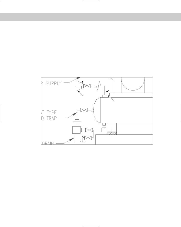
2.Save the file as ab10-05.dwg in your AutoCAD Bible folder. It looks like Figure 10-16.
3.Start the TRIM command. At the Select objects: prompt, pick lines at 1 and 2 in Figure 10-16 and then press Enter.
4.At the Select object to trim or shift-select to extend or [Project/Edge/Undo]: prompt, again pick lines at 1 and 2 in Figure 10-16. Be sure to pick them outside the intersection, as shown. Press Enter to end the command.
The command trims the lines. Each line is used as the cutting edge for the other line.
6
5
1
7
2
3
 4
4
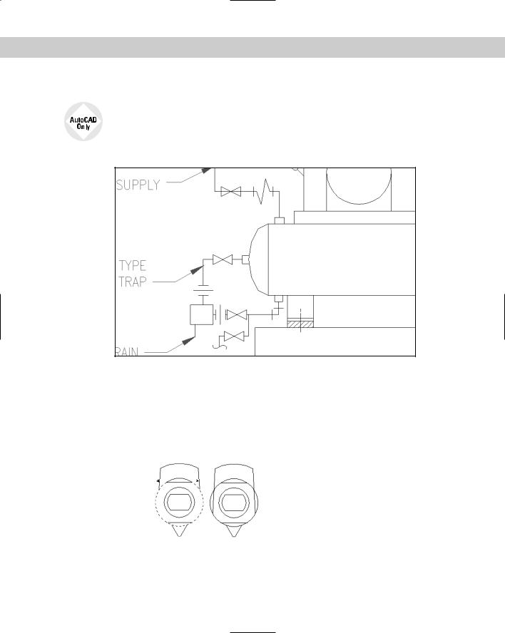
Figure 10-16: A schematic of an air compressor.
5.Choose Trim on the Modify toolbar again. At the Select objects: prompt, pick the line at 3 in Figure 10-16 and press Enter.
6.At the Select object to trim or shift-select to extend or [Project/ Edge/Undo]: prompt, right-click and choose Edge. Then right-click and choose Extend at the Enter an implied edge extension mode [Extend/No extend] <Extend>: prompt.
7.Pick the line at 4 in Figure 10-16 to trim the line. Press Enter to end the command.
8.Start the TRIM command again. At the Select objects: prompt, pick 5 and press Enter. At the Select object to trim or shift-select to extend or [Project/ Edge/Undo]: prompt, pick the lines at 6 and 7.Press Enter to end the command.
196 Part II Drawing in Two Dimensions
9. Save your drawing. It should look like Figure 10-17.
Express Tools contains a command, EXTRIM, available on the command line. EXTRIM can use a polyline, line, circle, arc, ellipse, image, or text as the cutting line. You specify one side of the cutting object, and EXTRIM trims everything on that side. For example, if you choose a closed polyline and pick inside it, every object inside the polyline is trimmed.
Figure 10-17: The completed clamp in two views.
Extending objects
The EXTEND command has the same prompts as the TRIM command, but instead of trimming objects to a cutting edge, it extends them to a boundary edge (see Figure 10-18). As with TRIM, when you select an object to extend, you must pick the object on the side that you want extended (not on the side that you want left as is).
Pick points on lines 
Boundary edge 
Figure 10-18: Extending two lines by using an arc as the boundary edge.
Chapter 10 Editing Your Drawing: Advanced Tools |
197 |
|
The object you want to extend does not have to actually intersect the boundary edge |
|
after its extension. You can extend an object to a boundary edge that would intersect |
|
the extended object if it were longer. This is called extending to an implied intersection, |
|
shown in Figure 10-19. |
|
You can extend arcs, elliptical arcs, lines, open polylines, and rays. You can use polylines, |
|
arcs, circles, ellipses, elliptical arcs, lines, rays, regions, splines, text, or xlines as boundary |
|
edges. An object can be used as both a boundary edge and an object to be extended in the |
|
same extending process. |
Tip |
While using the EXTEND command, you can switch to trimming objects by pressing the Shift |
|
key as you select objects to trim. |
Pick point on line
Boundary edge
Figure 10-19: Extending a line to an implied intersection.
198 Part II Drawing in Two Dimensions
To extend an object, choose Extend from the Modify toolbar. You cannot select objects before the EXTEND command. The command displays the Current settings:
Projection=UCS, Edge=Extend Select boundary edges ... Select objects: prompt. The prompt lets you know the values of the two settings that affect extending. Projection is used only for 3D models. Edge is used for implied intersections. When Edge is set to Extend, the command extends to the implied intersection of the boundary edge and the object to be extended. At this prompt, pick the object(s) that you want to use as the boundary edge(s). Press Enter to end object selection. You can extend to an actual or implied intersection:
If the extension will result in an actual intersection, at the Select object to extend or shift-select to trim or [Project/Edge/Undo]: prompt, select objects to extend. Be sure to pick each object at the end that you want to extend. Press Enter to end object selection and extend the object(s).
If you want to extend to an implied intersection, at the prompt, right-click and choose Edge. The option responds with the Enter an implied edge extension mode [Extend/No extend] <Extend>: prompt. Right-click and choose Extend. Then select
the objects that you want to extend at the Select object to extend or shiftselect to trim or [Project/Edge/Undo]: prompt. Be sure to pick each object at the end that you want to extend. Press Enter to end object selection. This action extends the object(s).
Use the Undo option if the results of the extension are not what you want. You can then continue to select objects to extend.
You can use the Fence object selection method to select objects to extend the side of the object that the fence line crosses.
On the |
The drawing used in the following Step-by-Step exercise on extending objects, ab10-e.dwg, |
CD-ROM |
is in the Drawings folder on the CD-ROM. |
STEP-BY-STEP: Extending Objects
1.Open ab10-e.dwg from the CD-ROM.
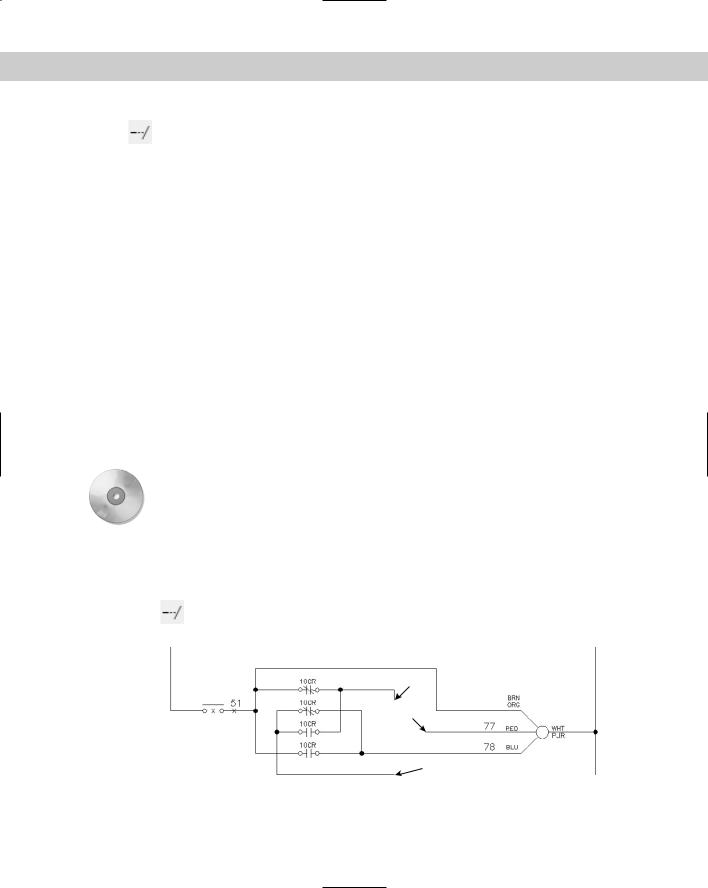
2.Save the file as ab10-06.dwg in your AutoCAD Bible folder. It looks like Figure 10-20.
3.Choose Extend on the Modify toolbar. At the Select objects: prompt, pick the line at 1 in Figure 10-20 and then press Enter.
3
4
 2 1
2 1
Figure 10-20: An electrical schematic.
Chapter 10 Editing Your Drawing: Advanced Tools |
199 |
4.At the Select object to extend or shift-select to trim or [Project/Edge/ Undo]: prompt, pick the line at 2 in Figure 10-20. Press Enter to finish selecting objects. The command extends the line.
5.Repeat the EXTEND command. At the Select objects: prompt, pick the lines at 3 and 4 in Figure 10-20 and then press Enter.
6.At the Select object to extend or shift-select to trim or [Project/Edge/ Undo]: prompt, right-click and choose Edge. Right-click and choose Extend at the
Extend/No extend <No extend>: prompt.
7.Pick lines 3 and 4 in Figure 10-20 again at the points shown. The lines extend to meet. Press Enter to end the command.
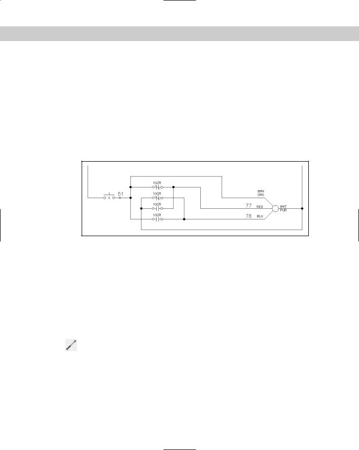
8.Save your drawing. It should look like Figure 10-21.
Figure 10-21: The completed electrical schematic.
Lengthening objects
The LENGTHEN command both lengthens and shortens. It works on open objects, such as lines, arcs, and polylines and also increases or decreases the included angle of arcs. (You can both change the length of an arc and change its included angle by using LENGTHEN.) AutoCAD and AutoCAD LT offer several ways of defining the new length or included angle. Use LENGTHEN when you want to lengthen or shorten an object, but there is no available intersecting edge or boundary to use with TRIM or EXTEND.
In the LENGTHEN command, the length of an arc is measured along its circumference. Don’t confuse this with the Length of Chord option of the ARC command, which refers to the length of a line stretched from one endpoint of the arc to the other endpoint.
To lengthen (or shorten) an object, choose Modify Lengthen. You cannot select objects before the LENGTHEN command. The command responds with the Select an object
or [DElta/Percent/Total/DYnamic]: prompt. Choose one of the following options:
Select object: This is the default. However, its purpose is to display the current measurements of the object. This can help you to decide how to define the final length or angle of the object. The current length is displayed at the command line, and the previous prompt is repeated.
200 Part II Drawing in Two Dimensions
DElta: Right-click and choose DElta. Delta means the change, or difference, between the current and new length or included angle. The option responds with the Enter delta length or [Angle] <0.0000>: prompt. If you want to change an included angle, right-click and choose Angle. Then type the change in the included angle. Otherwise, simply type in the change in the length of the object. A positive number increases the length or included angle. A negative number decreases the length or included angle.
Percent: Right-click and choose Percent. At the Enter percentage length <100.0000>: prompt, type in what percent of the original object you want the final object to be. Amounts over 100 lengthen the object. Amounts under 100 shorten the object. You cannot change an included angle using this option.
Total: Right-click and choose Total. At the Specify total length or [Angle] <1.0000)>: prompt, you can either choose the Angle suboption, as described for the Delta option or use the default total-length option. Either way, you enter the total angle or length you want.
DYnamic: Right-click and choose DYnamic. This option lets you drag the endpoint of the object closest to where you picked it. You can use an object snap to specify the new endpoint.
After you’ve used an option to specify the length you want, you see the Select an object to change or [Undo]: prompt. Here you select the object you want to change. Be sure to pick the endpoint of the object for which you want to make the change.
The same prompt continues so that you can pick other objects by using the same length specifications. Choose Undo to undo the last change. Press Enter to end the command.
On the |
The drawing used in the following Step-by-Step exercise on lengthening and shortening |
CD-ROM |
objects, ab10-f.dwg, is in the Drawings folder on the CD-ROM. |
STEP-BY-STEP: Lengthening and Shortening Objects
1.Open ab10-f.dwg from the CD-ROM.
2.Save the file as ab10-07.dwg in your AutoCAD Bible folder. It is a capacitor symbol from an electrical schematic, as shown in Figure 10-22.
2
1
Figure 10-22: A poorly drawn capacitor symbol.
Chapter 10 Editing Your Drawing: Advanced Tools |
201 |
3. Choose Modify Lengthen and follow the prompts:
Select an object or [DElta/Percent/Total/DYnamic]: Pick the line at
1 in Figure 10-22.
Current length: 0.200
Select an object or [DElta/Percent/Total/DYnamic]: Right-click and
choose Delta.
Enter delta length or [Angle] <0.000>: .07
Select an object to change or [Undo]: Pick the line at 1 in Figure
10-22.
Select an object to change or [Undo]:
This action lengthens the line.
4.Start the LENGTHEN command again and follow the prompts:
Select an object or [DElta/Percent/Total/DYnamic]: Pick the arc at 2 in Figure 10-22.
Current length: 0.407, included angle: 150
Select an object or [DElta/Percent/Total/DYnamic]: Right-click and choose Total.
Specify total length or [Angle] <1.000)>:)>: Right-click and choose Angle.
Specify total angle <57>: 120
Select an object to change or [Undo]: Pick the arc at 2 in Figure
10-22.
Select an object to change or [Undo]:
This action shortens the arc.
5.Save your drawing. It should look like Figure 10-23.
Figure 10-23: The completed capacitor symbol.
Stretching objects
The STRETCH command is generally used to stretch groups of objects. It can be used to enlarge a room in a floor plan, for example. You can also shrink objects. You can change not only the length of the objects but the angle as well. You use a crossing window to choose the objects
202 Part II Drawing in Two Dimensions
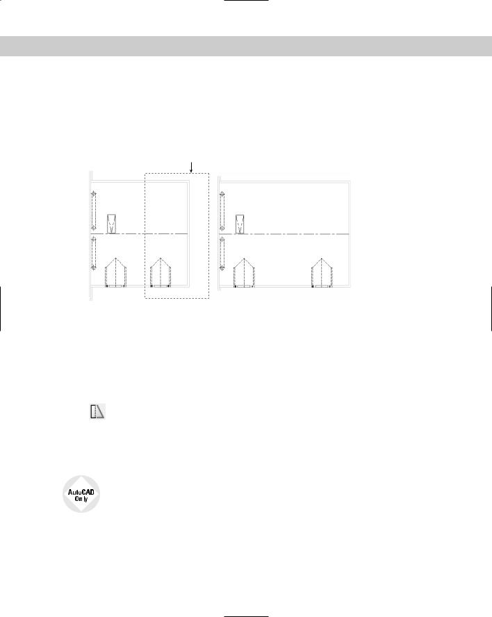
to be stretched. All objects that cross the boundaries of the crossing window are stretched. All objects that lie entirely within the crossing window are merely moved. Successful stretching involves precise placement of the crossing window. Figure 10-24 shows the process of stretching a garage. Note that the walls that cross the boundaries of the crossing window are stretched. However, the dormer that is entirely within the crossing window is just moved. This maintains the integrity of the model.
Crossing window
Before stretching |
After stretching |
Figure 10-24: Stretching a garage.
You cannot stretch circles, text, or blocks. You can stretch arcs, although the results may not be what you expect.
The real power of the STRETCH command is in stretching a number of objects at once. However, you can also stretch one line. The results are similar to using the CHANGE command to change the endpoint of a line.
To stretch objects, choose Stretch from the Modify toolbar. The command responds with the Select objects to stretch by crossing-window or crossing-
polygon . . . instruction and then the Select objects: prompt. Create the crossing window and select the objects that you want to stretch. (You can also use a crossing polygon.) After completing the crossing window, check to see which objects are highlighted. This helps you avoid unwanted results. You can use the object selection Remove option (type r at the command prompt) to remove objects by picking the objects you don’t want to stretch or move.
To allow you to use multiple crossing windows or polygons to select the objects that you want to stretch, use the Express Tools MSTRETCH command. Choose Express Modify Multiple Entity Stretch. For information on installing Express Tools, see Appendix A.
You then see the Specify base point or displacement: prompt. This step is just like moving objects. You can respond in two ways.
Pick a base point. At the Specify second point of displacement or <use first point as displacement>: prompt, pick a second point. Object snap and PolarSnap are helpful for picking these points.
Chapter 10 Editing Your Drawing: Advanced Tools |
203 |
|
Type a displacement, without using the @ sign. For example, to lengthen the objects by |
|
6 feet in the 0-degree direction, type 6'<0 . Then press Enter at the Specify second |
|
point of displacement or <use first point as displacement>: prompt. |
Tip |
Usually, you want to stretch at an orthogonal angle. If you’re going to stretch by picking, turn |
|
ORTHO on. Object snaps, polar tracking, and snap mode are other helpful drawing aids for |
|
stretching. |
|
When specifying a displacement by typing at the keyboard, you can use both positive and |
|
negative distances. For example, 6'<180 is the same as –6'<0. Both would stretch the objects |
|
6 feet to the left. |
|
In this exercise, you practice stretching objects. |
On the |
The drawing used in the following Step-by-Step exercise, ab10-g.dwg, is in the Drawings |
CD-ROM |
folder on the CD-ROM. |
|
STEP-BY-STEP: Stretching Objects
1.Open ab10-g.dwg from your CD-ROM.
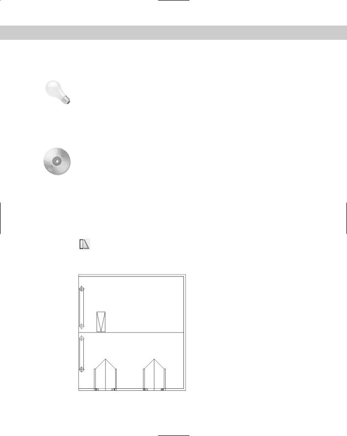
2.Save the file as ab10-08.dwg in your AutoCAD Bible folder. This drawing is the plan view of a garage, as shown in Figure 10-25. Turn on polar tracking by clicking POLAR on the status bar. Click SNAP on the status bar and then right-click SNAP to make sure PolarSnap is on (the PolarSnap item will be unavailable if it is already on); otherwise, choose PolarSnap. Turn on OSNAP and set a running object snap for endpoints.
3.Choose Stretch from the Modify toolbar. At the Select objects: prompt, pick 1 in Figure 10-25. At the Specify opposite corner: prompt, pick 2. The prompt
notifies you that it found 32 objects. Press Enter to end object selection.
1
2
Figure 10-25: A plan view of a garage.