

- •Foreword
- •Preface
- •Is This Book for You?
- •How This Book Is Organized
- •How to Use This Book
- •Doing the Exercises
- •Conventions Used in This Book
- •What the Icons Mean
- •About the CD-ROM
- •Other Information
- •Contacting the Author
- •Acknowledgments
- •Contents at a Glance
- •Contents
- •Getting Acquainted with AutoCAD and AutoCAD LT
- •Starting AutoCAD and AutoCAD LT
- •Creating a New Drawing
- •Using the AutoCAD and AutoCAD LT Interface
- •Creating Your First Drawing
- •Saving a Drawing
- •Summary
- •Creating a New Drawing from a Template
- •Working with Templates
- •Opening a Drawing with Default Settings
- •Opening an Existing Drawing
- •Using an Existing Drawing as a Prototype
- •Saving a Drawing Under a New Name
- •Summary
- •The Command Line
- •Command Techniques
- •Of Mice and Pucks
- •Getting Help
- •Summary
- •Typing Coordinates
- •Displaying Coordinates
- •Picking Coordinates on the Screen
- •Locating Points
- •Summary
- •Unit Types
- •Drawing Limits
- •Understanding Scales
- •Inserting a Title Block
- •Common Setup Options
- •The MVSETUP Command
- •Summary
- •Using the LINE Command
- •Drawing Rectangles
- •Drawing Polygons
- •Creating Construction Lines
- •Creating Rays
- •Summary
- •Drawing Circles
- •Drawing Arcs
- •Creating Ellipses and Elliptical Arcs
- •Making Donuts
- •Placing Points
- •Summary
- •Panning
- •The ZOOM Command
- •Aerial View
- •Named Views
- •Tiled Viewports
- •Snap Rotation
- •User Coordinate Systems
- •Isometric Drawing
- •Summary
- •Editing a Drawing
- •Selecting Objects
- •Summary
- •Copying and Moving Objects
- •Using Construction Commands
- •Creating a Revision Cloud
- •Hiding Objects with a Wipeout
- •Double-Clicking to Edit Objects
- •Grips
- •Editing with the Properties Palette
- •Selection Filters
- •Groups
- •Summary
- •Working with Layers
- •Changing Object Color, Linetype, and Lineweight
- •Working with Linetype Scales
- •Importing Layers and Linetypes from Other Drawings
- •Matching Properties
- •Summary
- •Drawing-Level Information
- •Object-Level Information
- •Measurement Commands
- •AutoCAD’s Calculator
- •Summary
- •Creating Single-Line Text
- •Understanding Text Styles
- •Creating Multiline Text
- •Creating Tables
- •Inserting Fields
- •Managing Text
- •Finding Text in Your Drawing
- •Checking Your Spelling
- •Summary
- •Working with Dimensions
- •Drawing Linear Dimensions
- •Drawing Aligned Dimensions
- •Creating Baseline and Continued Dimensions
- •Dimensioning Arcs and Circles
- •Dimensioning Angles
- •Creating Ordinate Dimensions
- •Drawing Leaders
- •Using Quick Dimension
- •Editing Dimensions
- •Summary
- •Understanding Dimension Styles
- •Defining a New Dimension Style
- •Changing Dimension Styles
- •Creating Geometric Tolerances
- •Summary
- •Creating and Editing Polylines
- •Drawing and Editing Splines
- •Creating Regions
- •Creating Boundaries
- •Creating Hatches
- •Creating and Editing Multilines
- •Creating Dlines
- •Using the SKETCH Command
- •Digitizing Drawings with the TABLET Command
- •Summary
- •Preparing a Drawing for Plotting or Printing
- •Creating a Layout in Paper Space
- •Working with Plot Styles
- •Plotting a Drawing
- •Summary
- •Combining Objects into Blocks
- •Inserting Blocks and Files into Drawings
- •Managing Blocks
- •Using Windows Features
- •Working with Attributes
- •Summary
- •Understanding External References
- •Editing an Xref within Your Drawing
- •Controlling Xref Display
- •Managing Xrefs
- •Summary
- •Preparing for Database Connectivity
- •Connecting to Your Database
- •Linking Data to Drawing Objects
- •Creating Labels
- •Querying with the Query Editor
- •Working with Query Files
- •Summary
- •Working with 3D Coordinates
- •Using Elevation and Thickness
- •Working with the User Coordinate System
- •Summary
- •Working with the Standard Viewpoints
- •Using DDVPOINT
- •Working with the Tripod and Compass
- •Getting a Quick Plan View
- •Shading Your Drawing
- •Using 3D Orbit
- •Using Tiled Viewports
- •Defining a Perspective View
- •Laying Out 3D Drawings
- •Summary
- •Drawing Surfaces with 3DFACE
- •Drawing Surfaces with PFACE
- •Creating Polygon Meshes with 3DMESH
- •Drawing Standard 3D Shapes
- •Drawing a Revolved Surface
- •Drawing an Extruded Surface
- •Drawing Ruled Surfaces
- •Drawing Edge Surfaces
- •Summary
- •Drawing Standard Shapes
- •Creating Extruded Solids
- •Drawing Revolved Solids
- •Creating Complex Solids
- •Sectioning and Slicing Solids
- •Using Editing Commands in 3D
- •Editing Solids
- •Listing Solid Properties
- •Summary
- •Understanding Rendering
- •Creating Lights
- •Creating Scenes
- •Working with Materials
- •Using Backgrounds
- •Doing the Final Render
- •Summary
- •Accessing Drawing Components with the DesignCenter
- •Accessing Drawing Content with Tool Palettes
- •Setting Standards for Drawings
- •Organizing Your Drawings
- •Working with Sheet Sets
- •Maintaining Security
- •Keeping Track of Referenced Files
- •Handling Errors and Crashes
- •Managing Drawings from Prior Releases
- •Summary
- •Importing and Exporting Other File Formats
- •Working with Raster Images
- •Pasting, Linking, and Embedding Objects
- •Summary
- •Sending Drawings
- •Opening Drawings from the Web
- •Creating Object Hyperlinks
- •Publishing Drawings
- •Summary
- •Working with Customizable Files
- •Creating Keyboard Shortcuts for Commands
- •Customizing Toolbars
- •Customizing Tool Palettes
- •Summary
- •Creating Macros with Script Files
- •Creating Slide Shows
- •Creating Slide Libraries
- •Summary
- •Creating Linetypes
- •Creating Hatch Patterns
- •Summary
- •Creating Shapes
- •Creating Fonts
- •Summary
- •Working with Menu Files
- •Customizing a Menu
- •Summary
- •Introducing Visual LISP
- •Getting Help in Visual LISP
- •Working with AutoLISP Expressions
- •Using AutoLISP on the Command Line
- •Creating AutoLISP Files
- •Summary
- •Creating Variables
- •Working with AutoCAD Commands
- •Working with Lists
- •Setting Conditions
- •Managing Drawing Objects
- •Getting Input from the User
- •Putting on the Finishing Touches
- •Summary
- •Understanding Local and Global Variables
- •Working with Visual LISP ActiveX Functions
- •Debugging Code
- •Summary
- •Starting to Work with VBA
- •Writing VBA Code
- •Getting User Input
- •Creating Dialog Boxes
- •Modifying Objects
- •Debugging and Trapping Errors
- •Moving to Advanced Programming
- •A Final Word
- •Installing AutoCAD and AutoCAD LT
- •Configuring AutoCAD
- •Starting AutoCAD Your Way
- •Configuring a Plotter
- •System Requirements
- •Using the CD with Microsoft Windows
- •What’s on the CD
- •Troubleshooting
- •Index
410 Part II Drawing in Two Dimensions
Summary
In this chapter, you gained a thorough understanding of how to use dimension styles to organize your dimensions. You read how to:
Define a dimension’s lines and arrows
Define dimension text style and placement
Fit dimensions into small spaces
Define the primary and alternate measuring units
Format tolerances
Create a variant of a dimension style for specific types of dimensions
Change dimension style used by a dimension
Modify a dimension style and update all dimensions that use that style
Override a dimension style for temporary changes
Update existing dimensions
Compare dimension styles
Copy dimension styles from other drawings using the DesignCenter
Create geometric tolerances
In the next chapter, you learn how to draw complex objects.
|
|
|
Drawing Complex
Objects
AutoCAD and AutoCAD LT offer a number of complex objects that can help you create accurate, professional drawings. Polylines
are single objects that can combine line segments and arcs. Splines are mathematically controlled curves based on points you specify. Regions and boundaries create complex shapes from existing objects. Hatches create various types of fills. Multilines (in AutoCAD) and dlines (in AutoCAD LT) are sets of parallel lines. Sketching is a way to create freehand drawings. Digitizing with a tablet is a process that is used to transfer an existing paper drawing into your drawing. In this chapter, I introduce you to these complex objects and explain how to use them.
Creating and Editing Polylines
Polylines are single objects that combine line segments and arcs. In certain situations, being able to edit an entire set of lines and arcs as one object is useful. Polylines can have a width, which can vary from the start point to the endpoint of each segment. Polylines ensure that all the vertices of a series of lines and arcs actually touch. They’re also useful for 3D drawing. In short, polylines are a neat, clean way to draw. (Technically, polylines are called lightweight polylines to distinguish them from the type of polylines used in Release 13 and earlier.)
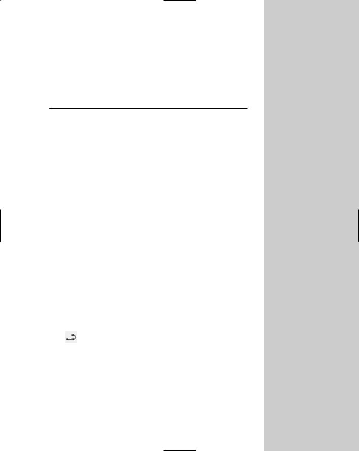
The RECTANG and POLYGON commands create polylines. Figure 16-1 shows a few examples of polylines.
Using the PLINE command
To draw a polyline, choose Polyline from the Draw toolbar. This starts the PLINE command. The command responds with the
Specify start point: prompt. Specify the start point. Then you see the Specify next point or [Arc/Close/Halfwidth/Length/ Undo/Width]: prompt. It offers the following options:
Arc: Draws arcs. This option opens up a set of arc suboptions, which are explained next, after this list.
Close: Closes a polyline by drawing a line from the endpoint of the last line segment to the start point of the polyline. This option appears only after you’ve picked a second point.
16C H A P T E R
In This Chapter
Creating and editing polylines
Drawing and editing splines
Creating regions and boundaries
Using hatches to fill closed areas
Creating and editing multilines and dlines
Using the SKETCH command
Digitizing drawings with the TABLET command
412 Part II Drawing in Two Dimensions
Halfwidth: Defines half the width of the polyline — the distance from the center of the polyline to its edge. The option asks you for the starting halfwidth and the ending halfwidth, enabling you to create polylines that are tapered.
Length: Specifies the length of the next line segment. The option draws the line segment in the same direction as the last line segment or tangent to the last arc.
Undo: Undoes the last line segment.
Width: Defines the width of the polyline. The option asks you for the starting width and the ending width.
Specify next point: Enables you to create a line segment. This is the default option.
Figure 16-1: Some polylines.
Like the LINE command, PLINE continues to prompt you for more points, repeating the entire prompt each time. When you’re done, press Enter to end the command.
If you choose Arc, you see the Specify endpoint of arc or [Angle/CEnter/CLose/ Direction/Halfwidth/Line/Radius/Second pt/ Undo/Width]: prompt. Although this may seem overwhelming, most of the options are similar to the ARC command options. If you need a review, see Chapter 7. The arc options are as follows:
Angle: Specifies the included angle.
CEnter: Specifies the arc’s center.
CLose: Closes the polyline by drawing an arc from the endpoint of the last arc to the start point of the polyline.
Direction: Specifies the direction of the arc from the start point.
Halfwidth: Defines half the width of the polyline — the distance from the center of the polyline to its edge. The option asks you for the starting halfwidth and the ending halfwidth.
Line: Returns you to the main polyline prompt so you can draw line segments.
Radius: Specifies the arc’s radius.
Second pt: Specifies the second point of the arc.
Undo: Undoes the last arc.

Chapter 16 Drawing Complex Objects 413
Width: Defines the width of the polyline. The option asks you for the starting width and the ending width.
Specify endpoint of arc: Specifies the endpoint of the arc. This is the default. This option creates an arc tangent to the previous arc (continuing in the same direction).
PLINE continues to display the arc submenu until you use the Line suboption or end the command by pressing Enter.
On the |
The drawing used in the following Step-by-Step exercise on drawing polylines, ab16-a.dwg, |
CD-ROM |
is in the Drawings folder on the CD-ROM. |
STEP-BY-STEP: Drawing Polylines
1.Open ab16-a.dwg from your CD-ROM.
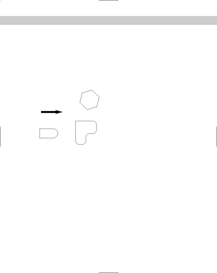
2.Save the file as ab16-01.dwg in your AutoCAD Bible folder. It shows a small section of a drive block, as shown in Figure 16-2. In this exercise, you complete part of the drawing. ORTHO and OSNAP should be on. Set running object snaps to endpoint, midpoint, and intersection. Layer 3 should be current.
3. Choose Polyline from the Draw toolbar. Follow the prompts:
Specify start point: Press Shift+right-click and choose the From object snap.
Base point: Choose 1 in Figure 16-2. <Offset>: @–1/2,0
Specify next point or [Arc/ Halfwidth/Length/Undo/Width]: Move the cursor in the 90-degree direction and type 3/32 .
4.Type a to continue with an arc. At the Specify endpoint of arc or [Angle/
CEnter/CLose/Direction/Halfwidth/Line/Radius/Second pt/Undo/Width]: prompt, type @3/16,3/16 .
2 1
Figure 16-2: A small section of a drive block.
Thanks to Mary Redfern of the Bethlehem Corporation, Easton, Pennsylvania, for this drawing.
414 Part II Drawing in Two Dimensions
On the
CD-ROM
5.Type l to continue with a linear segment. At the Specify next point or [Arc/
Close/Halfwidth/Length/Undo/Width]: prompt, move the cursor in the 0-degree direction and type 11/32 .
6.Type a to continue with an arc. At the prompt, type @3/16,3/16 .
7.Type l to continue with a linear segment. At the prompt, move the cursor in the 90-degree direction and type 6-3/32 .
8.Type a to continue with an arc. At the prompt, type @-5/16,5/16 .
9.To create the last arc, type r . Follow the prompts:
Specify radius of arc: 5-5/8
Specify endpoint of arc or [Angle]: Choose the From object snap.
Base point: Choose point 2 in Figure 16-2. <Offset>: @0,7-1/4
10.Press Enter to exit the PLINE command.
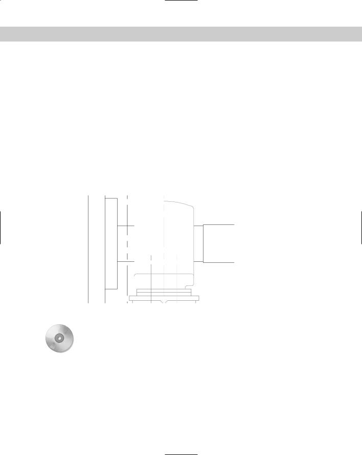
11.Save your drawing. It should look like Figure 16-3.
Figure 16-3: The completed polyline.
Ar1 creates a label of the area of an enclosed polyline. Look in \Software\Ch16\ar1. Note that you can also create a similar label using the area field (AutoCAD only). I cover fields in Chapter 13.
Editing polylines with the PEDIT command
Because polylines can be quite complex, there is a special command to edit them, PEDIT. To edit a polyline, choose Modify Object Polyline. The command responds with the Select polyline or [Multiple]: prompt. Select a polyline and you see the Enter an option [Close/Join/Width/Edit vertex/Fit/Spline/Decurve/Ltype gen/Undo]: prompt. The options are:

Chapter 16 Drawing Complex Objects 415
Close: Closes an open polyline. If necessary, it adds a segment to connect the endpoint to the start point. If the polyline is already closed, this prompt becomes Open. Open creates a break between the first and last segments of the polyline.
Join: Joins touching lines, arcs, or other polylines to the polyline.
Width: Enables you to specify one width for the entire polyline.
Edit Vertex: Provides a set of suboptions for editing vertices. These suboptions are explained after this list.
Fit: Turns the polyline into a curve that passes through the vertices.
Spline: Creates a curve by using the vertices as control points. The curve does not usually pass through the vertices. This is not the mathematically exact spline that the SPLINE command produces (covered later in this chapter).
Decurve: Returns a Fit or Spline curve to its original vertices.
Ltype gen: Turns on continuous linetype generation for the selected polyline.
Undo: Undoes the most recent edit.
Tip |
You can change any line or arc into a polyline. Start PEDIT and choose a line or arc. The com- |
|
mand responds: Object selected is not a polyline. Do you want to turn it |
|
into one? <Y>. Press Enter to accept the default and turn the object into a polyline. (You |
|
can change the PEDITACCEPT system variable to 1 to suppress this prompt and automatically |
|
turn non-polyline objects that you select for the PEDIT command to polylines.) To turn a series |
|
of connected lines and arcs into a polyline, first, turn one of the objects into a polyline as I just |
|
explained. Then use the Join option and select the other objects individually or by a selection |
|
window. In order to create a polyline in this way, the individual lines and arcs must connect |
|
exactly end to end. However, if you use the Multiple option, explained following the current |
|
list, you can join lines that aren’t exactly touching. |
|
When you choose the Edit Vertex option, you see a new set of suboptions, with the Enter a |
|
vertex editing option [Next/Previous/Break/Insert/ Move/Regen/Straighten/ |
|
Tangent/Width/eXit] <N>: prompt. You see an X at one of the vertices. This is the current |
|
vertex, which you can edit. The suboptions are as follows: |
Next: Moves you to the next vertex so you can edit it.
Previous: Moves you to the previous vertex.
Break: Breaks the polyline. You can choose the Go suboption to break the polyline into two (although you can’t see the break). You can move to another vertex using the Next or Previous suboptions and then choose Go. This option breaks the polyline between the original vertex and the vertex you moved to. Use the eXit suboption to return to the previous prompt. (You can also use the BREAK command.)
Insert: Inserts another vertex. At the prompt, specify its location.
Move: Moves the vertex. At the prompt, specify its location.
Regen: Regenerates the polyline.

416 Part II Drawing in Two Dimensions
Straighten: Deletes vertices. This works like the Break option with the same Next, Previous, Go, and eXit suboptions. As soon as you move to a new vertex, the option draws a straight line between it and the original vertex. If you don’t move to a new vertex, this option affects only an arc by changing it to a straight line segment.
Tangent: Specifies a direction from the vertex. The command uses this information if you choose the Fit option.
Width: Enables you to specify a starting and ending width of the segment starting with the current vertex.
eXit: Exits this group of suboptions.
Caution |
You can make many changes during the PEDIT session. If you return to the command line and |
|
use the U or UNDO command, the entire session is undone. If you want to undo only part of |
|
the session, use the Undo options of the PEDIT command. |
You can edit polylines with grips as well. A polyline has a grip at each vertex, making it easy to move vertices.
To edit multiple polylines at one time, follow these steps:
1.Start the PEDIT command
2.Choose the Multiple option (type m or right-click and choose Multiple from the shortcut menu) at the first prompt.
3.At the Select objects: prompt, select the polylines.
4.You see the Enter an option [Close/Open/Join/Width/Fit/Spline/Decurve/ Ltype gen/Undo]: prompt.
5.Choose the option you want. For example, you can change the width of all the selected polylines or apply the Spline option to them.
You can also join two polylines that aren’t touching — if you use the Multiple option first. Select the polylines and then choose the Join option. You then need to specify two suboptions:
Fuzz distance: The maximum distance that the endpoints of the polylines can be from each other. In other words, in order for the join to work, the fuzz distance must be greater than the distance of the endpoints. If you want to join the endpoints no matter what, type in a very large number.
Jointype: The method of joining polylines. You can use the Extend method, which extends (or trims) the segments to the nearest endpoints, or the Add method, which adds a straight segment between the two nearest endpoints. You can choose the Both suboption, which tries to extend or trim, but, if it can’t, it adds a segment.
Editing polylines using the Properties palette
You can also edit polylines in the Properties palette. Double-click a polyline, and the Properties palette opens.
You can choose a vertex by clicking Vertex in the Geometry section of the dialog box. An X appears on the polyline to let you know which vertex you’ve chosen. You can then edit the vertex’s coordinates by typing them in, or by clicking the Pick a Point button that appears and picking a point in the drawing. You can change the start and ending width and specify a global width for the entire polyline.
Chapter 16 Drawing Complex Objects 417
Generating linetypes on polylines
When you create a polyline with a noncontinuous linetype, you may find that the linetype doesn’t appear properly along the polyline. One reason is that the segments of the polyline may be too short to fit the entire linetype definition — in this case the polyline appears continuous even though it’s defined with a dashed line or other linetype. You can choose to generate the linetype continuously along the polyline instead of starting the linetype definition anew at each vertex. This results in a more normal looking linetype along the polyline. To do this, you need to turn on the PLINEGEN system variable. By default it is off (set at 0). To turn on PLINEGEN, type plinegen and then 1 .
As explained in the section “Editing polylines with the PEDIT command” later in the chapter, you can also modify the display of linetypes for existing polylines.
You can close and open a polyline in the Misc section. You can also turn on continuous linetype generation for the selected polyline by choosing Linetype generation and choosing Enabled from the drop-down list that appears. Of course, you can change the layer, color, linetype, lineweight, and linetype scale as well.
You can “paint” polyline properties from one polyline to another, using the MATCHPROP command. Select a polyline, choose Match Properties on the Standard toolbar, and then select the polyline you want to edit.
On the |
The drawing used in the following Step-by-Step exercise on editing polylines, ab16-b.dwg, |
CD-ROM |
is in the Drawings folder on the CD-ROM. |
STEP-BY-STEP: Editing Polylines
1.Open ab16-b.dwg from your CD-ROM.
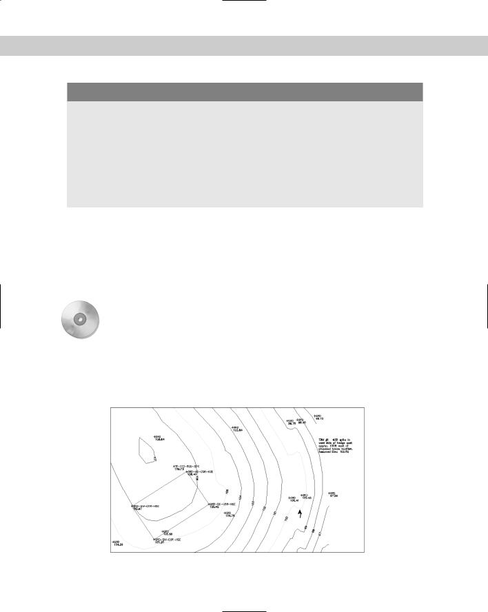
2.Save the file as ab16-02.dwg in your AutoCAD Bible folder. This is a topographical drawing, as shown in Figure 16-4. The contours are polylines.
1
Figure 16-4: The topographical drawing’s contours are polylines.
Thanks to Henry Dearborn, AIA, of Fairfield, Iowa, for this drawing.