

- •Foreword
- •Preface
- •Is This Book for You?
- •How This Book Is Organized
- •How to Use This Book
- •Doing the Exercises
- •Conventions Used in This Book
- •What the Icons Mean
- •About the CD-ROM
- •Other Information
- •Contacting the Author
- •Acknowledgments
- •Contents at a Glance
- •Contents
- •Getting Acquainted with AutoCAD and AutoCAD LT
- •Starting AutoCAD and AutoCAD LT
- •Creating a New Drawing
- •Using the AutoCAD and AutoCAD LT Interface
- •Creating Your First Drawing
- •Saving a Drawing
- •Summary
- •Creating a New Drawing from a Template
- •Working with Templates
- •Opening a Drawing with Default Settings
- •Opening an Existing Drawing
- •Using an Existing Drawing as a Prototype
- •Saving a Drawing Under a New Name
- •Summary
- •The Command Line
- •Command Techniques
- •Of Mice and Pucks
- •Getting Help
- •Summary
- •Typing Coordinates
- •Displaying Coordinates
- •Picking Coordinates on the Screen
- •Locating Points
- •Summary
- •Unit Types
- •Drawing Limits
- •Understanding Scales
- •Inserting a Title Block
- •Common Setup Options
- •The MVSETUP Command
- •Summary
- •Using the LINE Command
- •Drawing Rectangles
- •Drawing Polygons
- •Creating Construction Lines
- •Creating Rays
- •Summary
- •Drawing Circles
- •Drawing Arcs
- •Creating Ellipses and Elliptical Arcs
- •Making Donuts
- •Placing Points
- •Summary
- •Panning
- •The ZOOM Command
- •Aerial View
- •Named Views
- •Tiled Viewports
- •Snap Rotation
- •User Coordinate Systems
- •Isometric Drawing
- •Summary
- •Editing a Drawing
- •Selecting Objects
- •Summary
- •Copying and Moving Objects
- •Using Construction Commands
- •Creating a Revision Cloud
- •Hiding Objects with a Wipeout
- •Double-Clicking to Edit Objects
- •Grips
- •Editing with the Properties Palette
- •Selection Filters
- •Groups
- •Summary
- •Working with Layers
- •Changing Object Color, Linetype, and Lineweight
- •Working with Linetype Scales
- •Importing Layers and Linetypes from Other Drawings
- •Matching Properties
- •Summary
- •Drawing-Level Information
- •Object-Level Information
- •Measurement Commands
- •AutoCAD’s Calculator
- •Summary
- •Creating Single-Line Text
- •Understanding Text Styles
- •Creating Multiline Text
- •Creating Tables
- •Inserting Fields
- •Managing Text
- •Finding Text in Your Drawing
- •Checking Your Spelling
- •Summary
- •Working with Dimensions
- •Drawing Linear Dimensions
- •Drawing Aligned Dimensions
- •Creating Baseline and Continued Dimensions
- •Dimensioning Arcs and Circles
- •Dimensioning Angles
- •Creating Ordinate Dimensions
- •Drawing Leaders
- •Using Quick Dimension
- •Editing Dimensions
- •Summary
- •Understanding Dimension Styles
- •Defining a New Dimension Style
- •Changing Dimension Styles
- •Creating Geometric Tolerances
- •Summary
- •Creating and Editing Polylines
- •Drawing and Editing Splines
- •Creating Regions
- •Creating Boundaries
- •Creating Hatches
- •Creating and Editing Multilines
- •Creating Dlines
- •Using the SKETCH Command
- •Digitizing Drawings with the TABLET Command
- •Summary
- •Preparing a Drawing for Plotting or Printing
- •Creating a Layout in Paper Space
- •Working with Plot Styles
- •Plotting a Drawing
- •Summary
- •Combining Objects into Blocks
- •Inserting Blocks and Files into Drawings
- •Managing Blocks
- •Using Windows Features
- •Working with Attributes
- •Summary
- •Understanding External References
- •Editing an Xref within Your Drawing
- •Controlling Xref Display
- •Managing Xrefs
- •Summary
- •Preparing for Database Connectivity
- •Connecting to Your Database
- •Linking Data to Drawing Objects
- •Creating Labels
- •Querying with the Query Editor
- •Working with Query Files
- •Summary
- •Working with 3D Coordinates
- •Using Elevation and Thickness
- •Working with the User Coordinate System
- •Summary
- •Working with the Standard Viewpoints
- •Using DDVPOINT
- •Working with the Tripod and Compass
- •Getting a Quick Plan View
- •Shading Your Drawing
- •Using 3D Orbit
- •Using Tiled Viewports
- •Defining a Perspective View
- •Laying Out 3D Drawings
- •Summary
- •Drawing Surfaces with 3DFACE
- •Drawing Surfaces with PFACE
- •Creating Polygon Meshes with 3DMESH
- •Drawing Standard 3D Shapes
- •Drawing a Revolved Surface
- •Drawing an Extruded Surface
- •Drawing Ruled Surfaces
- •Drawing Edge Surfaces
- •Summary
- •Drawing Standard Shapes
- •Creating Extruded Solids
- •Drawing Revolved Solids
- •Creating Complex Solids
- •Sectioning and Slicing Solids
- •Using Editing Commands in 3D
- •Editing Solids
- •Listing Solid Properties
- •Summary
- •Understanding Rendering
- •Creating Lights
- •Creating Scenes
- •Working with Materials
- •Using Backgrounds
- •Doing the Final Render
- •Summary
- •Accessing Drawing Components with the DesignCenter
- •Accessing Drawing Content with Tool Palettes
- •Setting Standards for Drawings
- •Organizing Your Drawings
- •Working with Sheet Sets
- •Maintaining Security
- •Keeping Track of Referenced Files
- •Handling Errors and Crashes
- •Managing Drawings from Prior Releases
- •Summary
- •Importing and Exporting Other File Formats
- •Working with Raster Images
- •Pasting, Linking, and Embedding Objects
- •Summary
- •Sending Drawings
- •Opening Drawings from the Web
- •Creating Object Hyperlinks
- •Publishing Drawings
- •Summary
- •Working with Customizable Files
- •Creating Keyboard Shortcuts for Commands
- •Customizing Toolbars
- •Customizing Tool Palettes
- •Summary
- •Creating Macros with Script Files
- •Creating Slide Shows
- •Creating Slide Libraries
- •Summary
- •Creating Linetypes
- •Creating Hatch Patterns
- •Summary
- •Creating Shapes
- •Creating Fonts
- •Summary
- •Working with Menu Files
- •Customizing a Menu
- •Summary
- •Introducing Visual LISP
- •Getting Help in Visual LISP
- •Working with AutoLISP Expressions
- •Using AutoLISP on the Command Line
- •Creating AutoLISP Files
- •Summary
- •Creating Variables
- •Working with AutoCAD Commands
- •Working with Lists
- •Setting Conditions
- •Managing Drawing Objects
- •Getting Input from the User
- •Putting on the Finishing Touches
- •Summary
- •Understanding Local and Global Variables
- •Working with Visual LISP ActiveX Functions
- •Debugging Code
- •Summary
- •Starting to Work with VBA
- •Writing VBA Code
- •Getting User Input
- •Creating Dialog Boxes
- •Modifying Objects
- •Debugging and Trapping Errors
- •Moving to Advanced Programming
- •A Final Word
- •Installing AutoCAD and AutoCAD LT
- •Configuring AutoCAD
- •Starting AutoCAD Your Way
- •Configuring a Plotter
- •System Requirements
- •Using the CD with Microsoft Windows
- •What’s on the CD
- •Troubleshooting
- •Index
926 Part VI Customizing AutoCAD
5.Choose File Save and save it in your AutoCAD Bible folder as ab31-02.lin..
6.Choose Layer Properties Manager from the Layers toolbar. Choose Buried_cable and click its Continuous linetype in the Linetype column. In the Select Linetype dialog box, choose Load. Click File. Find ab31-02.lin in your AutoCAD Bible folder, choose it, and click Open.
7.In the Load or Reload Linetypes dialog box, choose TV and click OK. Do the same in the Select Linetypes dialog box. Click Current. Click OK.
8.Click Linetype Control from the Layers toolbar and choose Other. In the Linetype Manager, click Show Details to display the Details section. Change the Global Scale Factor to 192. Click OK.
9.Draw some lines or polylines. Zoom in to see the linetype more clearly. Figure 31-5 shows the resulting linetype.
10.Save your drawing.
Figure 31-5: The TV linetype.
Creating Hatch Patterns
Hatch patterns are sets of parallel line patterns that are used to fill an enclosed area. Although the part of the hatch pattern definition that defines each line has some similarities to a linetype definition, for hatch patterns you also need to specify the angle and spacing of the lines. You cannot include text or shapes in hatch patterns.
Hatch patterns are stored in files with a file extension of .pat. The acad.pat and aclt.pat files include a large number of hatch patterns. You can add to or edit this file or create your own .pat file. As always, don’t forget to make a copy of acad.pat or aclt.pat before you edit it. When creating your own .pat file, remember the following:
If you aren’t adding patterns to acad.pat or aclt.pat, you can only put one hatch pattern in a custom .pat file. The filename and pattern name must be the same.
You can insert comments in your .pat file after a semicolon.
You must press Enter after the end of the last line of the hatch definition.

Chapter 31 Creating Your Own Linetypes and Hatch Patterns 927
Note |
To find the location of acad.pat or aclt.pat, choose Tools Options and click the Files |
|
tab. Double-click the Support File Search Path item, to display the location of the support files. |
The syntax for hatch patterns is as follows:
*pattern-name[, description]
angle, x-origin,y-origin, delta-x,delta-y [, dash1, dash2, ...]
Here are some general points for hatch-pattern definitions:
The pattern name cannot have spaces.
The description is optional.
Add the dash specifications only for noncontinuous lines.
You can have more than one definition line (the second line in the syntax I just showed), creating sets of hatch definitions that combine to create the hatch pattern.
Each definition line can be no more than 80 characters.
You can include a maximum of six dash specifications (which include spaces and dots).
You can add spaces in the definition lines for readability.
Table 31-2 describes the features of a hatch-pattern definition.
|
Table 31-2: Hatch-Pattern Definitions |
|
|
Specification |
Explanation |
|
|
Angle |
Defines the angle of the lines in the hatch pattern. If you also specify an angle in the |
|
Boundary Hatch dialog box, the two angles are added. For example, if a hatch pattern |
|
defines lines at 105 degrees and you specify a hatch angle of 30 degrees, you end up |
|
with lines running at 135 degrees. |
X-origin |
Specifies the X coordinate of the base point of the hatch pattern. Although your hatch |
|
probably won’t go through 0,0. This point lines up sets of lines in hatch patterns as well |
|
as to align hatch patterns in different areas. Because all hatch patterns are calculated |
|
from the base point, they’re always aligned, no matter where they actually appear in |
|
the drawing. |
Y-origin |
Specifies the Y coordinate of the base point of the hatch pattern. |
Delta-x |
Specifies the offset of successive lines. This only applies to dashed lines and is |
|
measured along the direction of the lines. Specifying a delta-x staggers each successive |
|
line by the amount you specify so that the dashes don’t line up. |
Delta-y |
Specifies the distance between lines, measured perpendicular to the direction of the |
|
lines. This applies to both continuous and dashed lines. |
Dash |
Defines a noncontinuous line using the same system as linetype definitions: positive for |
|
a dash, negative for a space, and 0 for a dot. |
|
|
928 Part VI Customizing AutoCAD
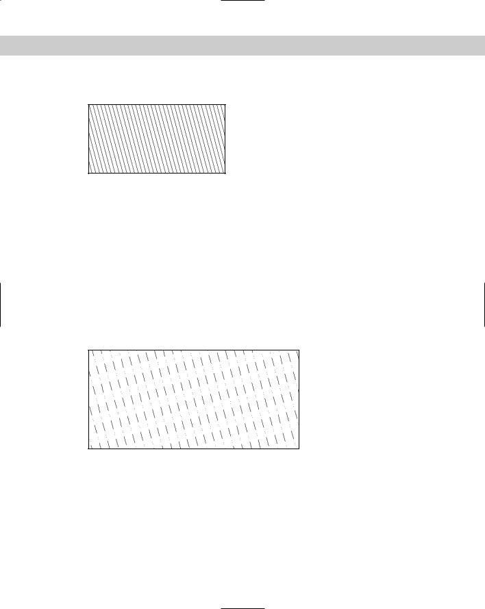
The hatch pattern shown in Figure 31-6 is the simplest form of hatch pattern.
Figure 31-6: The ftrailer hatch pattern with continuous lines.
Although you could specify this simple hatch pattern in the Boundary Hatch dialog box by specifying a user-defined hatch with an angle and spacing, the example that follows shows the syntax clearly. The lines are at an angle of 105 degrees; the hatch pattern starts at 0,0; and the spacing between the lines is 0.5 units. The lines are continuous.
*ftrailer, proposed future trailers 105, 0,0, 0,0.5
Adding one level of complexity, you can make the lines in the hatch pattern noncontinuous, as follows:
*ftrailer, proposed future trailers 105, 0,0, 0,0.5, .5,–.25,0,–.1,0,–.25
Note that this definition uses the maximum of six dash specifications (the dash, space, dot, space, dot, and space).
A close-up of this hatch pattern is shown in Figure 31-7.
Figure 31-7: The ftrailer hatch pattern with a dash and two dots.
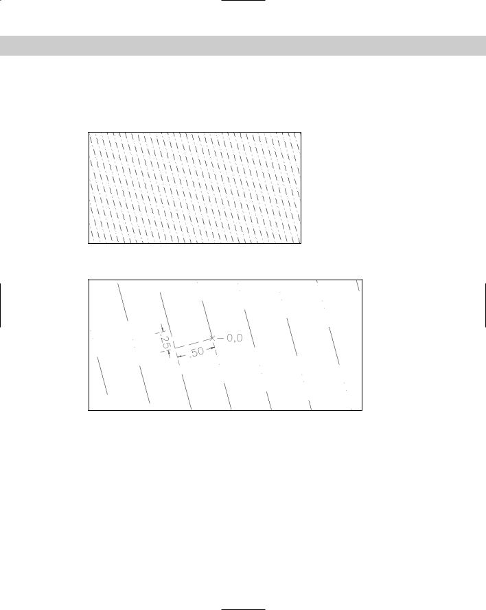
If you add a delta-x of 0.25, the lines in the pattern are staggered by 0.25 units, along the direction of the lines, as shown in this code and in Figure 31-8:
*ftrailer, proposed future trailers
105, 0,0, 0.25,0.5, .5,–.25,0,–.1,0,–.25
You might wonder why the pattern staggers downward after adding a positive delta-x. The answer is that the direction of the lines (in this case, 105 degrees) becomes the X axis for this
Chapter 31 Creating Your Own Linetypes and Hatch Patterns 929
calculation. Figure 31-9 shows a zoomed-in display of the hatch pattern around 0,0, which is the base point. The hatch pattern is being generated up and to the left. The first line starts at 0,0, and the second line starts to the left by 0.5 units (the delta-y) and up by 0.25 units (the delta-x), as shown by the dimensions.
Figure 31-8: The ftrailer hatch pattern with an added delta-x.
Figure 31-9: Calculating how the delta-x and delta-y affect a hatch pattern.
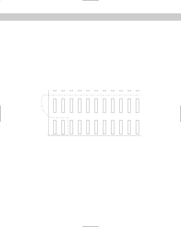
Finally, you can add additional definition lines. One of the definition lines should start at 0,0, but the others may start anywhere. Here is the definition for the pattern in Figure 31-10. It actually creates the shape of the trailers. Although you see the rectangular shape, the hatch pattern is created from four separate lines — two at 0 degrees and two at 90 degrees. Note that the two 0-degree lines are the same except that they start at different base points. The same is true for the two 90-degree lines.
*trail, |
whole trailers-proposed |
||||
0, |
0,0, |
0,2, |
.5,–1 |
||
90, |
0,0, |
|
0,1.5, .5,–.25,0,–.25,.5,–.5 |
||
90, |
.5,0, |
0,1.5, .5,–.25,0,–.25,.5,–.5 |
|||
0, |
0,1.5, |
0,2, |
.5,–1 |
||
930 Part VI Customizing AutoCAD
Figure 31-10: The trail hatch pattern looks like trailers.
STEP-BY-STEP: Creating and Using a Hatch Pattern
1.Open a drawing using any template.
2.Save the file as ab31-03.dwg in your AutoCAD Bible folder.
3.Type notepad and press Enter at the File to edit: prompt.
4.Type the following:
*lightning, interwoven lightning 90, 0,0, 0,.5, .5,–.25 0, –.25,.5, 0,.75, .25,–.25
90, –.25,.5, 0,.5, .5,–.25
5.Press Enter after the last line. Save the file as lightning.pat in your AutoCAD Bible folder. Close Notepad.
6.If you haven’t already done so, you need to add your AutoCAD Bible folder to the support-file search path. Choose Tools Options and click the Files tab. Click the plus sign to the left of Support File Search Path. Choose Add. Choose Browse. Find your AutoCAD Bible folder and click OK. Click OK again to close the Options dialog box.
7.Choose Rectangle from the Draw toolbar. At the first prompt, type 0,0 . At the
Specify other corner point or [Dimensions]: prompt, type 10,6 .
8.Choose Hatch from the Draw toolbar. In the Type drop-down list, choose Custom.
9.Click the ellipsis to the right of the Custom Pattern text box. Choose the lightning.pat file you just created. Click OK.
10.Choose Select Objects and pick the rectangle in your drawing. Press Enter. Click OK. The rectangle fills with the lightning hatch, as shown in Figure 31-11.
11.Save your drawing.