

- •Foreword
- •Preface
- •Is This Book for You?
- •How This Book Is Organized
- •How to Use This Book
- •Doing the Exercises
- •Conventions Used in This Book
- •What the Icons Mean
- •About the CD-ROM
- •Other Information
- •Contacting the Author
- •Acknowledgments
- •Contents at a Glance
- •Contents
- •Getting Acquainted with AutoCAD and AutoCAD LT
- •Starting AutoCAD and AutoCAD LT
- •Creating a New Drawing
- •Using the AutoCAD and AutoCAD LT Interface
- •Creating Your First Drawing
- •Saving a Drawing
- •Summary
- •Creating a New Drawing from a Template
- •Working with Templates
- •Opening a Drawing with Default Settings
- •Opening an Existing Drawing
- •Using an Existing Drawing as a Prototype
- •Saving a Drawing Under a New Name
- •Summary
- •The Command Line
- •Command Techniques
- •Of Mice and Pucks
- •Getting Help
- •Summary
- •Typing Coordinates
- •Displaying Coordinates
- •Picking Coordinates on the Screen
- •Locating Points
- •Summary
- •Unit Types
- •Drawing Limits
- •Understanding Scales
- •Inserting a Title Block
- •Common Setup Options
- •The MVSETUP Command
- •Summary
- •Using the LINE Command
- •Drawing Rectangles
- •Drawing Polygons
- •Creating Construction Lines
- •Creating Rays
- •Summary
- •Drawing Circles
- •Drawing Arcs
- •Creating Ellipses and Elliptical Arcs
- •Making Donuts
- •Placing Points
- •Summary
- •Panning
- •The ZOOM Command
- •Aerial View
- •Named Views
- •Tiled Viewports
- •Snap Rotation
- •User Coordinate Systems
- •Isometric Drawing
- •Summary
- •Editing a Drawing
- •Selecting Objects
- •Summary
- •Copying and Moving Objects
- •Using Construction Commands
- •Creating a Revision Cloud
- •Hiding Objects with a Wipeout
- •Double-Clicking to Edit Objects
- •Grips
- •Editing with the Properties Palette
- •Selection Filters
- •Groups
- •Summary
- •Working with Layers
- •Changing Object Color, Linetype, and Lineweight
- •Working with Linetype Scales
- •Importing Layers and Linetypes from Other Drawings
- •Matching Properties
- •Summary
- •Drawing-Level Information
- •Object-Level Information
- •Measurement Commands
- •AutoCAD’s Calculator
- •Summary
- •Creating Single-Line Text
- •Understanding Text Styles
- •Creating Multiline Text
- •Creating Tables
- •Inserting Fields
- •Managing Text
- •Finding Text in Your Drawing
- •Checking Your Spelling
- •Summary
- •Working with Dimensions
- •Drawing Linear Dimensions
- •Drawing Aligned Dimensions
- •Creating Baseline and Continued Dimensions
- •Dimensioning Arcs and Circles
- •Dimensioning Angles
- •Creating Ordinate Dimensions
- •Drawing Leaders
- •Using Quick Dimension
- •Editing Dimensions
- •Summary
- •Understanding Dimension Styles
- •Defining a New Dimension Style
- •Changing Dimension Styles
- •Creating Geometric Tolerances
- •Summary
- •Creating and Editing Polylines
- •Drawing and Editing Splines
- •Creating Regions
- •Creating Boundaries
- •Creating Hatches
- •Creating and Editing Multilines
- •Creating Dlines
- •Using the SKETCH Command
- •Digitizing Drawings with the TABLET Command
- •Summary
- •Preparing a Drawing for Plotting or Printing
- •Creating a Layout in Paper Space
- •Working with Plot Styles
- •Plotting a Drawing
- •Summary
- •Combining Objects into Blocks
- •Inserting Blocks and Files into Drawings
- •Managing Blocks
- •Using Windows Features
- •Working with Attributes
- •Summary
- •Understanding External References
- •Editing an Xref within Your Drawing
- •Controlling Xref Display
- •Managing Xrefs
- •Summary
- •Preparing for Database Connectivity
- •Connecting to Your Database
- •Linking Data to Drawing Objects
- •Creating Labels
- •Querying with the Query Editor
- •Working with Query Files
- •Summary
- •Working with 3D Coordinates
- •Using Elevation and Thickness
- •Working with the User Coordinate System
- •Summary
- •Working with the Standard Viewpoints
- •Using DDVPOINT
- •Working with the Tripod and Compass
- •Getting a Quick Plan View
- •Shading Your Drawing
- •Using 3D Orbit
- •Using Tiled Viewports
- •Defining a Perspective View
- •Laying Out 3D Drawings
- •Summary
- •Drawing Surfaces with 3DFACE
- •Drawing Surfaces with PFACE
- •Creating Polygon Meshes with 3DMESH
- •Drawing Standard 3D Shapes
- •Drawing a Revolved Surface
- •Drawing an Extruded Surface
- •Drawing Ruled Surfaces
- •Drawing Edge Surfaces
- •Summary
- •Drawing Standard Shapes
- •Creating Extruded Solids
- •Drawing Revolved Solids
- •Creating Complex Solids
- •Sectioning and Slicing Solids
- •Using Editing Commands in 3D
- •Editing Solids
- •Listing Solid Properties
- •Summary
- •Understanding Rendering
- •Creating Lights
- •Creating Scenes
- •Working with Materials
- •Using Backgrounds
- •Doing the Final Render
- •Summary
- •Accessing Drawing Components with the DesignCenter
- •Accessing Drawing Content with Tool Palettes
- •Setting Standards for Drawings
- •Organizing Your Drawings
- •Working with Sheet Sets
- •Maintaining Security
- •Keeping Track of Referenced Files
- •Handling Errors and Crashes
- •Managing Drawings from Prior Releases
- •Summary
- •Importing and Exporting Other File Formats
- •Working with Raster Images
- •Pasting, Linking, and Embedding Objects
- •Summary
- •Sending Drawings
- •Opening Drawings from the Web
- •Creating Object Hyperlinks
- •Publishing Drawings
- •Summary
- •Working with Customizable Files
- •Creating Keyboard Shortcuts for Commands
- •Customizing Toolbars
- •Customizing Tool Palettes
- •Summary
- •Creating Macros with Script Files
- •Creating Slide Shows
- •Creating Slide Libraries
- •Summary
- •Creating Linetypes
- •Creating Hatch Patterns
- •Summary
- •Creating Shapes
- •Creating Fonts
- •Summary
- •Working with Menu Files
- •Customizing a Menu
- •Summary
- •Introducing Visual LISP
- •Getting Help in Visual LISP
- •Working with AutoLISP Expressions
- •Using AutoLISP on the Command Line
- •Creating AutoLISP Files
- •Summary
- •Creating Variables
- •Working with AutoCAD Commands
- •Working with Lists
- •Setting Conditions
- •Managing Drawing Objects
- •Getting Input from the User
- •Putting on the Finishing Touches
- •Summary
- •Understanding Local and Global Variables
- •Working with Visual LISP ActiveX Functions
- •Debugging Code
- •Summary
- •Starting to Work with VBA
- •Writing VBA Code
- •Getting User Input
- •Creating Dialog Boxes
- •Modifying Objects
- •Debugging and Trapping Errors
- •Moving to Advanced Programming
- •A Final Word
- •Installing AutoCAD and AutoCAD LT
- •Configuring AutoCAD
- •Starting AutoCAD Your Way
- •Configuring a Plotter
- •System Requirements
- •Using the CD with Microsoft Windows
- •What’s on the CD
- •Troubleshooting
- •Index

Chapter 35 Exploring AutoLISP Further 1011
Here’s how this routine works. This discussion assumes you’ve already read the discussion of the previous routine, which was very similar.
First, you added a new variable, old_cmdecho, to the chgcolor function.
In the following line, you set this variable to the current value of the CMDECHO system variable. You obtained this current value using GETVAR.
You then used SETVAR to set the AutoCAD system variable CMDECHO to 0.
You may need to see the commands echoed for debugging purposes, so it would prove best to return CMDECHO to the value it was set to before running the routine. Therefore, in the last line you use SETVAR again to reset CMDECHO to the variable old_cmdecho, which stored the original value of CMDECHO.
As a result of these changes, the chgcolor program always sets the CMDECHO system variable back to the value it had before being run.
Working with Lists
Lists are the primary structures you work with while programming in AutoLISP. As you work in this chapter, you’ll begin to understand the use of lists to modify objects (also called entities) in the AutoCAD database, and in a variety of other contexts with AutoLISP. AutoCAD represents all object data in a list that contains many smaller lists, but the lists are simple to use and manipulate.
Using lists for coordinates
A list is always enclosed in parentheses with spaces between the elements of the list. One common use for lists is for coordinates, as shown in the following example:
(1.0 3.5 2.0)
This list represents the X,Y,Z coordinates 1.0,3.5,2.0. You often need to extract one or more of the elements in a list. Table 35-1 shows the common list-extraction functions using the example list (1.0 3.5 2.0).
Table 35-1: Basic List-Extraction Functions
Function |
Pronunciation |
Example Output |
Description |
|
|
|
|
CAR |
car |
1.0 |
Returns the first element in a list |
CDR |
could-er |
(3.5 2.0) |
Removes the first element from a list |
CADR |
cad-er |
3.5 |
Returns the second element in a list |
CADDR |
ca-did-der |
2.0 |
Returns the third element in a list |
|
|
|
|

1012 Part VII Programming AutoCAD
For more flexibility, you can use the NTH function. Use the NTH function to access any element in a list by passing two arguments that specify the number of the element (items are numbered starting from 0) and the list that you want.
The name of the list is usually a variable set with SETQ:
(setq corner (list 1.0 3.5 2.0))
In this example, (nth 0 corner) returns 1.0 because 1.0 is the first item in the list corner.
The LIST function creates a list. If all the items in a list are constant values (not variables), you can use the QUOTE function to create a list. You can use a single quote (the same as an apostrophe on the keyboard) as a shortcut for the QUOTE function. The following two functions are equivalent:
(setq corner (list 1.0 3.5 2.0)) (setq corner ‘(1.0 3.5 2.0))
Many more AutoLISP list-extraction functions are detailed in the AutoLISP Function Synopsis Appendix of the Visual LISP Developer’s Guide. Look under Basic Functions, then List Manipulation Functions. You can go a long way by remembering the functions listed here.
Creating dotted pairs
A dotted pair is a special type of list that contains only two elements. Some AutoLISP functions do not accept dotted pairs as an argument, but they’re used to represent AutoCAD database objects. To construct a dotted pair, use the CONS function:
(cons 2.1 4.5)
This example returns (2.1 . 4.5). This list type is known as a dotted pair because it contains exactly two elements, and the elements are separated by a period or dot.
STEP-BY-STEP: Working with AutoLISP Lists
1.Start a new drawing using the acad.dwt template.
2.Choose Tools AutoLISP Visual LISP Editor to open Visual LISP.
3.In the Visual LISP Console window, type (setq endpt '(3.5 2.0 1.4)) . AutoLISP returns
(3.5 2.0 1.4).
4.Continue in the Visual LISP Console. Type (car endpt) . AutoLISP returns 3.5.
5.Type (cadr endpt) . AutoLISP returns 2.0.
6.Type (cdr endpt) . AutoLISP returns (2.0 1.4).
7.Type (nth 1 endpt) . AutoLISP returns 2.0.
Don’t save your drawing.
Setting Conditions
Often, you want to execute a procedure based on a certain condition. One way of doing this is with the IF statement, which does one thing if a statement is true and another thing if it’s false. In other words, the operation is conditioned on the truth of a certain statement.

Chapter 35 Exploring AutoLISP Further 1013
Looping is an important part of programming. Frequently, you want to execute a procedure over and over until the routine has finished operating on all the target objects or items. Looping sets up the condition that determines when the operation starts, the number of objects upon which the routine operates, and when the operation ends.
Conditional structures
Conditional structures enable program flow to be determined based on the outcome of a given decision. These decisions result in the return of either T, meaning true, or nil, meaning false. To try out the following statements, type them in the Visual LISP Console window. For instance, for the statement
(< 3 5) T
AutoLISP returns T for true, having determined that 3 is less than 5. For the statement
(> 3 5) nil
AutoLISP returns nil for false, having determined that 3 is not greater than 5. For the statement
(= 3 5) nil
AutoLISP returns nil. Here, we’ve determined that 3 is not equal to 5. Because these statements return either T or nil, you can use the IF statement. The general syntax of the IF statement is (if conditional-test if-true if-false).
Say you want to find circles whose radius is less than 0.25. Here’s a sample IF statement. In this example, radius is a variable that has been previously set.
(if (< radius .25)
(princ “The radius is less than .25”) (princ “The radius is not less than .25”)
)
The conditional test is (< radius .25). The if-true statement is (princ “The radius
is less than .25”). The if-false statement is (princ “The radius is not less than
.25”). This IF statement is equivalent to saying, “If the radius is less than .25, print ‘The radius is less than .25’ but if not, print ‘The radius is not less than .25.’”
You can leave out the if-false statement. Then AutoLISP executes the if-true statement if the conditional statement is true and does nothing if it’s false, and continues to the rest of the program. In the following exercise, you see both types of IF statements, one nested inside the other.
STEP-BY-STEP: Using the IF Statement
1.Start a new drawing in AutoCAD using the acad.dwt template.
2.Open Visual LISP, start a new file, and type the following:
(defun c:compare2three (/ entered_num)
(setq entered_num (getint “\nEnter an integer: “)) (if (< entered_num 3)

1014 Part VII Programming AutoCAD
(princ “\nThe entered number is less than 3.”) (if (= entered_num 3)
(princ “\nThe entered number is equal to 3.”) (princ “\nThe entered number is greater than 3.”)
)
)
(princ)
)
The GETINT function gets an integer from the user and is covered later in this chapter. The \n before the Enter an integer: prompt starts a new line; it’s similar to using (terpri). Using (princ) at the end of a routine is also covered later in this chapter.
3.Choose Check Edit Window. If you see any error message in the Build Output window, check your typing, make any necessary correction, and try again.
4.Save the file as ab35-02.lsp in a folder that is in the support-file search path, or in
AutoCAD 2005\Support.
5.Choose Load Active Edit Window and then choose Activate AutoCAD.
6.To try out the IF statement, type compare2three . At the Enter an integer:
prompt, type 5 . AutoCAD displays: The entered number is greater than 3.
7.Repeat the COMPARE2THREE command. At the Enter an integer: prompt, type 3 .
AutoCAD displays: The entered number is equal to 3.
8.Repeat the COMPARE2THREE command. At the Enter an integer: command, type
2 . AutoCAD displays: The entered number is less than 3.
Don’t save your drawing.
Loop structures
Looping provides the capability to execute a step or a number of steps a given number of times based on an evaluation you make in your application. One way to do this is with the WHILE function.
The format of the WHILE function is:
(while conditional-test-if-true then-perform-the-following-code-until-the condition-is-false)
One method that can be useful with a WHILE conditional-test-if-true is to include a counter for the WHILE expression. A counter counts how many times an operation is executed. You can then end the operation when the counter reaches a certain number. To create a counter, set a variable (perhaps named “counter”) to the number at which you want to start. Then write the code for one pass through the operation. Then set the counter to the next higher number using an expression, such as the following:
(setq counter (+ 1 counter))
The routine then loops back over the operation until the counter reaches the value you set.
Here’s a simple example:

Chapter 35 Exploring AutoLISP Further 1015
(defun c:process (/ counter) (setq counter 1)
(while (< counter 6)
(princ “Processing number “) (princ counter)
(terpri)
(setq counter (+ 1 counter))
)
)
In this example, the process function starts by setting the variable counter to 1. Then you start the WHILE statement and specify that the counter must be less than 6. Within the WHILE statement, you print the text string “Processing number” and then the value of the counter variable. You use (terpri) so that each text string starts on a new line. Then you set the counter to the next higher number. Each time through the WHILE loop, the value of the counter is incremented by 1. Without the increment statement, line 3 would always evaluate to true and the WHILE loop would never exit because the counter would always be 1.
If you accidentally program an infinite loop like this, you can stop the execution of your AutoLISP routine by pressing Esc, pressing Ctrl+Break, or choosing Debug Abort Evaluation from the Visual LISP menu.
In the preceding example, the WHILE loop continues as long as the counter is less than 6. When the counter reaches 6, the routine stops. The WHILE statement returns the last value of the routine, so AutoCAD prints 6 on the last line. Figure 35-3 shows the result.
Figure 35-3: The result of the process function.
When using WHILE, you may want to combine several operations under the condition. The IF function normally evaluates one then expression if the test expression is true. Suppose you want an IF expression that processes various tasks if the test condition is true. An IF expression, as previously mentioned, processes a “do-if-true” and “do-if-false.” Therefore, to process more than one “do-if true” expression, you need to separate the “do-if-true” processes from the “do-if-false” processes. To accomplish this, use PROGN (short for program nest) to include (or nest) all items you want executed when the test is true. In general, PROGN evaluates all the statements within its parentheses and returns the last evaluation as if it were one statement, as the following example demonstrates.
In the next example, you see the same IF statements used in an earlier example. However, after the second IF statement, you want your routine to print two lines if the entered number equals 3. You can do this by enclosing the two lines of code (plus a terpri) within a PROGN statement:
(defun c:compare2three (/ entered_num)
(setq entered_num (getint “\nEnter an integer: “)) (if (< entered_num 3)
(princ “\nThe entered number is less than 3.”)
1016 Part VII Programming AutoCAD
On the
CD-ROM
(if (= entered_num 3) (progn
(princ “\nThe entered number is equal to 3.”) (terpri)
(princ “\nThis is the one we are looking for.”)
)
(princ “\nThe entered number is greater than 3.”)
)
)
(princ)
)
The file used in the following Step-by-Step exercise on using WHILE, IF, PROGN, and a counter, ab35-b.lsp, is in the Drawings folder on the CD-ROM.
STEP-BY-STEP: Using WHILE, IF, PROGN, and a Counter
1.Open AutoCAD with any new drawing.
2.Open Visual LISP.
3.Click Open File on the Visual LISP Standard toolbar and open ab35-b.lsp from the CD-ROM.
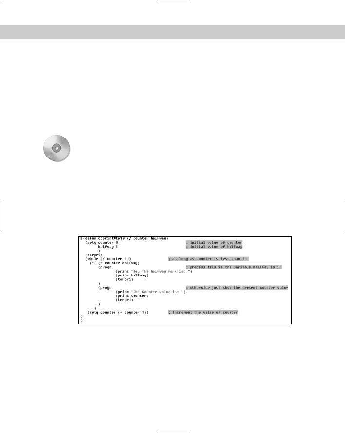
4.Save the file as ab35-03.lsp in AutoCAD 2005\Support or any folder in the supportfile search path. Figure 35-4 shows this routine.
Figure 35-4: The print0to10 routine.
5.Load ab35-03.lsp. Return to AutoCAD.
6.Type print0to10 . Press F2 to open the AutoCAD Text Window and see the result, shown in Figure 35-5.