

- •Foreword
- •Preface
- •Is This Book for You?
- •How This Book Is Organized
- •How to Use This Book
- •Doing the Exercises
- •Conventions Used in This Book
- •What the Icons Mean
- •About the CD-ROM
- •Other Information
- •Contacting the Author
- •Acknowledgments
- •Contents at a Glance
- •Contents
- •Getting Acquainted with AutoCAD and AutoCAD LT
- •Starting AutoCAD and AutoCAD LT
- •Creating a New Drawing
- •Using the AutoCAD and AutoCAD LT Interface
- •Creating Your First Drawing
- •Saving a Drawing
- •Summary
- •Creating a New Drawing from a Template
- •Working with Templates
- •Opening a Drawing with Default Settings
- •Opening an Existing Drawing
- •Using an Existing Drawing as a Prototype
- •Saving a Drawing Under a New Name
- •Summary
- •The Command Line
- •Command Techniques
- •Of Mice and Pucks
- •Getting Help
- •Summary
- •Typing Coordinates
- •Displaying Coordinates
- •Picking Coordinates on the Screen
- •Locating Points
- •Summary
- •Unit Types
- •Drawing Limits
- •Understanding Scales
- •Inserting a Title Block
- •Common Setup Options
- •The MVSETUP Command
- •Summary
- •Using the LINE Command
- •Drawing Rectangles
- •Drawing Polygons
- •Creating Construction Lines
- •Creating Rays
- •Summary
- •Drawing Circles
- •Drawing Arcs
- •Creating Ellipses and Elliptical Arcs
- •Making Donuts
- •Placing Points
- •Summary
- •Panning
- •The ZOOM Command
- •Aerial View
- •Named Views
- •Tiled Viewports
- •Snap Rotation
- •User Coordinate Systems
- •Isometric Drawing
- •Summary
- •Editing a Drawing
- •Selecting Objects
- •Summary
- •Copying and Moving Objects
- •Using Construction Commands
- •Creating a Revision Cloud
- •Hiding Objects with a Wipeout
- •Double-Clicking to Edit Objects
- •Grips
- •Editing with the Properties Palette
- •Selection Filters
- •Groups
- •Summary
- •Working with Layers
- •Changing Object Color, Linetype, and Lineweight
- •Working with Linetype Scales
- •Importing Layers and Linetypes from Other Drawings
- •Matching Properties
- •Summary
- •Drawing-Level Information
- •Object-Level Information
- •Measurement Commands
- •AutoCAD’s Calculator
- •Summary
- •Creating Single-Line Text
- •Understanding Text Styles
- •Creating Multiline Text
- •Creating Tables
- •Inserting Fields
- •Managing Text
- •Finding Text in Your Drawing
- •Checking Your Spelling
- •Summary
- •Working with Dimensions
- •Drawing Linear Dimensions
- •Drawing Aligned Dimensions
- •Creating Baseline and Continued Dimensions
- •Dimensioning Arcs and Circles
- •Dimensioning Angles
- •Creating Ordinate Dimensions
- •Drawing Leaders
- •Using Quick Dimension
- •Editing Dimensions
- •Summary
- •Understanding Dimension Styles
- •Defining a New Dimension Style
- •Changing Dimension Styles
- •Creating Geometric Tolerances
- •Summary
- •Creating and Editing Polylines
- •Drawing and Editing Splines
- •Creating Regions
- •Creating Boundaries
- •Creating Hatches
- •Creating and Editing Multilines
- •Creating Dlines
- •Using the SKETCH Command
- •Digitizing Drawings with the TABLET Command
- •Summary
- •Preparing a Drawing for Plotting or Printing
- •Creating a Layout in Paper Space
- •Working with Plot Styles
- •Plotting a Drawing
- •Summary
- •Combining Objects into Blocks
- •Inserting Blocks and Files into Drawings
- •Managing Blocks
- •Using Windows Features
- •Working with Attributes
- •Summary
- •Understanding External References
- •Editing an Xref within Your Drawing
- •Controlling Xref Display
- •Managing Xrefs
- •Summary
- •Preparing for Database Connectivity
- •Connecting to Your Database
- •Linking Data to Drawing Objects
- •Creating Labels
- •Querying with the Query Editor
- •Working with Query Files
- •Summary
- •Working with 3D Coordinates
- •Using Elevation and Thickness
- •Working with the User Coordinate System
- •Summary
- •Working with the Standard Viewpoints
- •Using DDVPOINT
- •Working with the Tripod and Compass
- •Getting a Quick Plan View
- •Shading Your Drawing
- •Using 3D Orbit
- •Using Tiled Viewports
- •Defining a Perspective View
- •Laying Out 3D Drawings
- •Summary
- •Drawing Surfaces with 3DFACE
- •Drawing Surfaces with PFACE
- •Creating Polygon Meshes with 3DMESH
- •Drawing Standard 3D Shapes
- •Drawing a Revolved Surface
- •Drawing an Extruded Surface
- •Drawing Ruled Surfaces
- •Drawing Edge Surfaces
- •Summary
- •Drawing Standard Shapes
- •Creating Extruded Solids
- •Drawing Revolved Solids
- •Creating Complex Solids
- •Sectioning and Slicing Solids
- •Using Editing Commands in 3D
- •Editing Solids
- •Listing Solid Properties
- •Summary
- •Understanding Rendering
- •Creating Lights
- •Creating Scenes
- •Working with Materials
- •Using Backgrounds
- •Doing the Final Render
- •Summary
- •Accessing Drawing Components with the DesignCenter
- •Accessing Drawing Content with Tool Palettes
- •Setting Standards for Drawings
- •Organizing Your Drawings
- •Working with Sheet Sets
- •Maintaining Security
- •Keeping Track of Referenced Files
- •Handling Errors and Crashes
- •Managing Drawings from Prior Releases
- •Summary
- •Importing and Exporting Other File Formats
- •Working with Raster Images
- •Pasting, Linking, and Embedding Objects
- •Summary
- •Sending Drawings
- •Opening Drawings from the Web
- •Creating Object Hyperlinks
- •Publishing Drawings
- •Summary
- •Working with Customizable Files
- •Creating Keyboard Shortcuts for Commands
- •Customizing Toolbars
- •Customizing Tool Palettes
- •Summary
- •Creating Macros with Script Files
- •Creating Slide Shows
- •Creating Slide Libraries
- •Summary
- •Creating Linetypes
- •Creating Hatch Patterns
- •Summary
- •Creating Shapes
- •Creating Fonts
- •Summary
- •Working with Menu Files
- •Customizing a Menu
- •Summary
- •Introducing Visual LISP
- •Getting Help in Visual LISP
- •Working with AutoLISP Expressions
- •Using AutoLISP on the Command Line
- •Creating AutoLISP Files
- •Summary
- •Creating Variables
- •Working with AutoCAD Commands
- •Working with Lists
- •Setting Conditions
- •Managing Drawing Objects
- •Getting Input from the User
- •Putting on the Finishing Touches
- •Summary
- •Understanding Local and Global Variables
- •Working with Visual LISP ActiveX Functions
- •Debugging Code
- •Summary
- •Starting to Work with VBA
- •Writing VBA Code
- •Getting User Input
- •Creating Dialog Boxes
- •Modifying Objects
- •Debugging and Trapping Errors
- •Moving to Advanced Programming
- •A Final Word
- •Installing AutoCAD and AutoCAD LT
- •Configuring AutoCAD
- •Starting AutoCAD Your Way
- •Configuring a Plotter
- •System Requirements
- •Using the CD with Microsoft Windows
- •What’s on the CD
- •Troubleshooting
- •Index
Chapter 25 Rendering in 3D 759
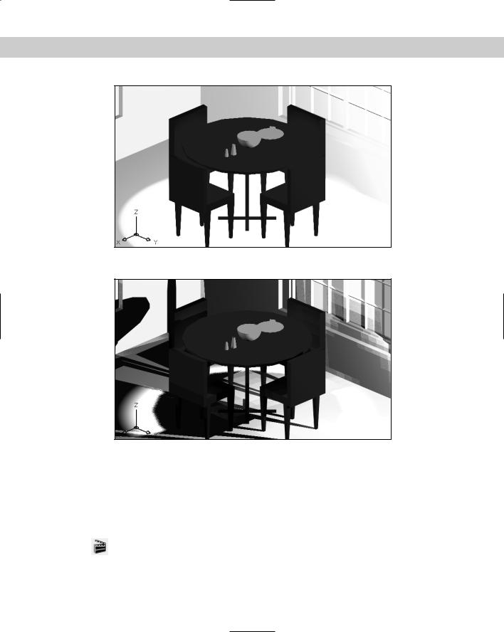
Figure 25-13: A rendering with lights but no shadows.
Figure 25-14: The same rendering with shadows.
Creating Scenes
Scenes help you manage lights and views. For example, you can create two scenes — the first with only a distant light to mimic the effect of exclusively natural light, and another with no distant light but with point lights and spotlights to create a nighttime effect. You can also change the view so that you can look at the objects from different vantage points.
To create a scene, choose Scenes from the Render toolbar to open the Scenes dialog box, shown in Figure 25-15.This dialog box lists your scenes and enables you to create,
modify, and delete scenes.
760 Part IV Drawing in Three Dimensions
Figure 25-15: The Scenes dialog box.
To create a new scene, follow these steps:
1.Click New to open the New Scene dialog box, shown in Figure 25-16. The New Scene dialog box lists all the saved views and all the lights you’ve created.
Figure 25-16: The New Scene dialog box.
2.Type a name in the Scene Name text box, no more than eight characters long.
3.Choose a view. You can choose only one.
4.Choose the lights you want. Press Ctrl to choose more than one light. Press Shift to choose a range of lights. You can also choose *ALL* to quickly choose all the lights for the scene.
5.Click OK.
Your scene is now listed in the Scenes dialog box. Click OK again to return to your drawing. When you render the drawing, you can choose this scene from the Render dialog box.
On the |
The drawing used in the following Step-by-Step exercise on creating a scene, ab25-2.dwg, |
CD-ROM |
is in the Results folder on the CD-ROM. |
Chapter 25 Rendering in 3D 761
STEP-BY-STEP: Creating a Scene
1.If you have ab25-02.dwg open, use it. Otherwise, open it from your AutoCAD Bible folder or the Results folder on the CD-ROM.
2.Save the file as ab25-03.dwg in your AutoCAD Bible folder. If the Render toolbar is not open, right-click any toolbar and choose Render.
3.Choose Scenes from the Render toolbar. Click New in the Scenes dialog box to open the New Scene dialog box.
4.Type morning in the Scene Name text box.
5.Choose RENDER1 from the Views list.
6.Choose D1 and P1 from the Lights list, pressing the Ctrl key while you select the second light.
7.Click OK twice to return to the drawing.
8.Save the drawing. If you’re continuing on to the next Step-by-Step exercise, keep it open.
Working with Materials
Working with materials involves two steps — adding them to the drawing and attaching them to objects. Designing appropriate materials is an important part of the rendering process and greatly affects the results. Materials interact with lights. For example, shiny materials reflect light differently than dull materials because shiny materials create highlights. The object’s color affects how light appears on it as well.
Adding materials
AutoCAD comes with a large selection of materials. You can modify these to create your own materials. To add materials to the drawing, choose Materials Library from the
Render toolbar to open the Materials Library dialog box, shown in Figure 25-17.
Working with lists of materials
Materials are saved in a file with the extension .mli (materials library). The default materials library is render.mli. The left side of the Materials Library dialog box represents materials in the current drawing. The right side of the dialog box represents the entire list of materials provided by AutoCAD.
In the Current Drawing section, you can:
Click Save As to save the list of materials in the current drawing in an MLI file.
Click Purge to delete all the materials in the list from the drawing.

762 Part IV Drawing in Three Dimensions
Figure 25-17: The Materials Library dialog box.
In the Current Library section, you can:
Click Save to save changes to the entire library list in the MLI file in the current folder.
Click Save As to save the entire current library list in a new MLI file in any location.
Click Open to open a different library list and use its materials.
Importing and previewing materials
You often work with existing materials, but should preview them first to make sure that they meet your needs. To add existing materials to your drawing, follow these steps:
1.Choose a material from the Current Library list on the right side of the dialog box.
2.Click Import.
3.Choose the material from the Current Drawing list.
4.From the Preview drop-down list, choose the preview type of either Cube or Sphere, based on whether the object you want to use the material for is flat or curved.
5.Click Preview to see a sample of the material.
6.Repeat Steps 1 through 5 until you have all the materials you want.
7.Click OK.
Tip |
If you don’t find the exact material you want, import the closest one you can find. You can |
|
then create a new material based on that material. The next section explains how to edit |
|
existing materials. |
|
You can choose a range of materials by holding down Shift and clicking the first and last |
|
materials in the range. You can choose any nonconsecutive materials by holding down Ctrl |
|
and clicking the materials you want. |
|
If you don’t like a material that you’ve imported, highlight it and click Delete. Use the Export |
|
option to save materials you’ve created in the drawing to the materials library file. When you |
|
click OK to close the Materials Library dialog box, AutoCAD asks you if you want to save the |
|
changes you’ve made to the materials library file. Saving the changes updates the file. |
Chapter 25 Rendering in 3D 763
On the |
The drawing used in the following Step-by-Step exercise on importing materials, |
CD-ROM |
ab25-03.dwg, is in the Results folder on the CD-ROM. |
STEP-BY-STEP: Importing Materials
1.If you have ab25-03.dwg open from the previous exercise, use it. Otherwise, open it from your AutoCAD Bible folder (if you did the exercise) or the Results folder of the CD-ROM.
2.Save the file as ab25-04.dwg in your AutoCAD Bible folder. If the Render toolbar is not open, right-click any toolbar and choose Render.
3.Choose Materials Library from the Render toolbar. Hold down Ctrl, and scroll as necessary to choose Beige Plastic, Green Glass, Light Wood Tile, Pink Marble,
Stitched Pattern, White Matte, Wood Med. Ash, Wood White Ash, and Yellow Plastic. Click Import.
4.From the left list, choose Pink Marble. Choose Cube from the Preview drop-down list and click Preview to see the result. Do the same with Stitched Pattern.
5.Preview Green Glass with the Sphere.
6.Click OK. Save your drawing. If you’re continuing to the next Step-by-Step exercise, keep the drawing open.
Creating your own materials
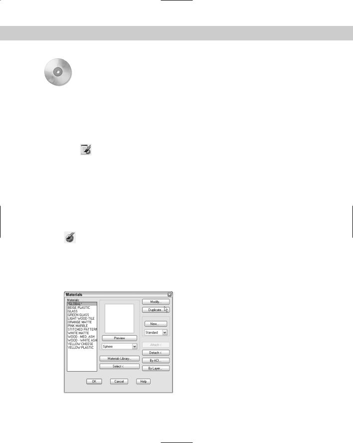
After you import materials from the materials library, you can modify them to create your own materials. Choose Materials from the Render toolbar to open the Materials
dialog box, shown in Figure 25-18.
Notice that you can click Materials Library in this dialog box to open the Materials Library dialog box. You can therefore use the Materials dialog box to manage the entire process of importing, creating, and attaching materials. You can preview imported materials in this dialog box as well.
Figure 25-18: The Materials dialog box.
764 Part IV Drawing in Three Dimensions
When you create a new material, you have three choices:
You can modify an existing material.
You can duplicate an existing material and then make modifications to the copy, leaving the original material intact.
You can start from scratch and create an entirely new material.
The dialog box that AutoCAD opens when you choose one of the preceding options depends on what you choose from the drop-down list below the New button. You have four choices: standard, marble, granite, and wood.
Standard creates a standard material.
Marble creates a material that mimics marble. In this dialog box you specify turbulence and sharpness of the veins as well as scale of the veins to the entire object of marble.
Granite creates a material that mimics granite. In this dialog box, you can specify up to four colors and their sharpness (distinctness) as well as the scale of the texture relative to the entire granite object.
Wood creates a material that mimics wood. In this dialog box, you specify the light/ dark ratio of the grain, the ring density and width, and the scale of the rings relative to the entire wood object.
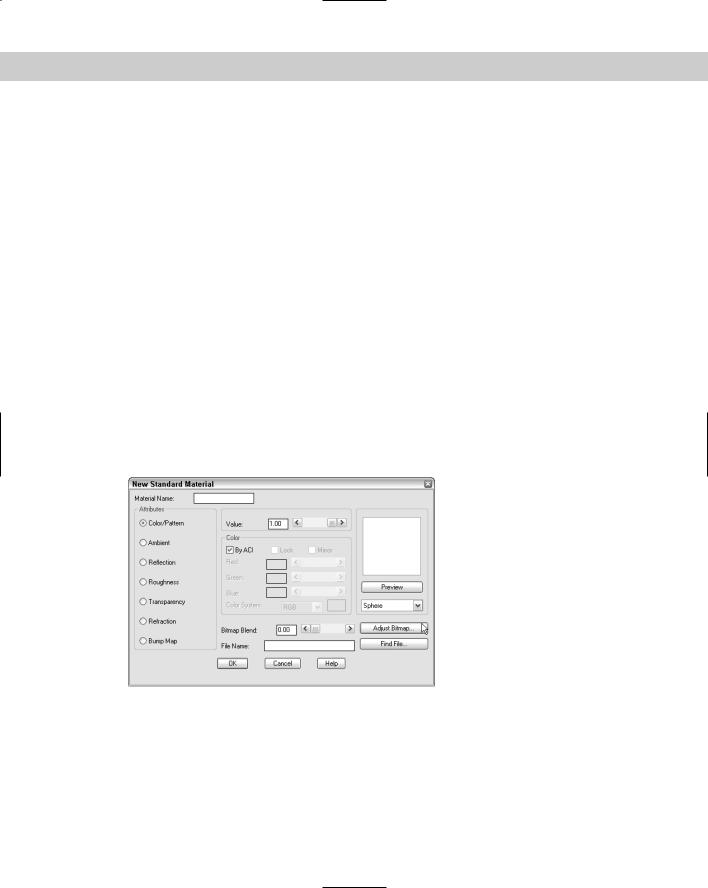
When you choose a method of creating a new material, whether by modifying, duplicating, or creating from scratch, AutoCAD opens the dialog box appropriate to the material you’ve chosen. Figure 25-19 shows the New Standard Material dialog box.
Figure 25-19: The New Standard Material dialog box.
Unless you’re modifying an existing material, you first give the material a name in the Material Name text box.
You use this dialog box by choosing the attributes listed on the left side one by one and then specifying the values for each attribute from the choices on the right.

Chapter 25 Rendering in 3D 765
Color/Pattern
The color is the basic color of the object. The reflection of light off the object (called diffuse reflection) is determined by this color. You set the color in the Color section of the dialog box, using one of four methods:
Choose By ACI (AutoCAD Color Index). This option enables you to set the color to the color of the object in the drawing. You must uncheck this to choose one of the three other methods.
Choose RGB from the Color System drop-down list to specify the color using the red- green-blue system. These are the three primary light colors. For each color you can type in a value from 0 to 1 or use the slider bars. When all three are set to 1, you get white light.
Choose HLS from the Color System drop-down list to specify the color using the hue, lightness, and saturation system. Hue is the color; lightness — or brightness — is the amount of white the color contains; saturation is the amount of black the color contains.
Click the color swatch to open the Windows Color dialog box, letting you specify a color using either the RGB or the HLS system.
In addition to setting the color, you set the value. The value affects the surface finish and interacts with the reflection value. For example, AutoCAD recommends using a color value of 0.7 and a reflection value of 0.3 for a dull finish and reversing the values for a shiny finish. You can type a value or use the slider bar. If you choose a bitmap (raster) file, the color becomes a pattern. See the “Mapping” sidebar for more information.
Ambient
The Ambient color and value affect the color reflected by ambient light. Remember that you set the amount of ambient light when you created lights. You can click the Lock check box in the Color section of the dialog box to lock the ambient and reflection colors to the main color. (You cannot use Lock if you checked By ACI as the color.)
Reflection
The reflection setting affects highlights created by light that shines on the object. To create a shiny object, you can use a reflection value of 0.7 with a color value of 0.3. Shiny objects often create a white highlight — for this effect, set the color to white by setting red, green, and blue to 1. You can also choose a bitmap file to create a reflection map. See the “Mapping” sidebar for more information.
Roughness
Roughness has no color setting — you only set a value. A rough surface produces smaller highlights. Use a lower value to create smaller highlights. If you chose a zero value for reflection, the roughness setting is not used.
Transparency
The transparency setting enables you to create transparent or translucent materials. You set the value from 0 to 1. Higher values mean greater transparency. Using transparency increases rendering time. You can choose a bitmap to create an opacity map. See the “Mapping” sidebar for more information.

766 Part IV Drawing in Three Dimensions
Mapping
AutoCAD lets you project a 2D image onto the surface of a 3D object. This is called mapping. You must use the Photo Real or Photo Raytrace rendering types to render with mappings. The 2D images are bitmap (raster) files that can be in several file formats, such as TGA, BMP, TIF, and JPEG. AutoCAD provides a large number of TGA files. To locate them, choose Tools Options and click the Files tab. Double-click Texture Maps Search Path. (You need to do a full or custom installation of AutoCAD to get all the texture maps.) You can actually place up to four bitmaps onto an object. When you create a material, you can add bitmaps to the Color/Pattern, Reflection, Transparency, and Bump Map characteristics of a material.
Four kinds of maps correspond to the four characteristics:
Texture maps place a pattern of colors onto the object. When you include a bitmap in the Color/Pattern definition, you turn a plain color into a pattern.
Reflection maps place a scene on the surface of a reflective object, in the same way that you can see yourself reflected in a pool of water. Add a bitmap to the Reflection definition.
Opacity maps mimic areas of opacity and transparency. Add a bitmap to the Transparency definition.
Bump maps create the effect of varying heights. Choose Bump Maps and choose a bitmap file.
AutoCAD comes with a number of materials that include maps. In the Materials Library dialog box, check out the Bumpywhite stone and Checker textures, for example. As their names make clear, the first material is a bump map and the second a texture map. Import and preview them to see how they look. Using these materials saves you the task of specifying a bitmap file.
Bitmap Blend determines how much the bitmap is used. The values range from 0 (zero) to 1. For example, a 1.0 value for a bump map gives you the full value of the bumps. A lower value creates lower bumps.
Choose Adjust Bitmap to open the Adjust Material Bitmap Placement dialog box. Here you set the offset of the origin of the bitmap and the scale. The scale is the number of times the bitmap fits onto the object. If you’re unfamiliar with the bitmap, you’ll need to experiment. You can try various options and click Preview to see the results. Bitmapping uses U and V axes, which are like X and Y axes but can have any direction and origin. Click Maintain Aspect Ratio to keep the U and V scales equal.
By default, bitmaps are tiled, which means that if the scale is less than 1, AutoCAD repeats the pattern to cover the entire object. You can also crop, which creates a decal effect — the pattern is placed just once on the object.
Refraction
Refraction only applies to Photo Raytrace rendering when you have a transparent (or translucent) material. Refraction is the bending of a light wave when it passes through an object to an object of another density. A higher value increases the refraction.
Bump Map
Bump maps create the effect of varying heights on the surface of the object — in other words, bumps. You use the bottom part of the dialog box to choose the bump map and for bump-map settings. See the “Mapping” sidebar for more information about bump maps.

Chapter 25 Rendering in 3D 767
As you complete the dialog box, you can click Preview and see the result as a sphere or cube at any time. When you like the results you see with Preview, click OK.
On the |
The drawing used in the following Step-by-Step exercise on creating materials, ab25-04.dwg, |
CD-ROM |
is in the Results folder on the CD-ROM. |
STEP-BY-STEP: Creating Materials
1.If you have ab25-04.dwg open from the previous exercise, use it. Otherwise, open it from your AutoCAD Bible folder (if you did the exercise) or the Results folder of the CD-ROM.
2.Save the file as ab25-05.dwg in your AutoCAD Bible folder. If the Render toolbar is not open, right-click any toolbar and choose Render.
3.Choose Materials from the Render toolbar. The materials that were imported in the previous Step-by-Step exercise are listed on the left. Choose Yellow Plastic and click Duplicate.
4.In the Material Name text box of the New Standard Material dialog box, type Yellow
Cheese.
5.With Color/Pattern selected from the Attributes section of the dialog box, click the color swatch to the right of the Color System drop-down list. In the Color dialog box, click the Index Color tab and pick the yellow box. Click OK.
6.Choose Ambient from the Attributes section. Click Lock in the Color section. The color changes to the same yellow as the Color/Pattern swatch.
7.Choose Reflection. Change the value to 0.10 because cheese isn’t very shiny. Click Lock here as well.
8.Choose Roughness. Change the value to 0.75.
You can omit transparency because its default value is 0 (zero). Refraction is irrelevant without a transparency setting.
9.Omit this step and Step 10 if you don’t have a full installation or a custom installation that includes textures. Preview the yellow cheese on a cube. Choose Bump Map from the Attributes section. Choose Find File at the bottom right of the dialog box. In the Bitmap File dialog box, the Textures folder should be current. (If not, find the Textures folder inside the main AutoCAD folder and double-click.) Change the Files of Type drop-down list to *.tga. Choose bmps.tga and click Open. Change the Bitmap Blend to .30. Click Preview again to see the difference. Note that the bumps are too big.
10.Click Adjust Bitmap. In the Adjust Bitmap Material Placement dialog box, check Maintain Aspect Ratio. Change the scale to 2 and click Preview using the cube. The bumps are smaller now. Click OK three times to return to your drawing.
11.Save your drawing.

768 Part IV Drawing in Three Dimensions
Attaching materials
After you import, create, and modify the materials you need, you can attach them to objects. AutoCAD lets you attach materials by object, layer, or color. To attach any material, follow these steps:
1.Choose Materials from the Render toolbar.
2.Choose the material from the list of materials.
3.Use one of these methods to attach the material:
•Click Attach to attach a material by selecting the object or objects. AutoCAD temporarily returns you to your drawing and prompts you to select objects.
•Click By ACI (AutoCAD Color Index) to attach a material by its color in the drawing. AutoCAD opens the Attach by AutoCAD Color Index dialog box, which lets you choose a color, or colors, by their numbers.
•Click By Layer to attach a material by layer. AutoCAD opens the Attach by Layer dialog box, which lets you choose a layer or layers.
Tip Attaching materials by layer can be a very efficient method. It requires some planning in advance. For example, if you have a block that is a chair, and if you create it so that the legs are on one layer and the seat and back are on a second layer, then you can easily attach a wood-like material to the legs and a decorative pattern to the seat and back.
You can assign a material to an object, to its layer, and to its color, which would mean that the object has three materials. AutoCAD gives priority to direct attachments by object, then to attachments by color, and finally to attachments by layer.
On the |
The drawing used in the following Step-by-Step exercise on attaching materials, ab25-b.dwg, |
CD-ROM |
is in the Drawings folder on the CD-ROM. |
STEP-BY-STEP: Attaching Materials
1.Open ab25-b.dwg from the CD-ROM.
2.Save the file as ab25-06.dwg in your AutoCAD Bible folder. If the Render toolbar is not open, right-click any toolbar and choose Render. This is the same drawing used earlier in the chapter, but all the materials have been imported and modified, and some materials have been attached to objects. Also, the table and chairs have been separated into appropriate layers.
3.Choose Materials from the Render toolbar. Click By Layer. In the Attach by Layer dialog box, choose PINK MARBLE from the Select a Material list. Choose TABLE_TOP from the Select Layer list. Click Attach. The PINK MARBLE material appears next to the
TABLE_TOP layer.
4.Choose STITCHED PATTERN from the left list and CUSHIONS from the right list and click Attach. In the same way, attach WOOD-WHITE ASH to the LEGS layer. Click OK.