

- •Foreword
- •Preface
- •Is This Book for You?
- •How This Book Is Organized
- •How to Use This Book
- •Doing the Exercises
- •Conventions Used in This Book
- •What the Icons Mean
- •About the CD-ROM
- •Other Information
- •Contacting the Author
- •Acknowledgments
- •Contents at a Glance
- •Contents
- •Getting Acquainted with AutoCAD and AutoCAD LT
- •Starting AutoCAD and AutoCAD LT
- •Creating a New Drawing
- •Using the AutoCAD and AutoCAD LT Interface
- •Creating Your First Drawing
- •Saving a Drawing
- •Summary
- •Creating a New Drawing from a Template
- •Working with Templates
- •Opening a Drawing with Default Settings
- •Opening an Existing Drawing
- •Using an Existing Drawing as a Prototype
- •Saving a Drawing Under a New Name
- •Summary
- •The Command Line
- •Command Techniques
- •Of Mice and Pucks
- •Getting Help
- •Summary
- •Typing Coordinates
- •Displaying Coordinates
- •Picking Coordinates on the Screen
- •Locating Points
- •Summary
- •Unit Types
- •Drawing Limits
- •Understanding Scales
- •Inserting a Title Block
- •Common Setup Options
- •The MVSETUP Command
- •Summary
- •Using the LINE Command
- •Drawing Rectangles
- •Drawing Polygons
- •Creating Construction Lines
- •Creating Rays
- •Summary
- •Drawing Circles
- •Drawing Arcs
- •Creating Ellipses and Elliptical Arcs
- •Making Donuts
- •Placing Points
- •Summary
- •Panning
- •The ZOOM Command
- •Aerial View
- •Named Views
- •Tiled Viewports
- •Snap Rotation
- •User Coordinate Systems
- •Isometric Drawing
- •Summary
- •Editing a Drawing
- •Selecting Objects
- •Summary
- •Copying and Moving Objects
- •Using Construction Commands
- •Creating a Revision Cloud
- •Hiding Objects with a Wipeout
- •Double-Clicking to Edit Objects
- •Grips
- •Editing with the Properties Palette
- •Selection Filters
- •Groups
- •Summary
- •Working with Layers
- •Changing Object Color, Linetype, and Lineweight
- •Working with Linetype Scales
- •Importing Layers and Linetypes from Other Drawings
- •Matching Properties
- •Summary
- •Drawing-Level Information
- •Object-Level Information
- •Measurement Commands
- •AutoCAD’s Calculator
- •Summary
- •Creating Single-Line Text
- •Understanding Text Styles
- •Creating Multiline Text
- •Creating Tables
- •Inserting Fields
- •Managing Text
- •Finding Text in Your Drawing
- •Checking Your Spelling
- •Summary
- •Working with Dimensions
- •Drawing Linear Dimensions
- •Drawing Aligned Dimensions
- •Creating Baseline and Continued Dimensions
- •Dimensioning Arcs and Circles
- •Dimensioning Angles
- •Creating Ordinate Dimensions
- •Drawing Leaders
- •Using Quick Dimension
- •Editing Dimensions
- •Summary
- •Understanding Dimension Styles
- •Defining a New Dimension Style
- •Changing Dimension Styles
- •Creating Geometric Tolerances
- •Summary
- •Creating and Editing Polylines
- •Drawing and Editing Splines
- •Creating Regions
- •Creating Boundaries
- •Creating Hatches
- •Creating and Editing Multilines
- •Creating Dlines
- •Using the SKETCH Command
- •Digitizing Drawings with the TABLET Command
- •Summary
- •Preparing a Drawing for Plotting or Printing
- •Creating a Layout in Paper Space
- •Working with Plot Styles
- •Plotting a Drawing
- •Summary
- •Combining Objects into Blocks
- •Inserting Blocks and Files into Drawings
- •Managing Blocks
- •Using Windows Features
- •Working with Attributes
- •Summary
- •Understanding External References
- •Editing an Xref within Your Drawing
- •Controlling Xref Display
- •Managing Xrefs
- •Summary
- •Preparing for Database Connectivity
- •Connecting to Your Database
- •Linking Data to Drawing Objects
- •Creating Labels
- •Querying with the Query Editor
- •Working with Query Files
- •Summary
- •Working with 3D Coordinates
- •Using Elevation and Thickness
- •Working with the User Coordinate System
- •Summary
- •Working with the Standard Viewpoints
- •Using DDVPOINT
- •Working with the Tripod and Compass
- •Getting a Quick Plan View
- •Shading Your Drawing
- •Using 3D Orbit
- •Using Tiled Viewports
- •Defining a Perspective View
- •Laying Out 3D Drawings
- •Summary
- •Drawing Surfaces with 3DFACE
- •Drawing Surfaces with PFACE
- •Creating Polygon Meshes with 3DMESH
- •Drawing Standard 3D Shapes
- •Drawing a Revolved Surface
- •Drawing an Extruded Surface
- •Drawing Ruled Surfaces
- •Drawing Edge Surfaces
- •Summary
- •Drawing Standard Shapes
- •Creating Extruded Solids
- •Drawing Revolved Solids
- •Creating Complex Solids
- •Sectioning and Slicing Solids
- •Using Editing Commands in 3D
- •Editing Solids
- •Listing Solid Properties
- •Summary
- •Understanding Rendering
- •Creating Lights
- •Creating Scenes
- •Working with Materials
- •Using Backgrounds
- •Doing the Final Render
- •Summary
- •Accessing Drawing Components with the DesignCenter
- •Accessing Drawing Content with Tool Palettes
- •Setting Standards for Drawings
- •Organizing Your Drawings
- •Working with Sheet Sets
- •Maintaining Security
- •Keeping Track of Referenced Files
- •Handling Errors and Crashes
- •Managing Drawings from Prior Releases
- •Summary
- •Importing and Exporting Other File Formats
- •Working with Raster Images
- •Pasting, Linking, and Embedding Objects
- •Summary
- •Sending Drawings
- •Opening Drawings from the Web
- •Creating Object Hyperlinks
- •Publishing Drawings
- •Summary
- •Working with Customizable Files
- •Creating Keyboard Shortcuts for Commands
- •Customizing Toolbars
- •Customizing Tool Palettes
- •Summary
- •Creating Macros with Script Files
- •Creating Slide Shows
- •Creating Slide Libraries
- •Summary
- •Creating Linetypes
- •Creating Hatch Patterns
- •Summary
- •Creating Shapes
- •Creating Fonts
- •Summary
- •Working with Menu Files
- •Customizing a Menu
- •Summary
- •Introducing Visual LISP
- •Getting Help in Visual LISP
- •Working with AutoLISP Expressions
- •Using AutoLISP on the Command Line
- •Creating AutoLISP Files
- •Summary
- •Creating Variables
- •Working with AutoCAD Commands
- •Working with Lists
- •Setting Conditions
- •Managing Drawing Objects
- •Getting Input from the User
- •Putting on the Finishing Touches
- •Summary
- •Understanding Local and Global Variables
- •Working with Visual LISP ActiveX Functions
- •Debugging Code
- •Summary
- •Starting to Work with VBA
- •Writing VBA Code
- •Getting User Input
- •Creating Dialog Boxes
- •Modifying Objects
- •Debugging and Trapping Errors
- •Moving to Advanced Programming
- •A Final Word
- •Installing AutoCAD and AutoCAD LT
- •Configuring AutoCAD
- •Starting AutoCAD Your Way
- •Configuring a Plotter
- •System Requirements
- •Using the CD with Microsoft Windows
- •What’s on the CD
- •Troubleshooting
- •Index
Chapter 37 Programming with Visual Basic for Applications 1053
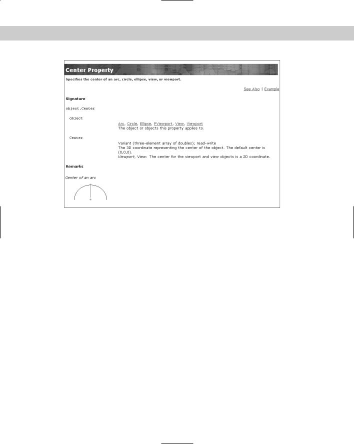
Figure 37-4: The help page for the Center Property.
For more general help, AutoCAD offers two systems:
The ActiveX and VBA Reference is an alphabetical listing of objects, methods, properties, and events.
The ActiveX and VBA Developer’s Guide explains ActiveX automation concepts and techniques.
To access these reference guides, switch to AutoCAD and choose Help Developer Help.
The Microsoft Visual Basic for Applications Help provides information on the general VBA environment. Click Help on the VBA IDE Menu Bar toolbar or choose Help Microsoft Visual Basic Help. Here you see help for other VBA-enabled applications you may have. Use this when you’re ready to write VBA code that integrates more than one application.
After you start programming, you can get help on any expression by placing the cursor in it and pressing F1. For example, you can type AddLine and press F1 to get help on how to create a line.
Writing VBA Code
Now that you’re familiar with the structure of VBA objects, methods, and properties, you’re ready to start writing some code. As with any programming language, you need to learn syntax and understand variables and when to use them. Luckily, AutoCAD’s VBA Help includes many examples to guide you along the way. After you write some code, you can use it in AutoCAD.
1054 Part VII Programming AutoCAD
Table 37-1 lists the various components of VBA code. This table defines various terms that you can often use when working with VBA.
|
Table 37-1: Components of VBA Code |
|
|
Term |
Definition |
|
|
Procedure |
Code that does something and has a name. A procedure can be a subroutine, a |
|
function, or a property. |
Project |
A set of forms and modules. |
Module |
A set of subroutines, functions, and declarations that are usually related and |
|
comprise a distinct component in a project. A module can contain zero (0) or |
|
more procedures (subroutines and functions). |
Form |
A container for the visual components, such as buttons and text boxes, of a dialog |
|
box that you create for your VBA project. |
Subroutine |
A procedure, written in VBA code, that does not return a value. |
Function |
A procedure, written in VBA code, that returns a value. |
Property |
A procedure, written in VBA code that specifies a value (the property of an object). |
Declaration |
One or more nonexecutable statements that name constants or variables and |
|
define their attributes (such as data type). |
Macro |
A public subroutine that a user can directly execute. |
|
|
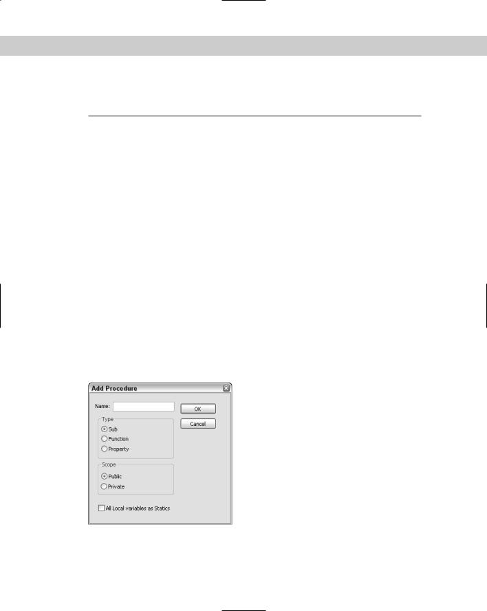
When you start to create code, VBA can create the basic structure for each procedure for you. Choose Insert Procedure (the Object Browser must be closed) to open the Add Procedure dialog box shown in Figure 37-5.
Figure 37-5: The Add Procedure dialog box.
In the Name text box, type in a name for the new procedure, and then choose the type of procedure you want to create. Choose whether you want the scope to be Public or Private and

Chapter 37 Programming with Visual Basic for Applications 1055
then click OK. If a subroutine (called sub for short) is declared Public, it is visible (can be called) from other modules or from the AutoCAD vbarun dialog box. A sub that is declared Private is only visible within that module.
Note If you check All Local Variables as Statics in the Add Procedure dialog box, your variables retain their values between the times they’re used.
Looking at VBA syntax
To start programming, you need an idea of how a VBA routine is put together. Here is a complete VBA routine that draws a 3D box.
‘Insert a 3D Solid Box |
|
||
Sub Box() |
|
|
|
‘declare |
input variables to AddBox() |
||
Dim |
dOrigin(0 To 2) As Double ‘origin is array of doubles |
||
‘(x,y,z) |
|
|
|
Dim |
dLength |
As Double |
‘length |
Dim |
dWidth As Double |
‘width |
|
Dim |
dHeight |
As Double |
‘height |
Dim |
myBox As Acad3DSolid |
‘holds return from AddBox() |
|
dOrigin(0) = 0# |
‘set origin to (0,0,0) |
||
dOrigin(1) = 0# |
|
||
dOrigin(2) = 0# |
|
||
dLength = 5# |
|
‘make a cube 5 by 5 by 5 |
|
dWidth = 5# |
|
|
|
dHeight = 5# |
|
||
‘create the |
box in modelspace of the current drawing |
||
Set |
myBox = |
ThisDrawing.ModelSpace.AddBox(dOrigin, dLength, |
|
dWidth, dHeight) |
|
|
|
‘change the |
viewpoint to better see the box |
||
ThisDrawing.SendCommand (“VPOINT 1,1,1 “)
End Sub
Here’s what the code means:
Line 1: Any text starting with an apostrophe (‘) is a comment. Placing comments in your routines helps you and others understand what you’re doing.
Line 2: Sub indicates the start of a procedure — a named, unified piece of code. You can have several subroutines in a VBA project. A project is the file you save, and it has a DVB filename extension. Each project contains the components of your subroutines, dialog boxes, and so on. The next word is the name of the subroutine. Within the parentheses, you can add arguments, if any. Use an empty set of parentheses if there are no arguments. Declaring variables is discussed later in this chapter.
Line 3: Another comment describing the next few lines of code. It’s always a good idea to comment your code, indicate what is happening, and even write notes to yourself to remind you of your intent.

1056 Part VII Programming AutoCAD
Line 4: You can also declare variables using the Dim statement. Here dOrigin is used as the variable for the center of the box. (0 To 2) means that the origin will have three parts to it, for the X, Y, and Z coordinates. Double is a type of variable suitable for most coordinates. More about variable types later.
Lines 5–7: Here you declare the dLength, dWidth, and dHeight variables, which will be used as the length, width, and height of the box. These are declared as type Double, which is also indicated by the d prefix on the variable names. This isn’t required, but it’s a good idea to use a naming scheme for variables to help remind you of its type, especially as you get deeper into programming or have to come back to some code after not seeing it for a while.
Line 8: Here you declare a variable called myBox as an Acad3DSolid to refer to the new box that will be created. Acad3DSolid is a data type specific to AutoCAD, suitable for (you guessed it) referencing a 3D solid in your drawing. You can find other AutoCAD data types by looking in the Object Browser or looking at the Object Model as explained earlier in this chapter.
Lines 9–11: Here you specify the X, Y, and Z coordinates of the origin of the box. The values are assigned to the dOrigin variable. The pound sign (#) is used to indicate a double-precision floating-point value. Use of the # sign is not required here but is more accurate and more clearly indicates your intentions. In some situations rounding errors can occur when assigning numbers of one type to variables of another type, such as assigning integers to doubles and doubles to integers.
Lines 12–14: Set the length, width, and height of the box to 5.
Line 15: Another comment.
Line 16: Finally, you’re ready to actually do something. The Set statement is used to set a variable to an object. Here you set the variable myBox to an Acad3DSolid defined by AddBox(dOrigin, dLength, dWidth, dHeight). The AddBox method creates a new 3D Box. You need to define its origin, length, width, and height by using the variables you’ve previously defined. The AddBox method is a member of ModelSpace, which is a member of ThisDrawing. You use ThisDrawing in VBA to access the current drawing. Because VBA within AutoCAD is automatically connected to AutoCAD, you don’t need to specify the application (that is, AutoCAD).
Line 17: Not another comment! Ask yourself these questions: If I looked at this code without the comments, would I have a harder time understanding it? What if there is a bug and I ask another programmer to find it? What if I am that programmer?
Line 18: Here we send the VPOINT command to change the viewpoint. Otherwise the box we just created will simply look like a square viewed from the top. The space after the numbers 1,1,1 and before the quotation mark is important. It signifies the end of the command. It’s like pressing the Enter key for this command.
Line 19: End Sub ends the subroutine.
To find the syntax for a statement you want to use, look in VBA Help, as explained in the “Getting help” section earlier in this chapter. In the preceding VBA routine, you might want to click AddBox and press F1 to find the syntax and elements required for creating a box. Then click Example to see an actual example of code for that statement.

Chapter 37 Programming with Visual Basic for Applications 1057
Saving a VBA routine
As I mention earlier, the AutoCAD version of VBA saves VBA projects as separate files with a DVB filename extension. However, when you run a routine, AutoCAD lists it in the format
ModuleName:Procedure Name. If your project has only one module, you can give the module and the procedure the same name. However, most VBA routines have more than one module, with one module controlling the rest. By running the controlling module, you run the whole project.
To name a module, look in the Properties window. After you’ve created a module, the VBA IDE lists its name property as Module1 by default. Double-click Module1 and type a new name. Notice that the module name in the Project window also changes accordingly.
Note A module name (as well as the names of other forms and controls) must start with a letter and can be up to 40 characters. Only letters, numbers, and the underscore character are allowed.
To save a project as a separate file, which includes all the modules, click Save on the VBA IDE Standard toolbar. VBA returns you to AutoCAD and opens the Save As dialog
box. Type a name for your project, choose a location, and click Save.
You can save your project in the Sample\VBA subfolder in the AutoCAD 2005 folder or use another folder that is in AutoCAD’s support-file search path.
Loading a VBA routine
Before running a VBA routine, it must be loaded. If you’re working on the routine and want to run it to check how it works — which you’ll do often — you don’t need to load the routine.
However, if you want to run a routine that hasn’t been opened, you need to use the VBALOAD command. Choose Tools Macro Load Project (or type vbaload ) and AutoCAD opens the Open VBA Project dialog box. Navigate to your project, choose it, and click Open. (AutoCAD asks you to confirm that you want to enable macros.) The project is now loaded.
Running a VBA routine
After you complete a subroutine, you can run it in AutoCAD. After all, that’s the reason for writing VBA code in the first place. To run a VBA routine, choose Tools Macro Macros (or type vbarun ). In the Macros dialog box, choose the module you want to run and click Run. AutoCAD runs the module, including other modules that may be controlled by the module you run.
Using the Visual Basic Editor
When you type code from scratch in the Visual Basic Editor, you immediately notice that Visual Basic color-codes your text as you go. The most common colors are:
Normal text |
Black |
Syntax error text |
Red |
Comments |
Green |
Keyword text |
Blue |

1058 Part VII Programming AutoCAD
|
Keywords include variable types and other words that Visual Basic knows, such as Dim |
|
and Sub. |
Tip |
You can customize these colors by choosing Tools Options from the Visual Basic menu and |
|
then choosing the Editor Format tab. Choose a type of text and then choose the desired |
|
color. Click OK. |
|
When you start to type a keyword that Visual Basic knows, you’ll often see a box pop up that |
|
enables you to choose from a list or helps you complete the word. The editor also adds or |
|
removes spaces and capitalizes certain words for you to improve your syntax. If you make a |
|
syntax mistake, a small error message often appears as you work. In these ways, the Visual |
|
Basic Editor helps you type accurate code. |
STEP-BY-STEP: Creating, Saving, and Running a VBA Program
1.Open a new drawing using the acad.dwt template. Choose Tools Macro Visual Basic Editor.
2.Choose Insert Module. VBA opens the module text editor. (If you’ve previously opened a module, Visual Basic may open with a blank module already open. In that case, skip this step.)
3.Choose Insert Procedure. In the Name text box, type DrawTorus. The type should be Sub and the scope should be public. Click OK.
4.Type the following code. (Note that the second and last lines are already there for you.)
‘insert a Torus
Public Sub DrawTorus() ‘declare variables
Dim dCenter(0 To 2) As Double Dim dRadius1 As Double
Dim dRadius2 As Double
Dim myTorus As Acad3DSolid
‘set center of torus to 0,0,0 dCenter(0) = 0#
dCenter(1) = 0# dCenter(2) = 0#
dRadius1 |
= |
10# |
‘ |
torus radius |
dRadius2 |
= |
2# |
‘ |
tube radius |
‘insert the torus
Set myTorus = ThisDrawing.ModelSpace.AddTorus(dCenter, dRadius1, dRadius2)
‘set the viewpoint and shade it
ThisDrawing.SendCommand (“VPOINT 1,1,1 SHADEMODE GOURAUD “) End Sub
5. In the Properties window, change the name of the module to DrawTorus.

Chapter 37 Programming with Visual Basic for Applications 1059
6.Because this routine is active, you don’t need to load it. Choose Save on the VBA IDE Standard toolbar. Save the project as ab37-01.dvb in your AutoCAD Bible folder.
7.Use the Windows task bar to return to your drawing. Choose Tools Macro Macros. In the Macro dialog box, choose DrawTorus and click Run. VBA draws and shades the torus.
Don’t save your drawing.
Here’s an explanation of the routine you just wrote and used. Note that blank lines are ignored.
Line 1: This is a public subroutine named DrawTorus with no parameters.
Line 2: Comment describing routine.
Line 3: Comment indicating which variable declarations are next.
Line 4: Declare the array to hold the X, Y, and Z coordinates for the center of the torus.
Line 5: Declare the variable to hold the radius of the torus.
Line 6: Declare the variable to hold the radius of the tube.
Line 7: Declare the variable to hold the created 3D object.
Line 8: Comment.
Lines 9–11: Set the center to 0,0,0.
Line 12: Set the torus radius to 10.0.
Line 13: Set the tube radius to 2.0.
Line 14: Comment.
Line 15: Create the torus.
Line 16: Comment.
Line 17: Send commands to AutoCAD to set the viewpoint and shade the torus for better viewing.
Line 18: End of subroutine.
Understanding variables
A variable holds a value for later use in your program. In VBA, you don’t need to explicitly declare your variables in advance (as long as you don’t include Option Explicit, explained later). You can use the Set statement to set a variable to an object, as in the example here. This statement creates a variable, cir, and sets its value equal to the circle that the AddCircle method creates.
Set cir = ThisDrawing.ModelSpace.AddCircle(cen, radius)
When you create a variable in this way, VBA assigns the default variant type to it. The variant type of variable can contain numbers, dates, or strings (of text).
1060 Part VII Programming AutoCAD
However, declaring variables explicitly in advance has two advantages:
You can specify the type of variable, which usually uses less memory than the default variant type.
As you continue to enter code, VBA checks the variable’s spelling for you, reducing the chance for errors.
You declare variables using the Dim statement. Here’s an example:
Dim radius As Double
You can create three different levels of variables:
A public variable is available to all procedures in the project. It is shown as follows:
Public dRadius As Double
A module-level variable is available to all the procedures in the module. You create a module-level variable by placing the declaration (with the Dim statement) at the top of a module, in a Declarations section. Another way to create a module-level variable is to use the Private statement. Examples are shown here:
Dim dNum3 as Double Private dNum2 as Double
A procedure-level variable is used only within a procedure. You can place the variable anywhere within the procedure as long as you declare the variable before you use it.
Placing the statement Option Explicit in a Declarations section requires all variables to be declared. Using Option Explicit is a way to force yourself to write your code more carefully. Declared variables are easier to debug because they’re easier to find.
Table 37-2 describes the kinds of variables you can declare.
|
Table 37-2: VBA Variable Types |
|
|
Variable |
Description |
|
|
Boolean |
For variables that can have only two values — True or False. |
Byte |
Positive integers from 0 to 255. |
Integer |
Integers from –32,768 to +32,768. |
Long |
Integers from –2,147,483,648 to +2,147,483,648. |
Currency |
Values from –922,337,203,685,477.5808 to +922,337,203,685,477.5808. Use this |
|
variable for currency or for other values that need accuracy to several decimals. |
Single |
Single-precision floating-point values. Single variables use less memory than double |
|
variables, but their values are limited. |
Double |
Double-precision floating-point values. Double variables offer much greater |
|
precision than single variables. Most coordinates use this variable type. Three |
|
double variables create the X, Y, and Z values. |
Date |
Holds dates and times stored as real numbers. The number to the left of the |
|
decimal is the date and the number to the right of the decimal is the time. |

Chapter 37 Programming with Visual Basic for Applications 1061
Variable |
Description |
|
|
String |
Fixed or variable-length text strings, including letters, numbers, spaces, and |
|
punctuation characters. |
Object |
Objects such as an application, a drawing, or a drawing object. |
Variant |
Contains numbers, dates, or strings. When you don’t declare a type for a variable, |
|
VBA uses this type by default. |
|
|
Here’s an example that uses the date variable type and displays it in a message box:
Sub DateDemo() |
|
|
|
Dim dt As Date |
|
|
|
Dim dbl |
As Double |
|
|
dt = Now |
‘ set the dt to the current |
date and time |
|
dbl |
= dt |
‘ assign this date value to |
a double |
MsgBox “Normal date version: “ & dt & “ Double |
version: “ & dbl |
||
End Sub |
|
|
|
Running DateDemo (by pressing F5) would show something similar to:
Normal date version: 1/25/2003 10:16:27 AM
Double version: 37646.4280902778
Creating VBA statements
Although a complete discussion of how to write VBA code is beyond the scope of this book, some general principles will be helpful.
A statement in VBA is the most basic unit of code. It contains a complete instruction. There are three kinds of statements:
A declaration names a variable, constant, or procedure, as in this example:
Dim dOrigin as Double
An assignment assigns a value to a variable or constant. For example: dOrigin = 0#
An executable creates an action. For example, it can execute a method or function or create a loop or branch that acts on a block of code, as shown here:
Set myBox = ThisDrawing.ModelSpace.AddBox(dOrigin, dLength, dWidth, dHeight)
VBA has many keywords and functions and other components you use to create code. To find the basic components of the VBA language, choose Help Microsoft Visual Basic Help. From the Contents tab, double-click Visual Basic Language Reference, which lists terms that are part and parcel of VBA. Here are some examples:
Constants: Constants can be used anywhere in your code to provide a named value. For example, VBA offers color and date constants you can use to specify colors and dates.
Functions: VBA includes many functions you’ll find familiar if you’ve used AutoLISP. For example, the ABS function returns the absolute value (without a plus or minus sign) of any number. The DATE function returns the current system date.