

- •Foreword
- •Preface
- •Is This Book for You?
- •How This Book Is Organized
- •How to Use This Book
- •Doing the Exercises
- •Conventions Used in This Book
- •What the Icons Mean
- •About the CD-ROM
- •Other Information
- •Contacting the Author
- •Acknowledgments
- •Contents at a Glance
- •Contents
- •Getting Acquainted with AutoCAD and AutoCAD LT
- •Starting AutoCAD and AutoCAD LT
- •Creating a New Drawing
- •Using the AutoCAD and AutoCAD LT Interface
- •Creating Your First Drawing
- •Saving a Drawing
- •Summary
- •Creating a New Drawing from a Template
- •Working with Templates
- •Opening a Drawing with Default Settings
- •Opening an Existing Drawing
- •Using an Existing Drawing as a Prototype
- •Saving a Drawing Under a New Name
- •Summary
- •The Command Line
- •Command Techniques
- •Of Mice and Pucks
- •Getting Help
- •Summary
- •Typing Coordinates
- •Displaying Coordinates
- •Picking Coordinates on the Screen
- •Locating Points
- •Summary
- •Unit Types
- •Drawing Limits
- •Understanding Scales
- •Inserting a Title Block
- •Common Setup Options
- •The MVSETUP Command
- •Summary
- •Using the LINE Command
- •Drawing Rectangles
- •Drawing Polygons
- •Creating Construction Lines
- •Creating Rays
- •Summary
- •Drawing Circles
- •Drawing Arcs
- •Creating Ellipses and Elliptical Arcs
- •Making Donuts
- •Placing Points
- •Summary
- •Panning
- •The ZOOM Command
- •Aerial View
- •Named Views
- •Tiled Viewports
- •Snap Rotation
- •User Coordinate Systems
- •Isometric Drawing
- •Summary
- •Editing a Drawing
- •Selecting Objects
- •Summary
- •Copying and Moving Objects
- •Using Construction Commands
- •Creating a Revision Cloud
- •Hiding Objects with a Wipeout
- •Double-Clicking to Edit Objects
- •Grips
- •Editing with the Properties Palette
- •Selection Filters
- •Groups
- •Summary
- •Working with Layers
- •Changing Object Color, Linetype, and Lineweight
- •Working with Linetype Scales
- •Importing Layers and Linetypes from Other Drawings
- •Matching Properties
- •Summary
- •Drawing-Level Information
- •Object-Level Information
- •Measurement Commands
- •AutoCAD’s Calculator
- •Summary
- •Creating Single-Line Text
- •Understanding Text Styles
- •Creating Multiline Text
- •Creating Tables
- •Inserting Fields
- •Managing Text
- •Finding Text in Your Drawing
- •Checking Your Spelling
- •Summary
- •Working with Dimensions
- •Drawing Linear Dimensions
- •Drawing Aligned Dimensions
- •Creating Baseline and Continued Dimensions
- •Dimensioning Arcs and Circles
- •Dimensioning Angles
- •Creating Ordinate Dimensions
- •Drawing Leaders
- •Using Quick Dimension
- •Editing Dimensions
- •Summary
- •Understanding Dimension Styles
- •Defining a New Dimension Style
- •Changing Dimension Styles
- •Creating Geometric Tolerances
- •Summary
- •Creating and Editing Polylines
- •Drawing and Editing Splines
- •Creating Regions
- •Creating Boundaries
- •Creating Hatches
- •Creating and Editing Multilines
- •Creating Dlines
- •Using the SKETCH Command
- •Digitizing Drawings with the TABLET Command
- •Summary
- •Preparing a Drawing for Plotting or Printing
- •Creating a Layout in Paper Space
- •Working with Plot Styles
- •Plotting a Drawing
- •Summary
- •Combining Objects into Blocks
- •Inserting Blocks and Files into Drawings
- •Managing Blocks
- •Using Windows Features
- •Working with Attributes
- •Summary
- •Understanding External References
- •Editing an Xref within Your Drawing
- •Controlling Xref Display
- •Managing Xrefs
- •Summary
- •Preparing for Database Connectivity
- •Connecting to Your Database
- •Linking Data to Drawing Objects
- •Creating Labels
- •Querying with the Query Editor
- •Working with Query Files
- •Summary
- •Working with 3D Coordinates
- •Using Elevation and Thickness
- •Working with the User Coordinate System
- •Summary
- •Working with the Standard Viewpoints
- •Using DDVPOINT
- •Working with the Tripod and Compass
- •Getting a Quick Plan View
- •Shading Your Drawing
- •Using 3D Orbit
- •Using Tiled Viewports
- •Defining a Perspective View
- •Laying Out 3D Drawings
- •Summary
- •Drawing Surfaces with 3DFACE
- •Drawing Surfaces with PFACE
- •Creating Polygon Meshes with 3DMESH
- •Drawing Standard 3D Shapes
- •Drawing a Revolved Surface
- •Drawing an Extruded Surface
- •Drawing Ruled Surfaces
- •Drawing Edge Surfaces
- •Summary
- •Drawing Standard Shapes
- •Creating Extruded Solids
- •Drawing Revolved Solids
- •Creating Complex Solids
- •Sectioning and Slicing Solids
- •Using Editing Commands in 3D
- •Editing Solids
- •Listing Solid Properties
- •Summary
- •Understanding Rendering
- •Creating Lights
- •Creating Scenes
- •Working with Materials
- •Using Backgrounds
- •Doing the Final Render
- •Summary
- •Accessing Drawing Components with the DesignCenter
- •Accessing Drawing Content with Tool Palettes
- •Setting Standards for Drawings
- •Organizing Your Drawings
- •Working with Sheet Sets
- •Maintaining Security
- •Keeping Track of Referenced Files
- •Handling Errors and Crashes
- •Managing Drawings from Prior Releases
- •Summary
- •Importing and Exporting Other File Formats
- •Working with Raster Images
- •Pasting, Linking, and Embedding Objects
- •Summary
- •Sending Drawings
- •Opening Drawings from the Web
- •Creating Object Hyperlinks
- •Publishing Drawings
- •Summary
- •Working with Customizable Files
- •Creating Keyboard Shortcuts for Commands
- •Customizing Toolbars
- •Customizing Tool Palettes
- •Summary
- •Creating Macros with Script Files
- •Creating Slide Shows
- •Creating Slide Libraries
- •Summary
- •Creating Linetypes
- •Creating Hatch Patterns
- •Summary
- •Creating Shapes
- •Creating Fonts
- •Summary
- •Working with Menu Files
- •Customizing a Menu
- •Summary
- •Introducing Visual LISP
- •Getting Help in Visual LISP
- •Working with AutoLISP Expressions
- •Using AutoLISP on the Command Line
- •Creating AutoLISP Files
- •Summary
- •Creating Variables
- •Working with AutoCAD Commands
- •Working with Lists
- •Setting Conditions
- •Managing Drawing Objects
- •Getting Input from the User
- •Putting on the Finishing Touches
- •Summary
- •Understanding Local and Global Variables
- •Working with Visual LISP ActiveX Functions
- •Debugging Code
- •Summary
- •Starting to Work with VBA
- •Writing VBA Code
- •Getting User Input
- •Creating Dialog Boxes
- •Modifying Objects
- •Debugging and Trapping Errors
- •Moving to Advanced Programming
- •A Final Word
- •Installing AutoCAD and AutoCAD LT
- •Configuring AutoCAD
- •Starting AutoCAD Your Way
- •Configuring a Plotter
- •System Requirements
- •Using the CD with Microsoft Windows
- •What’s on the CD
- •Troubleshooting
- •Index

Chapter 17 Plotting and Printing Your Drawing |
479 |
9.In the description box of the General tab, type AutoCAD Bible Plot Style Table.
10.Click the Table View tab. Click the name Style1. Type Black color and press Enter.
11.Click the Color row under the Black Color column and choose Black from the drop-down list. Click Save & Close. Close the Plot Styles folder window.
12.Click Layout1. In the Page Setup Manager, choose Modify. In the Page Setup dialog box, choose ab17-3.stb from the Plot Style Table drop-down list. Check the Display Plot Styles check box and click OK. Click Close. This assigns the plot-style table to Layout1.
13.Choose Layer Properties Manager from the Layers toolbar. In the Layer Properties Manager, choose A-DETL-PATT (the layer with the magenta color). Click that layer’s Plot Styles column to open the Select Plot Style dialog box. Choose Black Color and click OK. The Plot Style for the A-DETL-PATT layer now shows as Black Color. Click OK to close the Layer Properties Manager.
14.Type regenall . The objects on A-DETL-PATT (the diagonal marks on the mirror) now show as black and will plot as black.
15.Click Properties on the Standard toolbar to open the Properties palette.
16.Click PAPER on the status bar to switch to model space.
17.Select the bottom horizontal line of the sink cabinet.
18.In the Properties palette, click Plot Style. From the drop-down list to the right, choose Black Color.
19.Press Esc so that the object is no longer highlighted. The line appears as black.
20.Choose Tools Options. On the Plot and Publish tab, change the Default Plot Style Behavior for New Drawings setting to what it was at the beginning of this exercise.
21.Save your drawing.
On the |
The plot style you created, ab17-3.stb, is in the Results folder on the CD-ROM. |
CD-ROM |
|
Plotting a Drawing
After you lay out your drawing, you’re ready to plot it. Plotting outputs your drawing onto paper (or perhaps vellum or some other medium). Although you might go through several iterations of drawing and editing in electronic form, you eventually plot most drawings. The first step is to check the plotter or printer — it should be on, connected to your computer, and have the appropriate paper in it. Your drawing should appear on the screen.
Cross- |
For more information on configuring plotters, see Appendix A. For information on plotting |
Reference |
electronically to a DWF file and on plotting drawing sets, see Chapter 26. |
|
480 Part II Drawing in Two Dimensions
Configuring your plotter
Most printers and plotters have many settings that you can control from within AutoCAD or AutoCAD LT. You can also control how information about the drawing is sent to the printer or plotter. The settings that configure how your plotter functions are in the Plotter Configuration Editor, shown here.
To configure your plotter, choose File Plotter Manager to open a window for the \Plotters folder. (To find the location of the Plotters folder, choose Tools Options and click the Files tab. Double-click Printer Support File Path. Then double-click Printer Configuration Search Path to display the location.)
Plotter configuration settings are stored in PC3 files. Double-click the PC3 file icon for the plotter you want to configure to open the Plotter Configuration Editor. (You can also open the Plotter Configuration Editor from the Plot dialog box — click Properties in the Printer/Plotter section.) Click the Device and Document Settings tab. The top section lists the possible types of settings. To open a list with a plus sign to its left, click the plus sign; suboptions appear. As you click each item on the top, the appropriate settings appear in the lower section. For example, if you want to set the color, speed, and width for each pen in a pen plotter, click physical pen characteristics. Then, in the bottom half of the Editor, you can click each pen in the carousel and change its characteristics. Choose Custom Paper Sizes to add custom sheet sizes; these will then appear in the Page Setup and Plot dialog boxes so you can choose them when you plot. In each case, the Editor walks you through the choices you need to make to configure your plotter. See Appendix A for further information.

Chapter 17 Plotting and Printing Your Drawing |
481 |
You can filter out unused paper sizes using the Plotter Configuration Editor. However, at the end of the process, you can opt to apply the change only to the current plot. Follow these steps:
New
Feature
1.On the Device and Document Settings tab, choose Filter Paper Sizes.
2.In the list of paper sizes, uncheck sizes you don’t want to display.
3.Click OK.
4.In the Changes to a Printer Configuration File dialog box, choose to apply the changes only to the current plot or to the file (that is, permanently or until you edit the printer configuration file again).
5.Click OK.
To start plotting, choose Plot from the Standard toolbar to open the Plot dialog box, shown in Figure 17-17. As you can see, this dialog box is almost identical to the Page
Setup dialog box.
You can hide the right side of the Plot dialog box if you don’t need the features there. Click the arrow at the lower-right corner of the dialog box.
If you set the Layout Settings in the Page Setup dialog box and set them current, those settings were saved with the tab that was current at the time. You can usually just click OK in the Plot dialog box and plot immediately. Plot settings are saved in your drawing.
If you saved a page setup, you can choose it from the drop-down list in the Page Setup section of the dialog box. See the discussion of the Page Setup dialog box earlier in this chapter for details on the settings in this dialog box.
Figure 17-17: The Plot dialog box.

482 Part II Drawing in Two Dimensions
|
Choosing a plotter/printer |
|
To select a plotter or printer, choose one from the drop-down list in the Printer/Plotter section |
|
of the dialog box. A plotter must be either a Windows system printer or a configured plotter. |
|
To add a system printer, choose Start Settings Printers and double-click Add a Printer. To |
|
add a configured plotter, which has a driver especially to optimize the functioning of that plot- |
|
ter, use the Add Plotter Wizard. (Choose Tools Wizards Add Plotter.) |
Tip |
To avoid inadvertently plotting to a Windows system printer when you should be plotting to a |
|
plotter, you can hide the display of Windows system printers in the Plot and Page Setup dia- |
|
log boxes. Because these printers won’t appear on the list of plotters, you can’t plot to them. |
|
To hide system printers, choose Tools Options and click the Plot and Publish tab. In the |
|
General Plot Options section of the dialog box, check Hide System Printers and click OK. |
|
If you want to use a plot-style table, check that it appears in the Plot Style Table drop-down list. |
|
To choose how many copies you want to plot, change the number in the Number of Copies |
|
text box. |
|
Check the Plot to File check box to create a plot file rather than a paper plot. When you click |
|
OK, the Browse for Plot File dialog box opens so that you can choose a name and location. |
|
Click Save to create the plot file. |
|
You can merge overlapping objects so that the same area is not printed more than once. To |
|
set the Merge Overlapping property: |
1.Click Properties in the Printer/Plotter section of the Plot dialog box.
2.In the Plotter Configuration Editor that opens, display the Device and Document Settings tab. Click the plus sign (+) next to Graphics. If you see Merge Control in the Graphics list that opens, you can use this feature on your printer or plotter. (For more information about the Plotter Configuration Editor, see the sidebar “Configuring your plotter.”)
3.Click Merge Control. In the Merge Control area that is displayed, choose either Lines Overwrite or Lines Merge and click OK.
4.You then have the choice of applying the change to the current plot only or making the change permanent by editing the PC3 file that contains the parameters for your plotter or printer. Choose one of the options and click OK.
Previewing your plot
You should preview your drawing before you plot. Choose Preview to see exactly how your drawing will plot. The Print Preview button on the Standard toolbar is just like the one you have in your Windows word processor. When you choose Print Preview, you see a preview of your plot using current plot parameters. Right-click to open the shortcut menu that lets you plot, zoom, pan, or exit the preview.
Tip I cover previewing a plot last because it should be the last step before you actually plot. However, it can also be the first step, helping you to determine what settings you need.
Chapter 17 Plotting and Printing Your Drawing |
483 |
|
Creating the plot |
|
To start the plotting process, simply click OK in the Plot dialog box. |
New |
You can now plot in the background, which means that you can continue to work while your |
Feature |
drawing is plotting. By default, background plotting is off. To turn it on, choose Tools Options |
|
|
|
and click the Plot and Publish tab. In the Background Processing Options section, check the |
|
Plotting check box. You can also separately specify background plotting for publishing, which |
|
I cover in Chapter 26. (Background plotting is on by default for publishing.) |
If you’re plotting in the background, you can place your cursor over the plotter icon in the status tray to view information about the status of the plot.
When the plot is finished, a new notification bubble appears at the lower-left corner of your screen, as shown in Figure 17-18. As you can see, you can click the link to view the Plot and Publish Details.
Figure 17-18: This bubble appears when your plot is done.
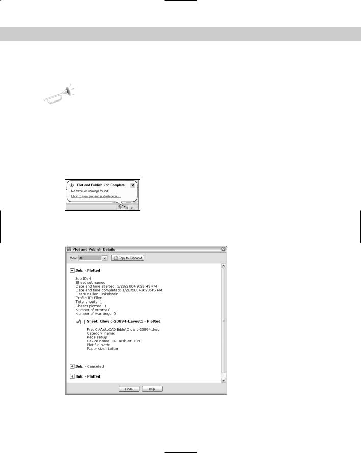
If you view the Plot and Publish Details, you get a report like the one shown in Figure 17-19. You can see details for all plots that you did in the current session of AutoCAD or AutoCAD LT.
Figure 17-19: The Plot and Publish Details report tells you what happened when you plotted your drawings.