

- •Foreword
- •Preface
- •Is This Book for You?
- •How This Book Is Organized
- •How to Use This Book
- •Doing the Exercises
- •Conventions Used in This Book
- •What the Icons Mean
- •About the CD-ROM
- •Other Information
- •Contacting the Author
- •Acknowledgments
- •Contents at a Glance
- •Contents
- •Getting Acquainted with AutoCAD and AutoCAD LT
- •Starting AutoCAD and AutoCAD LT
- •Creating a New Drawing
- •Using the AutoCAD and AutoCAD LT Interface
- •Creating Your First Drawing
- •Saving a Drawing
- •Summary
- •Creating a New Drawing from a Template
- •Working with Templates
- •Opening a Drawing with Default Settings
- •Opening an Existing Drawing
- •Using an Existing Drawing as a Prototype
- •Saving a Drawing Under a New Name
- •Summary
- •The Command Line
- •Command Techniques
- •Of Mice and Pucks
- •Getting Help
- •Summary
- •Typing Coordinates
- •Displaying Coordinates
- •Picking Coordinates on the Screen
- •Locating Points
- •Summary
- •Unit Types
- •Drawing Limits
- •Understanding Scales
- •Inserting a Title Block
- •Common Setup Options
- •The MVSETUP Command
- •Summary
- •Using the LINE Command
- •Drawing Rectangles
- •Drawing Polygons
- •Creating Construction Lines
- •Creating Rays
- •Summary
- •Drawing Circles
- •Drawing Arcs
- •Creating Ellipses and Elliptical Arcs
- •Making Donuts
- •Placing Points
- •Summary
- •Panning
- •The ZOOM Command
- •Aerial View
- •Named Views
- •Tiled Viewports
- •Snap Rotation
- •User Coordinate Systems
- •Isometric Drawing
- •Summary
- •Editing a Drawing
- •Selecting Objects
- •Summary
- •Copying and Moving Objects
- •Using Construction Commands
- •Creating a Revision Cloud
- •Hiding Objects with a Wipeout
- •Double-Clicking to Edit Objects
- •Grips
- •Editing with the Properties Palette
- •Selection Filters
- •Groups
- •Summary
- •Working with Layers
- •Changing Object Color, Linetype, and Lineweight
- •Working with Linetype Scales
- •Importing Layers and Linetypes from Other Drawings
- •Matching Properties
- •Summary
- •Drawing-Level Information
- •Object-Level Information
- •Measurement Commands
- •AutoCAD’s Calculator
- •Summary
- •Creating Single-Line Text
- •Understanding Text Styles
- •Creating Multiline Text
- •Creating Tables
- •Inserting Fields
- •Managing Text
- •Finding Text in Your Drawing
- •Checking Your Spelling
- •Summary
- •Working with Dimensions
- •Drawing Linear Dimensions
- •Drawing Aligned Dimensions
- •Creating Baseline and Continued Dimensions
- •Dimensioning Arcs and Circles
- •Dimensioning Angles
- •Creating Ordinate Dimensions
- •Drawing Leaders
- •Using Quick Dimension
- •Editing Dimensions
- •Summary
- •Understanding Dimension Styles
- •Defining a New Dimension Style
- •Changing Dimension Styles
- •Creating Geometric Tolerances
- •Summary
- •Creating and Editing Polylines
- •Drawing and Editing Splines
- •Creating Regions
- •Creating Boundaries
- •Creating Hatches
- •Creating and Editing Multilines
- •Creating Dlines
- •Using the SKETCH Command
- •Digitizing Drawings with the TABLET Command
- •Summary
- •Preparing a Drawing for Plotting or Printing
- •Creating a Layout in Paper Space
- •Working with Plot Styles
- •Plotting a Drawing
- •Summary
- •Combining Objects into Blocks
- •Inserting Blocks and Files into Drawings
- •Managing Blocks
- •Using Windows Features
- •Working with Attributes
- •Summary
- •Understanding External References
- •Editing an Xref within Your Drawing
- •Controlling Xref Display
- •Managing Xrefs
- •Summary
- •Preparing for Database Connectivity
- •Connecting to Your Database
- •Linking Data to Drawing Objects
- •Creating Labels
- •Querying with the Query Editor
- •Working with Query Files
- •Summary
- •Working with 3D Coordinates
- •Using Elevation and Thickness
- •Working with the User Coordinate System
- •Summary
- •Working with the Standard Viewpoints
- •Using DDVPOINT
- •Working with the Tripod and Compass
- •Getting a Quick Plan View
- •Shading Your Drawing
- •Using 3D Orbit
- •Using Tiled Viewports
- •Defining a Perspective View
- •Laying Out 3D Drawings
- •Summary
- •Drawing Surfaces with 3DFACE
- •Drawing Surfaces with PFACE
- •Creating Polygon Meshes with 3DMESH
- •Drawing Standard 3D Shapes
- •Drawing a Revolved Surface
- •Drawing an Extruded Surface
- •Drawing Ruled Surfaces
- •Drawing Edge Surfaces
- •Summary
- •Drawing Standard Shapes
- •Creating Extruded Solids
- •Drawing Revolved Solids
- •Creating Complex Solids
- •Sectioning and Slicing Solids
- •Using Editing Commands in 3D
- •Editing Solids
- •Listing Solid Properties
- •Summary
- •Understanding Rendering
- •Creating Lights
- •Creating Scenes
- •Working with Materials
- •Using Backgrounds
- •Doing the Final Render
- •Summary
- •Accessing Drawing Components with the DesignCenter
- •Accessing Drawing Content with Tool Palettes
- •Setting Standards for Drawings
- •Organizing Your Drawings
- •Working with Sheet Sets
- •Maintaining Security
- •Keeping Track of Referenced Files
- •Handling Errors and Crashes
- •Managing Drawings from Prior Releases
- •Summary
- •Importing and Exporting Other File Formats
- •Working with Raster Images
- •Pasting, Linking, and Embedding Objects
- •Summary
- •Sending Drawings
- •Opening Drawings from the Web
- •Creating Object Hyperlinks
- •Publishing Drawings
- •Summary
- •Working with Customizable Files
- •Creating Keyboard Shortcuts for Commands
- •Customizing Toolbars
- •Customizing Tool Palettes
- •Summary
- •Creating Macros with Script Files
- •Creating Slide Shows
- •Creating Slide Libraries
- •Summary
- •Creating Linetypes
- •Creating Hatch Patterns
- •Summary
- •Creating Shapes
- •Creating Fonts
- •Summary
- •Working with Menu Files
- •Customizing a Menu
- •Summary
- •Introducing Visual LISP
- •Getting Help in Visual LISP
- •Working with AutoLISP Expressions
- •Using AutoLISP on the Command Line
- •Creating AutoLISP Files
- •Summary
- •Creating Variables
- •Working with AutoCAD Commands
- •Working with Lists
- •Setting Conditions
- •Managing Drawing Objects
- •Getting Input from the User
- •Putting on the Finishing Touches
- •Summary
- •Understanding Local and Global Variables
- •Working with Visual LISP ActiveX Functions
- •Debugging Code
- •Summary
- •Starting to Work with VBA
- •Writing VBA Code
- •Getting User Input
- •Creating Dialog Boxes
- •Modifying Objects
- •Debugging and Trapping Errors
- •Moving to Advanced Programming
- •A Final Word
- •Installing AutoCAD and AutoCAD LT
- •Configuring AutoCAD
- •Starting AutoCAD Your Way
- •Configuring a Plotter
- •System Requirements
- •Using the CD with Microsoft Windows
- •What’s on the CD
- •Troubleshooting
- •Index
Chapter 29 Customizing Commands, Toolbars, and Tool Palettes |
895 |
You can place comments in many of the customizable files by placing a semicolon (;) before any line of text. In menus, you create comments by placing a / or // before any line of text.
Now that you know the basics of customizing files, you can move on to creating keyboard shortcuts and customizing toolbars.
Creating Keyboard Shortcuts for Commands
You can create keyboard shortcuts for commands, thereby enabling you to enter commands on the command line without remembering and typing the full command name. Shortcuts are stored in the acad.pgp file for AutoCAD and the aclt.pgp file for AutoCAD LT. You can use this file for three purposes:
Cross-
Reference
To create shortcuts to Windows programs (AutoCAD only)
To create shortcuts to DOS commands (AutoCAD only)
To create keyboard shortcuts for AutoCAD and AutoCAD LT commands
You can also create keyboard shortcuts, such as Ctrl+G or F11 for commands. These shortcuts are saved in the menu. See Chapter 33 for more information. The shortcuts in acad.pgp and aclt.pgp use only letters and numbers.
Creating shortcuts to Windows programs
In AutoCAD, you can use acad.pgp to create shortcuts to Windows programs. For example, you may often open Notepad while customizing files. The acad.pgp file includes the following three shortcuts to Windows programs:
EXPLORER, |
START EXPLORER, |
1,, |
|
NOTEPAD, |
START |
NOTEPAD, |
1,*File to edit: , |
PBRUSH, |
START |
PBRUSH, |
1,, |
The AutoCAD LT aclt.pgp file does not include shortcuts to Windows programs.
The first column is the command name you type at the command line. The second column is the command you want Windows to execute. The number 1 specifies to start the application but not to wait until you’ve finished using it. This lets you return to your drawing at any time. After the 1, you can finish with two commas. However, notice that the Notepad entry has *File to edit: before the last comma. This is a prompt that you see on the command line. Type the name of the file to edit, and Windows opens it in Notepad. (You need to type in the complete path of the file.) To open Notepad without a file, press Enter at the *File to edit: prompt.
Creating keyboard shortcuts to commands
Most of the acad.pgp or aclt.pgp file contains aliases, or keyboard shortcuts, for common commands. You can change these or add your own. After you get used to them, it’s often faster to type shortcuts at the command line than to click the toolbar button or menu item, especially if your hands are already on the keyboard. You cannot include a command option in the acad. pgp file. To do that, you need to create a menu item, toolbar button, or AutoLISP routine.
896 Part VI Customizing AutoCAD
On the
CD-ROM
The Express Tools contain an Alias Editor that enables you to edit the acad.pgp file through a dialog box interface. Choose Express Tools Command Alias Editor.
Quickkey is an expanded replacement for acad.pgp that supports commands with their options, such as ZOOM Previous. Look in \Software\Chap29\Quickkey.
The format for creating an alias is as follows:
Shortcut,*Full command name
Refer back to Figure 29-1 for some examples of shortcuts. Note that the space between the columns is not necessary — it simply improves readability.
New |
The acad.pgp and aclt.pgp files now contain a special User Defined Command Aliases |
Feature |
section at the end for creating your own aliases. Aliases in this section override aliases in the |
|
|
|
main section. |
You can use aliases transparently if the command itself can be used transparently. Aliases cannot be used in script files or menus. Note that you cannot use control or function keys in command aliases in the PGP file.
Caution |
If you’re working on someone else’s computer, don’t do the following Step-by-Step exercise |
|
without that person’s permission. It isn’t good computer etiquette to modify other people’s |
|
files without asking first. |
STEP-BY-STEP: Customizing the acad.pgp File
1.Start AutoCAD or AutoCAD LT.
2.Place a blank disk in your floppy disk drive. Do one of the following:
•If you have AutoCAD: Type explorer . After opening a preliminary window, Windows Explorer opens using the acad.pgp shortcut.
•If you have AutoCAD LT, open Windows Explorer by right-clicking the Windows Start button and choosing Explore.
Note |
To find the location of acad.pgp or aclt.pgp, choose Tools Options and click the Files |
|
tab. Double-click Support File Search Path to display the location of the support files. |
3.Find acad.pgp or aclt.pgp, click it, and drag it to the drive (in the Folders window) that contains your floppy disk. Windows copies acad.pgp or aclt.pgp to the disk. If you haven’t already backed up your other customizable files, copy acad.lin, acad. lsp, acad.mln, acad.mnl, acad.mnu, and acad.pat to the disk as well if you’re using AutoCAD. If you’re using AutoCAD LT, back up the files aclt.lin, aclt.mnu, and aclt.pat. (If they don’t fit, you may need to use two disks or a CD-RW.) Remove the disk and label it “AutoCAD or AutoCAD LT customizable files — original form.”
4.In AutoCAD or AutoCAD LT, choose Tools Customize Edit Custom Files Program Parameters to open acad.pgp or aclt.pgp.
Chapter 29 Customizing Commands, Toolbars, and Tool Palettes |
897 |
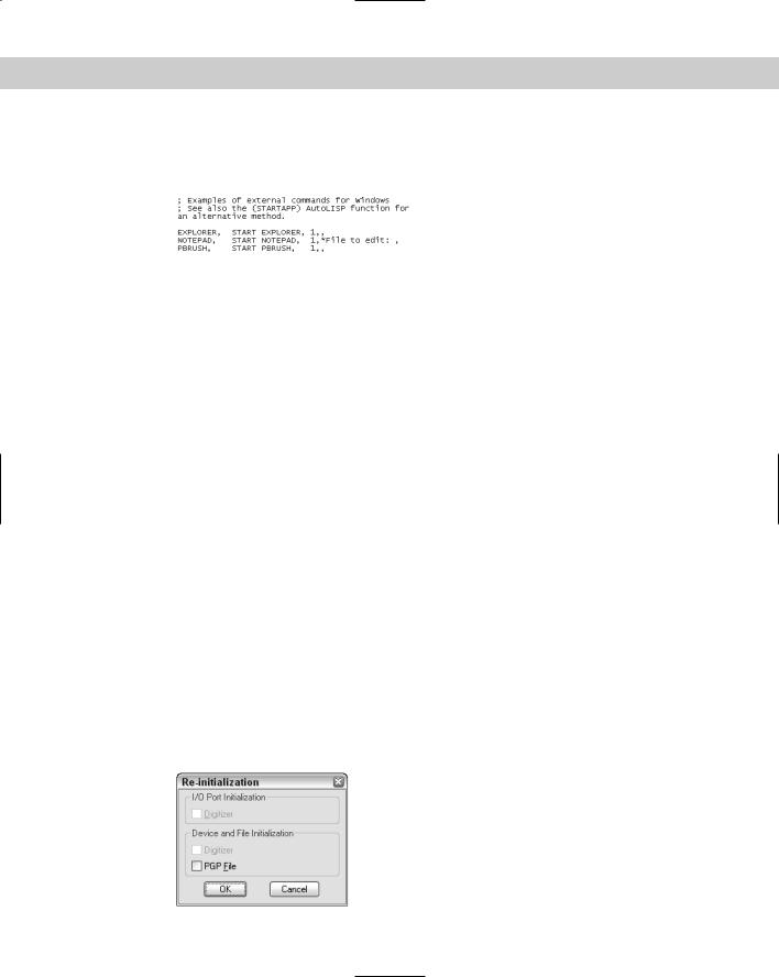
5.In AutoCAD only, scroll down roughly two screens until you see the three Windows commands, as shown in Figure 29-2. Place the cursor at the end of the PBRUSH line and press Enter.
Figure 29-2: The Windows commands in the acad.pgp file.
6.In AutoCAD only, type the following and press Enter (the uppercasing and spaces are used to match the format of the rest of the file):
WORDPAD, START WORDPAD, 1,,
7.Look at the next section of acad.pgp or aclt.pgp. Read the guidelines for creating new aliases.
8.Scroll down until you see the following two lines:
CH, *PROPERTIES -CH, *CHANGE
The alias for the CHANGE command follows the guideline of using a hyphen to distinguish command-line versions of commands. Suppose you have trouble finding that hyphen quickly (you end up typing =ch instead). You want to change the alias to cg (with no hyphen).
9.Scroll down to the end of the file until you see the User Defined Command Aliases section. Place the cursor at the very end of the file and press Enter. Type the following and press Enter (don’t worry about the spaces — I’ve matched the spacing of the acad.pgp or aclt.pgp file):
CG, *CHANGE
10.Choose File Save.
11.Close Notepad. Generally, acad.pgp is accessed only when you load a new or existing
drawing. However, you can use the REINIT command to reload the file at any time. Type reinit . The Re-initialization dialog box opens, as shown in Figure 29-3.
12.Check PGP File and click OK. In your drawing, draw any line.
13.Type cg . The CHANGE command starts. Select the line, right-click to end selection, and pick a new endpoint location. The endpoint of the line changes accordingly.
14.Do not save your drawing.
Figure 29-3: The Re-initialization dialog box.

898 Part VI Customizing AutoCAD
On the |
The edited acad.pgp file is on the CD-ROM in the Results folder. Although you made only |
CD-ROM |
two changes, if you want, you can copy the acad.pgp file from the CD-ROM over your orig- |
|
inal acad.pgp file. Of course, you can make additional changes to suit your needs. |
Customizing Toolbars
In the Windows environment, you frequently find yourself using toolbar buttons for many of your tasks. Nevertheless, how many times have you found yourself typing a command because you couldn’t quickly find an equivalent button on a toolbar, or because it was on a flyout that was too annoying to deal with? In addition, think how often you start a command with a toolbar button, only to return to the keyboard to type in a simple option.
You can customize the toolbars to make your work easier and faster. You can create new toolbars from scratch, or edit existing ones. You can even create your own toolbar buttons. When you create a toolbar button, you can attach any sequence of commands to it — a complex macro or even an AutoLISP expression (for AutoCAD only).
Using the Customize dialog box
The Toolbars tab of the Customize dialog box (choose View Toolbars), shown in Figure 29-4, combines all the tools you need to manage toolbars.
Figure 29-4: The Toolbars tab of the Customize dialog box.
To display a toolbar, you don’t need to use the Toolbars dialog box. You can right-click any toolbar and choose from the list on the shortcut menu. However, you can also display toolbars from the Toolbars tab of the Customize dialog box by checking the toolbar you want to see. Both lists include flyouts. It’s, therefore, very easy to turn a flyout into a toolbar if you want — click the flyout (for example, Zoom) and it appears as a regular toolbar.
You also use the Toolbars tab of the Customize dialog box to create new toolbars, delete toolbars, and customize existing toolbars. If you create your own menus, they can have toolbars as well. You can then choose toolbars from your menus using the Menu Group drop-down list.

Chapter 29 Customizing Commands, Toolbars, and Tool Palettes |
899 |
Creating a new toolbar
You may want to create your own toolbar from scratch that contains buttons for commands that you use often. To create a new toolbar, choose Custom from the Menu Group list.
New |
The Toolbars tab of the Customize dialog box now contains a new menu group, Custom. This |
Feature |
menu group is for toolbars that you create. Using a separate menu group keeps your cus- |
|
|
|
tomization separate from the program’s standard menu files. You use menu groups when you |
|
start to create your own menus. For more on menu groups, see Chapter 33. |
Click New to open the New Toolbar dialog box. Name your toolbar, and then click OK. Your toolbar now appears in the Toolbars list of the Toolbars dialog box, and a small, new toolbar appears on the screen, as shown in Figure 29-5.
|
Figure 29-5: The new toolbar shown in the Toolbar list |
|
and on the screen. |
|
The new toolbar is just a baby, but as you add buttons to it, it grows automatically. |
Tip |
A quick way to create a new toolbar is to use the Commands tab. Find any command and drag |
|
it onto the drawing area to automatically create a new toolbar that includes the command you |
|
chose. However, this method puts the new toolbar in the ACAD or ACLT menu, not the new |
|
CUSTOM menu. Also, to prevent toolbars from taking up valuable real estate on the screen, |
|
you can make several small toolbars and fit them in the blank spaces next to existing toolbars. |
|
Removing buttons |
|
You can customize any existing toolbar by removing buttons that you rarely use. To remove |
|
buttons from a toolbar, follow these steps: |
1.Display the toolbar.
2.Choose View Toolbars to display the Customize dialog box. If necessary, move it out of the way so you can access the toolbar that needs a button removed.
3.Drag the unwanted button off the toolbar and onto the screen area and release the mouse button.
900 Part VI Customizing AutoCAD
Note It’s easy to forget that you need to have the Customize dialog box open to remove buttons, because there’s no direct connection between dragging buttons off the toolbar and the dialog box — but you can’t drag buttons off a toolbar unless the dialog box is open. Inadvertently dragging a button off the Customize Toolbars dialog box is also easy — if you do, you create a new toolbar.
Adding buttons
If you’ve created a new toolbar, you need to add buttons to it. You can do this in several ways:
Add a button from the Commands tab of the Customize dialog box. Display the Commands tab of the Customize dialog box and choose a category. Each category contains a number of preset buttons (including many of the flyout buttons from Release 13). You can also choose All Commands in the Category pane and then choose any command from the alphabetical Commands list. Click a button to see its description at the bottom of the dialog box. When you’ve found the button you want, drag it to your new toolbar.
Move a button from another toolbar. With the Customize Toolbars dialog box open, drag a button from one open toolbar to your new toolbar. This moves the button, deleting it from the original toolbar.
Copy a button from another toolbar. If you want to leave the original toolbar intact, use the same technique as for moving a button, but hold down the Ctrl key as you drag a button from one open toolbar to your new toolbar. This procedure copies the button.
Creating your own button definition
You can also create your own button definition from scratch. Follow these steps:
1.With the Commands tab of the Customize dialog box displayed, choose User Defined from the Categories list. The Commands pane lists a User Defined Button and User Defined Flyout.
2.Drag the button you want onto your toolbar. Because the buttons have no borders, they’re indistinguishable from the background until you click them.
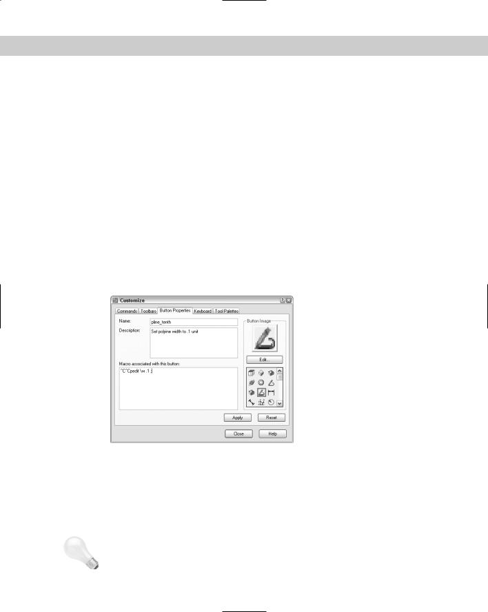
3.Click the Properties tab of the Customize dialog box and then click the blank button to display the Button Properties tab of the Customize dialog box, shown in Figure 29-6.
4.Type a name for the button. This name appears as a tooltip, so don’t make it too long.
5.Type a help description in the Help text box. This text appears on the status line to further explain the function of the button.
6.Write the macro. The ^C^C is already there for you. This cancels any other command that may be active when you use the button. You can place any valid menu command string as it would be typed on the command line or even an AutoLISP expression (for AutoCAD only).
Cross- |
You should use menu syntax for the macro. I explain the details of creating command strings |
Reference |
in Chapter 33, where I cover customizing menus. |
|
Chapter 29 Customizing Commands, Toolbars, and Tool Palettes |
901 |
Figure 29-6: The Button Properties tab of the
Customize dialog box.
7.Choose a button icon from the list of button icons or choose Edit to create your own button, as explained in the next section.
8.Click Apply and click the Close button of the Customize dialog box to close it. Close any other open dialog boxes.
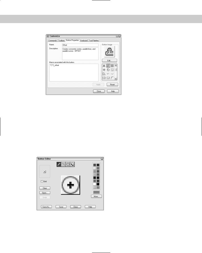
Using the Button Editor
The Button Editor, shown in Figure 29-7, enables you to make your own button icons. Open the Button Editor by clicking Edit on the Button Properties tab of the Customize dialog box. You can choose one of the provided buttons and edit it — which I recommend — or start from scratch if you have artistic tendencies.
Figure 29-7: The Button Editor.

902 Part VI Customizing AutoCAD
The center of the editing area shows an enlarged view of the button. You see the button’s actual size at the top-left corner of the dialog box. Check Grid to show a grid of pixels — this is just for your reference. Choose a color from the color palette and then choose one of the four tools at the top of the dialog box:
The Pencil tool draws any shape. To draw, drag it across the editing area.
Click and drag the Line tool to draw a straight line.
The Circle tool draws circles and ellipses. You click the center and drag out to the circumference to indicate the radius.
The Erase tool erases. You can click to erase pixel by pixel or drag to erase a series of pixels.
Here are the other features of the Button Editor:
Choose Clear to clear the editing area and start from scratch.
Choose Open to open an existing button for editing. Button icons are stored as BMP files.
Choose Undo to undo your most recent action.
Choose Save to save the button icon as a BMP file. The default filename is ICON.bmp.
Choose Save As to save an existing BMP file under a new name.
Choose Close to close the Button Editor.
Choose More to select a standard index color or true color (for AutoCAD only).
Creating flyouts
You can also create your own flyouts, or you can use one of the existing flyouts. To use an existing flyout, open the Commands tab of the Customize dialog box and choose Flyouts. You can simply drag one of these to a toolbar.
To create your own flyout, follow these steps:
1.Create a toolbar with the buttons that you want on the flyout, as explained in the previous section.
2.Open the Customize dialog box and display the Commands tab.
3.Choose User Defined from the Categories list and drag User Defined Flyout from the Commands list onto an existing toolbar. You see a blank flyout on the toolbar.
4.Click the Properties tab of the Customize dialog box and then click the blank flyout button to display the Flyout Properties tab, shown in Figure 29-8.
5.You see a message telling you to associate a toolbar with the flyout.
6.From the list of toolbars, choose the new toolbar that you created. This toolbar will be the flyout from the flyout button you just added.
7.Click Apply and then click Close.
8.Your new toolbar is now a flyout on a toolbar. You can close the new toolbar you created because you can access it from its parent toolbar.

Chapter 29 Customizing Commands, Toolbars, and Tool Palettes |
903 |
Figure 29-8: The Flyout Properties tab of the
Customize dialog box.
The following exercise changes your menu files. After the exercise, I explain how to undo the changes if you want. If you’re working on someone else’s computer, don’t do this exercise without that person’s permission. As I mentioned before, it isn’t good computer etiquette to modify other people’s files without asking first.
New |
Toolbars are easy to customize, but such customization can be a problem in a networked |
Feature |
environment or when more than one person uses the same computer. Most CAD Managers |
|
|
|
don’t want their users making their own customizations. You can now use the TBCUSTOMIZE |
|
system variable (in AutoCAD only) to disable the TOOLBAR and CUSTOMIZE commands, |
|
both of which open the Customize dialog box. |
STEP-BY-STEP: Customizing Toolbars
1.Open Windows Explorer.
•For AutoCAD: Copy acad.mnu, acad.mnc, and acad.mns5 to a floppy disk or CD-ROM.
•For AutoCAD LT: Copy aclt.mnu, aclt.mnc, and aclt.mns to a floppy disk or CD-ROM.
Note |
To find the location of these files, choose Tools Options and click the Files tab. Double-click |
|
the Menu, Help, and Miscellaneous File Names item (in AutoCAD) or the Miscellaneous File |
|
Names item (in AutoCAD LT) to display the location of the menu files. |
2.Start a new drawing using any template. Save the file as ab29-01.dwg in your AutoCAD Bible folder.
3.Choose View Toolbars to open the Customize dialog box. From the Toolbars list, scroll down to find the Zoom toolbar and check it. When it appears, drag it away from the Toolbars dialog box, if necessary.
904 Part VI Customizing AutoCAD
4.Drag the Zoom Center button off the toolbar (or choose the button that you use least and drag it off), and confirm the deletion.
5.From the Menu Group list, choose Custom. Choose New. In the New Toolbar dialog box, type Special in the Toolbar Name text box and click OK. A small toolbar appears on your screen.
6.Click the Commands tab. From the Categories list, choose Draw. Find the Donut button and drag it to your new toolbar. The I-beam cursor on the toolbar indicates the button placement.
7.Choose the Modify category and find Edit Polyline. Drag it to your new toolbar.
8.Choose the View category and drag Hide to the toolbar.
9.Choose the User Defined category and drag User Defined Button to the new toolbar. Click the blank button to display the Button Properties tab.
10.Complete the dialog box, as shown in Figure 29-9. Type the macro as follows after the ^C^C, which is already there, being careful to include the spaces as well:
pedit \w .1 ;
11.Choose the Polyline Edit button from the Button Icon list, as shown in Figure 29-9. Choose Edit to open the Button Editor.
Figure 29-9: The completed Button Properties dialog box.
12.You want to change the button so that it looks as if a zero-width polyline is being changed to a wider polyline because that’s what the macro does. Click the red color. Choose the Pencil tool (by default, it is already chosen). Click Grid to help you work. Click (or drag) the point of the Pencil tool in each box, using Figure 29-10 as a guide. (Figure 29-10 shows the button in black and white.) When you’re done, choose Save and then Close.
Tip |
If you make a mistake, it’s easy to correct it. If you place a red pixel over an existing black pixel, |
|
choose black and redraw the black pixel. If you place a red pixel in a wrong spot, choose the |
|
Erase tool and click the pixel. |

Chapter 29 Customizing Commands, Toolbars, and Tool Palettes |
905 |
Figure 29-10: The new button.
13.On the Button Properties tab, click Apply. The new button appears in your toolbar. Click the Close button to close the dialog box and save the changes to your menu source file (MNS).
14.Dock the new toolbar on the right side of the screen.
15.Choose Polyline from the Draw toolbar and draw any series of polyline segments. Choose the Plines .1 Wide button from the new toolbar. At the Select polyline: prompt, pick the polyline. Its width changes to 0.1. (If it doesn’t work, check the macro. Right-click the Plines .1 Wide button, choose Customize, and click the Pline_tenth button to open the Button Properties tab.)
16.Save your drawing.
Caution |
If you later customize the menu by editing acad.mnu or aclt.mnu, your toolbar modifica- |
|
tions will be erased! In Chapter 33, where I discuss customizing menus, I explain how to avoid |
|
this problem. |
Here’s how the pedit macro you used in the previous Step-by-Step exercise works:
pedit \w .1 ;
1.Pedit issues the PEDIT command. The space after pedit is equivalent to pressing Enter after you’ve typed the command on the command line. PEDIT then displays the
Select polyline: prompt.
2.The backslash (\) is a special character that pauses the macro for your input. When you select the polyline, the macro continues, displaying the Enter an option [Close/ Join/Width/Edit vertex/Fit/Spline/Decurve/Ltype gen/Undo]: prompt.
3.The w then specifies the Width option. The space following it is like pressing Enter.
PEDIT then displays the Specify new width for all segments: prompt.
4.The macro then specifies 0.1. The space after it is like pressing Enter again. PEDIT then issues the Enter an option [Close/Join/Width/Edit vertex/Fit/Spline/ Decurve/Ltype gen/Undo]: prompt.
5.The macro then uses a semicolon, which is used to specify pressing Enter at the end of a menu macro. This ends the command.
906 Part VI Customizing AutoCAD
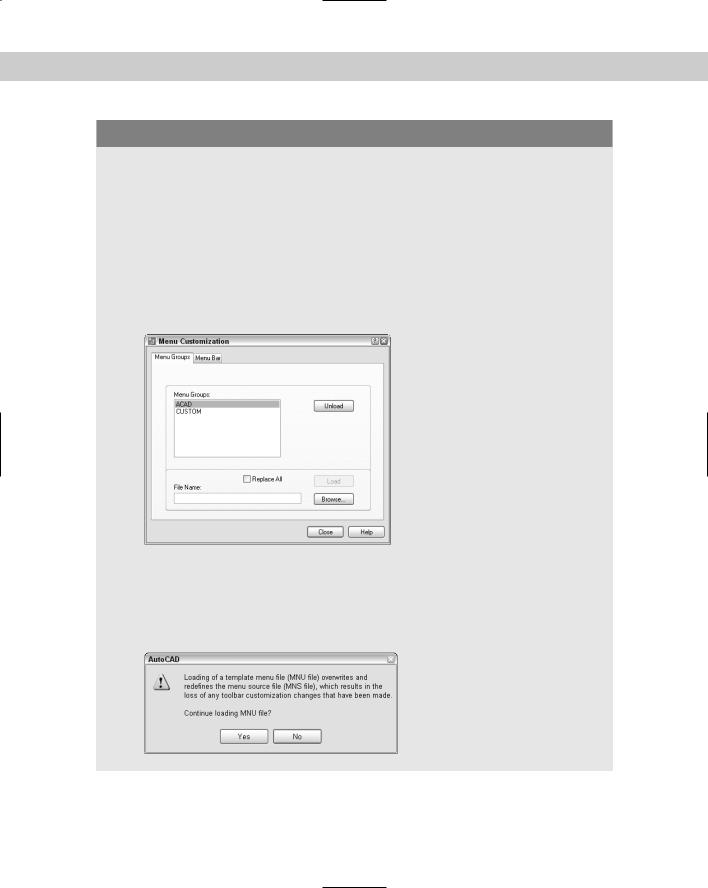
Undoing toolbar changes
In the Step-by-Step exercise on customizing toolbars, you used the separate custom menu to avoid changing the default menu. However, if you change the default menu and want to undo your toolbar changes, you need to reload the template menu, acad.mnu or aclt.mnu. This overwrites the compiled and source menu files that include your toolbar changes. The following steps explain the process. But first, be sure to have a backup of your acad.mnu, acad.mnc, and acad.mns files if you’re using AutoCAD. If you’re using AutoCAD LT make sure to back up the files aclt.mnu, aclt.mnc, and aclt.mns. (To find the location of the menu files, choose Tools Options and click the Files tab. Double-click the Support File Search Path item, to display the location of the menu files.)
1.Choose Tools Customize Menus. The Menu Groups tab should be on top. In the Menu Groups box, ACAD should be highlighted, as shown here.
2.In the bottom section of the dialog box, check Replace All so that all your menu files load on the menu bar. In the File Name box, type acad.mnu or aclt.mnu and click Load. When you load the acad.mnu or aclt.mnu file, a message warns you that you’ll lose any toolbar customization changes you’ve made, as shown in the following figure. Click Yes because you do want to overwrite all your toolbar customization changes.