

- •Foreword
- •Preface
- •Is This Book for You?
- •How This Book Is Organized
- •How to Use This Book
- •Doing the Exercises
- •Conventions Used in This Book
- •What the Icons Mean
- •About the CD-ROM
- •Other Information
- •Contacting the Author
- •Acknowledgments
- •Contents at a Glance
- •Contents
- •Getting Acquainted with AutoCAD and AutoCAD LT
- •Starting AutoCAD and AutoCAD LT
- •Creating a New Drawing
- •Using the AutoCAD and AutoCAD LT Interface
- •Creating Your First Drawing
- •Saving a Drawing
- •Summary
- •Creating a New Drawing from a Template
- •Working with Templates
- •Opening a Drawing with Default Settings
- •Opening an Existing Drawing
- •Using an Existing Drawing as a Prototype
- •Saving a Drawing Under a New Name
- •Summary
- •The Command Line
- •Command Techniques
- •Of Mice and Pucks
- •Getting Help
- •Summary
- •Typing Coordinates
- •Displaying Coordinates
- •Picking Coordinates on the Screen
- •Locating Points
- •Summary
- •Unit Types
- •Drawing Limits
- •Understanding Scales
- •Inserting a Title Block
- •Common Setup Options
- •The MVSETUP Command
- •Summary
- •Using the LINE Command
- •Drawing Rectangles
- •Drawing Polygons
- •Creating Construction Lines
- •Creating Rays
- •Summary
- •Drawing Circles
- •Drawing Arcs
- •Creating Ellipses and Elliptical Arcs
- •Making Donuts
- •Placing Points
- •Summary
- •Panning
- •The ZOOM Command
- •Aerial View
- •Named Views
- •Tiled Viewports
- •Snap Rotation
- •User Coordinate Systems
- •Isometric Drawing
- •Summary
- •Editing a Drawing
- •Selecting Objects
- •Summary
- •Copying and Moving Objects
- •Using Construction Commands
- •Creating a Revision Cloud
- •Hiding Objects with a Wipeout
- •Double-Clicking to Edit Objects
- •Grips
- •Editing with the Properties Palette
- •Selection Filters
- •Groups
- •Summary
- •Working with Layers
- •Changing Object Color, Linetype, and Lineweight
- •Working with Linetype Scales
- •Importing Layers and Linetypes from Other Drawings
- •Matching Properties
- •Summary
- •Drawing-Level Information
- •Object-Level Information
- •Measurement Commands
- •AutoCAD’s Calculator
- •Summary
- •Creating Single-Line Text
- •Understanding Text Styles
- •Creating Multiline Text
- •Creating Tables
- •Inserting Fields
- •Managing Text
- •Finding Text in Your Drawing
- •Checking Your Spelling
- •Summary
- •Working with Dimensions
- •Drawing Linear Dimensions
- •Drawing Aligned Dimensions
- •Creating Baseline and Continued Dimensions
- •Dimensioning Arcs and Circles
- •Dimensioning Angles
- •Creating Ordinate Dimensions
- •Drawing Leaders
- •Using Quick Dimension
- •Editing Dimensions
- •Summary
- •Understanding Dimension Styles
- •Defining a New Dimension Style
- •Changing Dimension Styles
- •Creating Geometric Tolerances
- •Summary
- •Creating and Editing Polylines
- •Drawing and Editing Splines
- •Creating Regions
- •Creating Boundaries
- •Creating Hatches
- •Creating and Editing Multilines
- •Creating Dlines
- •Using the SKETCH Command
- •Digitizing Drawings with the TABLET Command
- •Summary
- •Preparing a Drawing for Plotting or Printing
- •Creating a Layout in Paper Space
- •Working with Plot Styles
- •Plotting a Drawing
- •Summary
- •Combining Objects into Blocks
- •Inserting Blocks and Files into Drawings
- •Managing Blocks
- •Using Windows Features
- •Working with Attributes
- •Summary
- •Understanding External References
- •Editing an Xref within Your Drawing
- •Controlling Xref Display
- •Managing Xrefs
- •Summary
- •Preparing for Database Connectivity
- •Connecting to Your Database
- •Linking Data to Drawing Objects
- •Creating Labels
- •Querying with the Query Editor
- •Working with Query Files
- •Summary
- •Working with 3D Coordinates
- •Using Elevation and Thickness
- •Working with the User Coordinate System
- •Summary
- •Working with the Standard Viewpoints
- •Using DDVPOINT
- •Working with the Tripod and Compass
- •Getting a Quick Plan View
- •Shading Your Drawing
- •Using 3D Orbit
- •Using Tiled Viewports
- •Defining a Perspective View
- •Laying Out 3D Drawings
- •Summary
- •Drawing Surfaces with 3DFACE
- •Drawing Surfaces with PFACE
- •Creating Polygon Meshes with 3DMESH
- •Drawing Standard 3D Shapes
- •Drawing a Revolved Surface
- •Drawing an Extruded Surface
- •Drawing Ruled Surfaces
- •Drawing Edge Surfaces
- •Summary
- •Drawing Standard Shapes
- •Creating Extruded Solids
- •Drawing Revolved Solids
- •Creating Complex Solids
- •Sectioning and Slicing Solids
- •Using Editing Commands in 3D
- •Editing Solids
- •Listing Solid Properties
- •Summary
- •Understanding Rendering
- •Creating Lights
- •Creating Scenes
- •Working with Materials
- •Using Backgrounds
- •Doing the Final Render
- •Summary
- •Accessing Drawing Components with the DesignCenter
- •Accessing Drawing Content with Tool Palettes
- •Setting Standards for Drawings
- •Organizing Your Drawings
- •Working with Sheet Sets
- •Maintaining Security
- •Keeping Track of Referenced Files
- •Handling Errors and Crashes
- •Managing Drawings from Prior Releases
- •Summary
- •Importing and Exporting Other File Formats
- •Working with Raster Images
- •Pasting, Linking, and Embedding Objects
- •Summary
- •Sending Drawings
- •Opening Drawings from the Web
- •Creating Object Hyperlinks
- •Publishing Drawings
- •Summary
- •Working with Customizable Files
- •Creating Keyboard Shortcuts for Commands
- •Customizing Toolbars
- •Customizing Tool Palettes
- •Summary
- •Creating Macros with Script Files
- •Creating Slide Shows
- •Creating Slide Libraries
- •Summary
- •Creating Linetypes
- •Creating Hatch Patterns
- •Summary
- •Creating Shapes
- •Creating Fonts
- •Summary
- •Working with Menu Files
- •Customizing a Menu
- •Summary
- •Introducing Visual LISP
- •Getting Help in Visual LISP
- •Working with AutoLISP Expressions
- •Using AutoLISP on the Command Line
- •Creating AutoLISP Files
- •Summary
- •Creating Variables
- •Working with AutoCAD Commands
- •Working with Lists
- •Setting Conditions
- •Managing Drawing Objects
- •Getting Input from the User
- •Putting on the Finishing Touches
- •Summary
- •Understanding Local and Global Variables
- •Working with Visual LISP ActiveX Functions
- •Debugging Code
- •Summary
- •Starting to Work with VBA
- •Writing VBA Code
- •Getting User Input
- •Creating Dialog Boxes
- •Modifying Objects
- •Debugging and Trapping Errors
- •Moving to Advanced Programming
- •A Final Word
- •Installing AutoCAD and AutoCAD LT
- •Configuring AutoCAD
- •Starting AutoCAD Your Way
- •Configuring a Plotter
- •System Requirements
- •Using the CD with Microsoft Windows
- •What’s on the CD
- •Troubleshooting
- •Index
212 Part II Drawing in Two Dimensions
7.If you want, you can connect the two loose lines that the fillets created and create some more fillets in the drawing.
8.Save your drawing. It should look like Figure 10-34.
Figure 10-34: The filleted drawing.
Creating a Revision Cloud
You may need to mark areas of your drawings that contain revisions, to draw attention to these revisions. A common method is to draw a revision cloud around the revised objects. Figure 10-35 shows a drawing with a revision cloud, which is a series of arcs that indicate that an area of the drawing has been revised.
Figure 10-35: The revision cloud shows where the drawing has been modified.

Chapter 10 Editing Your Drawing: Advanced Tools |
213 |
To create a revision cloud, follow these steps:
1.Choose Revcloud from the Draw toolbar.
2.At the Specify start point or [Arc length/Object/Style] <Object>: prompt, you can choose three options:
•To change the length of the arc, right-click and choose Arc Length. Then specify a new arc length. You can specify a minimum arc length and a maximum arc length that is up to three times the length of the minimum, for a variable, hand-drawn look.
•To change a closed object into a revision cloud, right-click and choose Object. Then pick a circle, ellipse, closed polyline, or closed spline. You can choose to reverse the direction of the revision cloud. The object is converted to a revision cloud and the command ends.
•To choose from two available cloud styles, right-click and choose Style. At the next prompt, choose either the Normal or Calligraphy option. A calligraphy revision cloud has a variable line width so that it looks as if you drew it with a calligraphy pen. The calligraphy style is a new feature of AutoCAD and AutoCAD LT 2005.
3.Click where you want the revision cloud to start. You also see an instruction, Guide crosshairs along cloud path. . ., which means that you don’t have to pick to create the arcs. You just have to move the crosshairs along the path of the desired cloud.
4.Move the crosshairs counterclockwise to create a circular or elliptical shape. When you approach the start point, the command ends automatically. (You can end the cloud at any time by pressing Enter.)
Note If you want, you can pick each arc endpoint to control the size of the arcs. However, if you move the crosshairs farther than the arc length, an arc is created automatically. REVCLOUD multiplies the arc length by the Overall Scale factor (see Chapter 15) to adjust for different scale factors.
Hiding Objects with a Wipeout
A wipeout covers existing objects in order to clear space for some annotation or to indicate that the covered objects will be changed and should, therefore, be ignored. A wipeout is a polygonal area with a background that matches the background of the drawing area. The WIPEOUT command creates a polygon the same color as the background of your drawing area.
To create a wipeout, follow these steps:
1.Choose Draw Wipeout.
2.At the Specify first point or [Frames/Polyline] <Polyline>: prompt, specify the first point of a shape that will cover existing objects. To use a polyline as the shape, right-click and choose Polyline. Then select the polyline and choose whether to erase the polyline or not.
3.At the Specify next point or [Undo]: prompt, if you specified a point, specify the next point.
4.At the Specify next point or [Close/Undo]: prompt, specify another point or use the Close option to close the wipeout shape. You can also press Enter to end the command and use the shape you specified.
214 Part II Drawing in Two Dimensions
By default, the wipeout has a frame around it, using the current layer’s color. You can hide the frames of all wipeouts. Start the WIPEOUT command, choose the Frames option, and choose Off.
Cross- |
You can create a background mask especially for text. This mask covers a rectangle around your |
Reference |
text so that you can read the text more easily. For more information, see Chapter 13. |
|
Double-Clicking to Edit Objects
You can double-click objects to edit them. What happens after you double-click depends on the type of object. In most cases, double-clicking an object just opens the Properties palette where you can change the object’s properties. For example, double-clicking a polyline does not start the PEDIT command, a command for editing polylines. For more information about using the Properties palette, see “Editing with the Properties Palette” later in this chapter.
When you double-click certain types of objects in a drawing, you see a dialog box that is specific to these objects:
Attribute definition: Opens the Edit Attribute Definition dialog box (the DDEDIT command). See Chapter 18 for more information.
Attribute within a block: Opens the Enhanced Attribute Edit dialog box (the EATTEDIT command). See Chapter 18 for more information.
Block: Opens the Reference Edit dialog box (the REFEDIT command). See Chapter 18 for more information.
Hatch: Opens the Hatch Edit dialog box (the HATCHEDIT command). See Chapter 16 for more information.
Mline: Opens the Multiline Edit Tools dialog box (the MLEDIT command). See Chapter 16 for more information.
Mtext or leader text: Opens the Multiline Text Editor (the MTEDIT command). See Chapter 13 for more information.
Text (TEXT or DTEXT commands): Opens the Edit Text dialog box (the DDEDIT command). See Chapter 13 for more information.
Xref: Opens the Reference Edit dialog box (the REFEDIT command). See Chapter 19 for more information.
The DBLCKLEDIT command specifies if double-clicking opens a dialog box in these instances. To turn off double-clicking to edit objects, type dblclkedit and choose the Off option.
Grips
Grips offer a way to edit objects without choosing commands. By using grips, you can quickly stretch, move, rotate, scale, copy, and mirror objects.
When you select an object without first choosing a command, the object appears highlighted with grips — small boxes at preset object snap points. (If you don’t see grips, they may be turned off. See the “Customizing grips” section later in this chapter to find out how to turn them back on.) You can continue to select more objects in this way.
Chapter 10 Editing Your Drawing: Advanced Tools |
215 |
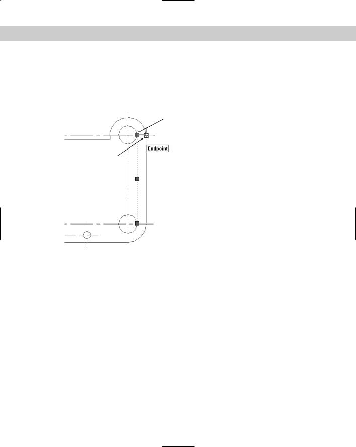
You then activate a grip by clicking it and use the grip to manipulate the object. When the grip is activated, it turns red (by default). An activated grip is also called a hot grip, as shown in Figure 10-36. In some cases, you activate more than one grip at a time. To activate more than one grip, hold down Shift and then click the grips. If you activate a grip in error, click it again to deactivate it. Grips are so called because you can “hold on to” the object by dragging the grips with the mouse.
Hot grip (red)
Crosshairs
 Grip (blue)
Line's original  position
 Line's new position
 Grip (blue)
Figure 10-36: Moving a line. Grips appear at preset object snaps. A hot grip is used to manipulate an object.
After you activate a grip, right-click with the mouse to open the Grip shortcut menu listing all the grip options.
You can also press the Spacebar or Enter to cycle through five possible commands on the command line. As long as you’re familiar with the STRETCH, MOVE, ROTATE, SCALE, and MIRROR commands, you can easily learn how to accomplish the same edits by using grips because the prompts are so similar. After you complete the edit, the object remains highlighted and the grips remain, so that you can further edit the object. If you want to edit another object, press Esc once to remove the grips. Then select another object or objects or choose another command.
Stretching with grips
Stretching with grips involves understanding how the grip points relate to the object. For example, you cannot stretch a line from its midpoint — if you think about it, there’s no way to define in which direction to stretch the line. Also, you cannot stretch a circle. (You can only scale it.) Aside from these types of limitations, anything goes.

216 Part II Drawing in Two Dimensions
Stretching one line
You can stretch one line. The result is similar to using the CHANGE command to change a line’s endpoint. To stretch a line, select it. Click the grip at the endpoint you want to stretch. The prompt on the command line responds with
** STRETCH **
Specify stretch point or [Base point/Copy/Undo/eXit]:
STRETCH is the first grip editing command on the command line. Simply specify the new endpoint for the line, using any method of specifying a coordinate, to stretch the line. The other options work as follows:
Base point lets you define a base point — other than the activated grip — and a second point. Right-click to open the Grip shortcut menu and choose Base Point. The option displays the Specify base point: prompt. Define a base point. Again you see the original Specify stretch point or [Base point/Copy/Undo/eXit]: prompt. Define the second stretch point to stretch the line.
Copy puts you in Multiple mode. Right-click to open the Grip shortcut menu and choose Copy. Again you see the original Specify stretch point or [Base point/ Copy/Undo/eXit]: prompt. Specify a new point to keep the original line and create a new line stretched to the new point. You can continue to create new stretched lines.
Undo undoes the last edit. Right-click to open the Grip shortcut menu and choose Undo.
eXit returns you to the Command prompt. Right-click to open the Grip shortcut menu and choose Exit. Esc also returns you to the Command prompt.
Stretching multiple lines
Stretching more than one line at a time is similar to the most common use of the STRETCH command. However, it can also be somewhat confusing.
As explained earlier in this chapter for the STRETCH command, objects that cross the crossing window are stretched while objects entirely within the crossing window are moved. When you stretch multiple lines, you should activate endpoint grips to stretch lines and activate midpoint grips to move lines. Picking all those grips accurately can be difficult and time-consuming. Also, small objects close together create a lot of overlapping grips that are hard to select. For this reason, stretching multiple lines works best with simple models.
To stretch multiple lines, follow these steps:
1.Choose the objects that you want to stretch. The objects are highlighted and display grips. You can use any method of choosing objects — you aren’t limited to crossing windows.
2.Hold down Shift and pick each grip that you want to stretch. If there are internal objects that you want to move with the stretch, select their grips, too — the midpoints of the lines and arcs, and the centers of the circles.
3.Release Shift and pick a grip to use as a base point. You see the prompt:
** STRETCH **
Specify stretch point or [Base point/Copy/Undo/eXit]:
4. Specify a new stretch point. You can also use any of the other options.
At the end of this section on grips, you have the opportunity to try them out in an exercise.

Chapter 10 Editing Your Drawing: Advanced Tools |
217 |
|
Moving with grips |
|
Moving objects is easy by using grips. Choose all the objects that you want to move. Click any |
|
grip to activate it. This becomes the base point. Right-click to open the Grip shortcut menu |
|
and choose Move. |
Tip |
You can also press the Spacebar to cycle through the grip editing modes. For example, to move |
|
an object, press the Spacebar once. |
|
After you choose Move editing mode, you see the prompt: |
|
** MOVE ** |
|
Specify move point or [Base point/Copy/Undo/eXit]: |
|
Use any method to specify the second point. Be sure to use @ if you’re typing in relative coor- |
|
dinates. The selected objects move. The other options work as follows: |
Base point lets you define a base point — other than the activated grip. Right-click to open the Grip shortcut menu and choose Base Point. You see the Specify base point: prompt. Define a base point. The original Specify move point or [Base
point/Copy/Undo/eXit]: prompt returns. Define the second move point to move the objects.
Copy puts you in Multiple mode and lets you copy objects. Right-click to open the Grip shortcut menu and choose Copy (or type c _). You see the original Specify move point or [Base point/Copy/Undo/eXit]: prompt. Specify a new point to keep the original object and create a new object where you specify. You can continue to create new objects.
Undo undoes the last edit. Right-click to open the Grip shortcut menu and choose Undo.
eXit returns you to the Command prompt. Right-click to open the Grip shortcut menu and choose Exit. Esc also returns you to the Command prompt.
Rotating with grips
Rotating with grips is very similar to using the ROTATE command. Choose all the objects that you want to rotate. Click any grip to activate it. This becomes the base point. Right-click to open the Grip shortcut menu and choose Rotate. You see the prompt:
** ROTATE **
Specify rotation angle or [Base point/Copy/Undo/Reference/eXit]:
Type in a rotation angle or pick a point to rotate the objects. The other options work as follows:
Base point lets you define a base point — other than the activated grip. Right-click to open the Grip shortcut menu and choose Base Point. You see the Specify base point: prompt. Define a base point. The original Specify rotation angle or [Base point/Copy/Undo/Reference/eXit]: prompt returns. Specify the rotation angle to rotate the objects.
Copy puts you in Multiple mode and lets you copy objects. Right-click to open the Grip shortcut menu and choose Copy. Again you see the original Specify rotation angle or [Base point/Copy/Undo/Reference/eXit]: prompt. Specify a rotation angle to keep the original object and create a new rotated object where you specified. You can continue to create new objects.

218 Part II Drawing in Two Dimensions
Undo undoes the last edit. Right-click to open the Grip shortcut menu and choose Undo.
Reference lets you specify a reference angle and a new angle. Right-click to open the Grip shortcut menu and choose Reference. You see the Reference angle <0>: prompt. Type an angle or pick two points to specify an angle. The Specify new angle or [Base point/Copy/Undo/Reference/eXit]: prompt appears. Type an angle or pick a point. This works like the Reference option for the ROTATE command. (See Chapter 9.)
eXit returns you to the Command prompt. Right-click to open the Grip shortcut menu and choose Exit. Esc also returns you to the Command prompt.
Scaling with grips
Scaling with grips is very similar to using the SCALE command. Choose all the objects that you want to scale. Click any grip to activate it. This becomes the base point. Right-click to open the Grip shortcut menu and choose Scale. You see the prompt:
** SCALE **
Specify scale factor or [Base point/Copy/Undo/Reference/eXit]:
Type a scale factor to scale the objects. The other options work as follows:
Base point lets you define a base point — other than the activated grip. Right-click to open the Grip shortcut menu and choose Base Point. You see the Specify base point: prompt. Define a base point. The original Specify scale factor or [Base point/ Copy/Undo/Reference/eXit]: prompt appears. Define the scale factor to scale the objects.
Copy puts you in Multiple mode and lets you copy objects. Right-click to open the Grip shortcut menu and choose Copy. You see the original Specify scale factor or [Base point/Copy/Undo/Reference/eXit]: prompt. Specify a scale factor to keep the original object and create a new scaled object. You can continue to create new scaled objects.
Undo undoes the last edit. Right-click to open the Grip shortcut menu and choose Undo.
Reference lets you specify a reference length and a new scale. Right-click to open the Grip shortcut menu and choose Reference. You see the Reference length <0>: prompt. Type a length or pick two points to specify a length. You see the Specify new length or [Base point/Copy/Undo/Reference/eXit]: prompt. Type a length or pick a point. This works like the Reference option for the SCALE command. (See Chapter 9.)
eXit returns you to the Command prompt. Right-click to open the Grip shortcut menu and choose Exit. Esc also returns you to the Command prompt.
Mirroring with grips
Mirroring with grips is similar to using the MIRROR command. Choose all the objects that you want to mirror. Click any grip to activate it. This becomes the first point of the mirror line. Right-click to open the Grip shortcut menu. Choose Mirror. You see the prompt:
** MIRROR **
Specify second point or [Base point/Copy/Undo/eXit]:

Chapter 10 Editing Your Drawing: Advanced Tools |
219 |
Specify the second point of the mirror line to mirror the objects.
Caution |
By default, AutoCAD and AutoCAD LT erase the original objects. To keep the original objects, |
|
you must use the Copy option. This feature is the opposite of the MIRROR command, where |
|
the default is to keep the original objects. |
The other options work as follows:
On the
CD-ROM
Base point lets you define a base point — other than the activated grip — and a second point. Right-click to open the Grip shortcut menu and choose Base Point. You see the Specify base point: prompt. Define a base point — that is, the first point of the mirror line. The original Specify second point or [Base point/Copy/Undo/eXit]: prompt appears. Define the second point of the mirror line to mirror the objects.
Copy puts you in Multiple mode and lets you keep the original objects. Right-click to open the Grip shortcut menu and choose Copy. You see with the original Specify second point or [Base point/Copy /Undo/eXit]: prompt. Specify the second point to keep the original objects and create new mirrored objects. You can continue to create new mirrored objects.
Undo undoes the last edit. Right-click to open the Grip shortcut menu and choose Undo.
eXit returns you to the Command prompt. Right-click to open the Grip shortcut menu and choose Exit. Esc also returns you to the Command prompt.
The drawing used in the following Step-by-Step exercise on editing with grips, ab10-j.dwg, is in the Drawings folder on the CD-ROM.
STEP-BY-STEP: Editing with Grips
1.Open ab10-j.dwg from the CD-ROM.
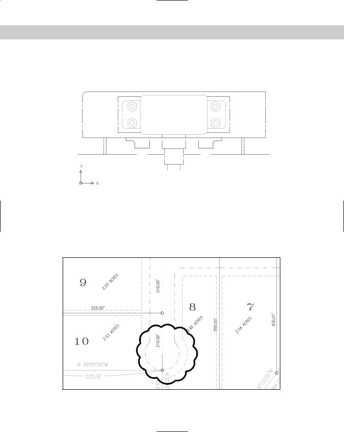
2.Save the file as ab10-12.dwg in your AutoCAD Bible folder. This is a small section of a drive block, seen from above, as shown in Figure 10-37. Make sure ORTHO and OSNAP are on.
3.Use a selection window to select the entire model. Now hold down Shift and place a selection window around the small circles and rectangle at the center of the model to deselect them.
4.Pick the grip at 1 in Figure 10-37 to activate it. You see the following prompt:
** STRETCH **
Specify stretch point or [Base point/Copy/Undo/eXit]:
5. Right-click and choose Mirror from the shortcut menu. You see the following prompt:
** MIRROR **
Specify second point or [Base point/Copy/Undo/eXit]:
6.Right-click and choose Copy so that the original objects that you mirror are not deleted.
220 Part II Drawing in Two Dimensions
7.At the Specify second point or [Base point/Copy/Undo/eXit]: prompt, move the cursor to the right. You can see the mirror image of the model. Pick any point to the right (in the 0-degree direction) of the activated grip.
1 2
Figure 10-37: This small section of a drive block, seen from above, can easily be edited with grips.
8.Right-click and choose Exit to return to the command line. The original objects are still highlighted.
9.Use a large selection window to select all the new objects including the small rectangle and circles in the middle. Everything (old and new) should be highlighted and display grips.
10.Pick the grip at 2 in Figure 10-37 to activate it. Right-click and choose Rotate from the
shortcut menu. At the Specify rotation angle or [Base point/Copy/Undo/ Reference/eXit]: prompt, type 90 . This action rotates the model.
11.Pick the bottom-right grip to activate it. Right-click and choose Scale from the shortcut
menu. At the Specify scale factor or [Base point/Copy/Undo/Reference/ eXit]: prompt, type .5 . This action scales the model.
12.Pick the grip at the midpoint of the bottom line. Right-click and choose Move from the
shortcut menu. At the Specify move point or [Base point/Copy/Undo/eXit]: prompt, type @0,–3 . The model should look like Figure 10-38.
Figure 10-38: The drive block section, after several grip edits, looks a little like a cookie jar.
1
2
Chapter 10 Editing Your Drawing: Advanced Tools |
221 |
13.Press Esc to remove all grips. Define a crossing window by picking first at 1, and then at 2 (see Figure 10-38).
14.Hold down Shift and pick all the grips along the bottom three lines. Release Shift and
pick the grip at the middle of the bottom line. At the Specify stretch point or [Base point/Copy/Undo/eXit]: prompt, type @0,1 to shrink the model.
If the stretch does not come out right (it might be hard to see and activate all the grips), choose Undo from the Standard toolbar to undo the stretch and try again.
15.Save your drawing.
Customizing grips
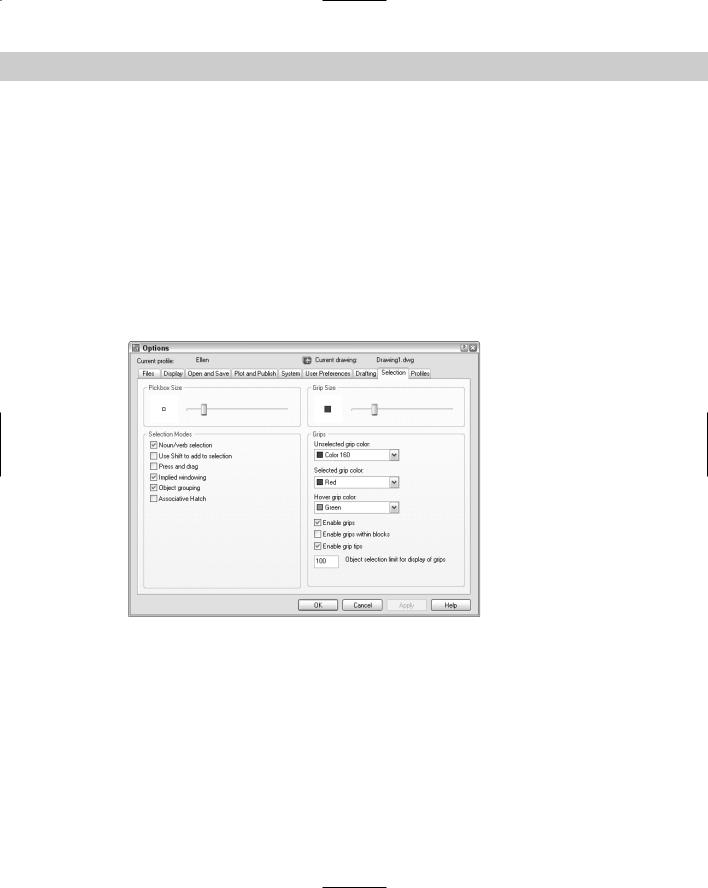
You can turn grips on and off and customize their size and color. Choose Tools Options and click the Selection tab to open the dialog box shown in Figure 10-39.
Figure 10-39: Use the Selection tab of the Options dialog box to customize grips.
By default, grips are enabled (that is, turned on). Also by default, grips are turned off for blocks. (Chapter 18 covers blocks.) When grips are off for blocks, you see only one grip when you select a block — its insertion point. When grips for blocks are on, you see all the grips you would normally see for objects.
In the Grip Colors section, you can choose the colors you want for unselected and selected (hot) grips. Click the drop-down lists to choose a color.
The Grip Size section lets you drag the slider bar to set the size of the grips. Click OK after you’ve made the desired changes.