

- •Foreword
- •Preface
- •Is This Book for You?
- •How This Book Is Organized
- •How to Use This Book
- •Doing the Exercises
- •Conventions Used in This Book
- •What the Icons Mean
- •About the CD-ROM
- •Other Information
- •Contacting the Author
- •Acknowledgments
- •Contents at a Glance
- •Contents
- •Getting Acquainted with AutoCAD and AutoCAD LT
- •Starting AutoCAD and AutoCAD LT
- •Creating a New Drawing
- •Using the AutoCAD and AutoCAD LT Interface
- •Creating Your First Drawing
- •Saving a Drawing
- •Summary
- •Creating a New Drawing from a Template
- •Working with Templates
- •Opening a Drawing with Default Settings
- •Opening an Existing Drawing
- •Using an Existing Drawing as a Prototype
- •Saving a Drawing Under a New Name
- •Summary
- •The Command Line
- •Command Techniques
- •Of Mice and Pucks
- •Getting Help
- •Summary
- •Typing Coordinates
- •Displaying Coordinates
- •Picking Coordinates on the Screen
- •Locating Points
- •Summary
- •Unit Types
- •Drawing Limits
- •Understanding Scales
- •Inserting a Title Block
- •Common Setup Options
- •The MVSETUP Command
- •Summary
- •Using the LINE Command
- •Drawing Rectangles
- •Drawing Polygons
- •Creating Construction Lines
- •Creating Rays
- •Summary
- •Drawing Circles
- •Drawing Arcs
- •Creating Ellipses and Elliptical Arcs
- •Making Donuts
- •Placing Points
- •Summary
- •Panning
- •The ZOOM Command
- •Aerial View
- •Named Views
- •Tiled Viewports
- •Snap Rotation
- •User Coordinate Systems
- •Isometric Drawing
- •Summary
- •Editing a Drawing
- •Selecting Objects
- •Summary
- •Copying and Moving Objects
- •Using Construction Commands
- •Creating a Revision Cloud
- •Hiding Objects with a Wipeout
- •Double-Clicking to Edit Objects
- •Grips
- •Editing with the Properties Palette
- •Selection Filters
- •Groups
- •Summary
- •Working with Layers
- •Changing Object Color, Linetype, and Lineweight
- •Working with Linetype Scales
- •Importing Layers and Linetypes from Other Drawings
- •Matching Properties
- •Summary
- •Drawing-Level Information
- •Object-Level Information
- •Measurement Commands
- •AutoCAD’s Calculator
- •Summary
- •Creating Single-Line Text
- •Understanding Text Styles
- •Creating Multiline Text
- •Creating Tables
- •Inserting Fields
- •Managing Text
- •Finding Text in Your Drawing
- •Checking Your Spelling
- •Summary
- •Working with Dimensions
- •Drawing Linear Dimensions
- •Drawing Aligned Dimensions
- •Creating Baseline and Continued Dimensions
- •Dimensioning Arcs and Circles
- •Dimensioning Angles
- •Creating Ordinate Dimensions
- •Drawing Leaders
- •Using Quick Dimension
- •Editing Dimensions
- •Summary
- •Understanding Dimension Styles
- •Defining a New Dimension Style
- •Changing Dimension Styles
- •Creating Geometric Tolerances
- •Summary
- •Creating and Editing Polylines
- •Drawing and Editing Splines
- •Creating Regions
- •Creating Boundaries
- •Creating Hatches
- •Creating and Editing Multilines
- •Creating Dlines
- •Using the SKETCH Command
- •Digitizing Drawings with the TABLET Command
- •Summary
- •Preparing a Drawing for Plotting or Printing
- •Creating a Layout in Paper Space
- •Working with Plot Styles
- •Plotting a Drawing
- •Summary
- •Combining Objects into Blocks
- •Inserting Blocks and Files into Drawings
- •Managing Blocks
- •Using Windows Features
- •Working with Attributes
- •Summary
- •Understanding External References
- •Editing an Xref within Your Drawing
- •Controlling Xref Display
- •Managing Xrefs
- •Summary
- •Preparing for Database Connectivity
- •Connecting to Your Database
- •Linking Data to Drawing Objects
- •Creating Labels
- •Querying with the Query Editor
- •Working with Query Files
- •Summary
- •Working with 3D Coordinates
- •Using Elevation and Thickness
- •Working with the User Coordinate System
- •Summary
- •Working with the Standard Viewpoints
- •Using DDVPOINT
- •Working with the Tripod and Compass
- •Getting a Quick Plan View
- •Shading Your Drawing
- •Using 3D Orbit
- •Using Tiled Viewports
- •Defining a Perspective View
- •Laying Out 3D Drawings
- •Summary
- •Drawing Surfaces with 3DFACE
- •Drawing Surfaces with PFACE
- •Creating Polygon Meshes with 3DMESH
- •Drawing Standard 3D Shapes
- •Drawing a Revolved Surface
- •Drawing an Extruded Surface
- •Drawing Ruled Surfaces
- •Drawing Edge Surfaces
- •Summary
- •Drawing Standard Shapes
- •Creating Extruded Solids
- •Drawing Revolved Solids
- •Creating Complex Solids
- •Sectioning and Slicing Solids
- •Using Editing Commands in 3D
- •Editing Solids
- •Listing Solid Properties
- •Summary
- •Understanding Rendering
- •Creating Lights
- •Creating Scenes
- •Working with Materials
- •Using Backgrounds
- •Doing the Final Render
- •Summary
- •Accessing Drawing Components with the DesignCenter
- •Accessing Drawing Content with Tool Palettes
- •Setting Standards for Drawings
- •Organizing Your Drawings
- •Working with Sheet Sets
- •Maintaining Security
- •Keeping Track of Referenced Files
- •Handling Errors and Crashes
- •Managing Drawings from Prior Releases
- •Summary
- •Importing and Exporting Other File Formats
- •Working with Raster Images
- •Pasting, Linking, and Embedding Objects
- •Summary
- •Sending Drawings
- •Opening Drawings from the Web
- •Creating Object Hyperlinks
- •Publishing Drawings
- •Summary
- •Working with Customizable Files
- •Creating Keyboard Shortcuts for Commands
- •Customizing Toolbars
- •Customizing Tool Palettes
- •Summary
- •Creating Macros with Script Files
- •Creating Slide Shows
- •Creating Slide Libraries
- •Summary
- •Creating Linetypes
- •Creating Hatch Patterns
- •Summary
- •Creating Shapes
- •Creating Fonts
- •Summary
- •Working with Menu Files
- •Customizing a Menu
- •Summary
- •Introducing Visual LISP
- •Getting Help in Visual LISP
- •Working with AutoLISP Expressions
- •Using AutoLISP on the Command Line
- •Creating AutoLISP Files
- •Summary
- •Creating Variables
- •Working with AutoCAD Commands
- •Working with Lists
- •Setting Conditions
- •Managing Drawing Objects
- •Getting Input from the User
- •Putting on the Finishing Touches
- •Summary
- •Understanding Local and Global Variables
- •Working with Visual LISP ActiveX Functions
- •Debugging Code
- •Summary
- •Starting to Work with VBA
- •Writing VBA Code
- •Getting User Input
- •Creating Dialog Boxes
- •Modifying Objects
- •Debugging and Trapping Errors
- •Moving to Advanced Programming
- •A Final Word
- •Installing AutoCAD and AutoCAD LT
- •Configuring AutoCAD
- •Starting AutoCAD Your Way
- •Configuring a Plotter
- •System Requirements
- •Using the CD with Microsoft Windows
- •What’s on the CD
- •Troubleshooting
- •Index

Chapter 35 Exploring AutoLISP Further 1017
Figure 35-5: The result of the print0to10 function.
Don’t save your drawing.
Managing Drawing Objects
The real power of AutoLISP is in manipulating drawing objects. This section reveals how many of the AutoLISP routines perform their magic. You can get information about an object and then use that information to change the object. You can also create selection sets of objects.
Getting information about an object
Every object in the AutoCAD database has an entity name. This name enables you to reference that object anywhere in your AutoLISP application. To see an example of an entity name, type the following after starting a new drawing:
(command “_line” “3,3” “5,5” “”) (entlast)
AutoLISP responds with an Entity name such as <Entity name: 2ed0520>.
The numbers will probably differ on your system, but using the information returned from ENTLAST enables you to programmatically get or set a variety of options on any given database object by referencing its entity name.
The ENTGET (entity get) function is the key to making modifications to the drawing database. The ENTGET function takes an entity name as its one and only argument. After drawing the line in the preceding steps, type the following:
(setq myline (entget (entlast)))
AutoLISP responds with:
((-1 . <Entity name: 15ac558>) (0 . “LINE”) (330 . <Entity name: 15ac4f8>)(5 . “2B”) (100 . “AcDbEntity”) (67 . 0)
(410 . “Model”) (8 . “0”)(100 . “AcDbLine”) (10 3.0 3.0 0.0) (11 5.0 5.0 0.0) (210 0.0 0.0 1.0))
1018 Part VII Programming AutoCAD
This is a representation of how the line is stored in the AutoCAD drawing database. AutoLISP returned 1 large list that contains 12 smaller lists. Each of the smaller lists is referred to as a group indexed by the first element. The entity name is in group –1. Each of the initial numbers in the small lists represents a different quality of the line. These numbers are called object group codes. The object group codes used most often are listed in Table 35-2.
Table 35-2: Commonly Used AutoCAD Object Group Codes
Group Code |
Description |
|
|
–1 |
Entity name |
0 |
Entity type |
1 |
Text value |
8 |
Layer |
10 |
Start point (or center) |
11 |
Endpoint (or alignment point) |
38 |
Elevation |
39 |
Thickness |
40 |
Radius (or height of text) |
62 |
Color |
67 |
Paper space flag |
|
|
Note As you can see from the 10, 11, and 40 codes, the meaning of the group codes can change depending on the type of object it’s used for.
You can also use Visual LISP to examine an AutoCAD object. Begin by choosing View Browse Drawing Database Browse Selection. At this point, Visual LISP will display a pickbox in your drawing so that you can select an object.
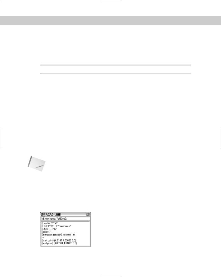
After you end object selection, you’re returned to Visual LISP where you see the Inspect dialog box. Select the name of the entity and, while the cursor is over the selected text, rightclick. Choose Inspect to see information about the object. Figure 35-6 shows information about an arc.
Figure 35-6: Getting information about a drawing object from Visual LISP.

Chapter 35 Exploring AutoLISP Further 1019
Not all these group codes are present in the line you drew. For instance, group 62 (color) is absent in the list returned by AutoLISP. Every time you draw a line, you don’t explicitly set its color. As a result, it defaults to the current color. In the same way, AutoLISP doesn’t explicitly set every attribute of every group. In this case, the color is ByLayer and the current layer is 0. AutoLISP returned (8. “0”) in the preceding list to signify the line is on layer 0.
There are many other group codes than the ones listed in Table 35-2, and they can be found in the Visual LISP Help system. From Visual LISP, choose Help Visual LISP Help Topics. From the Contents tab, double-click DXF Reference. (Because the group codes are also used for DXF files, they’re found in the DXF Reference.) Double-click ENTITIES Section. You can then either choose Common Group Codes for Entities or choose the specific entity you want to look up. In many cases, one group code can have different meanings depending on the entity in which it appears. For example, in the list representing the line you drew, group 10 is represented by (10 3.0 3.0 0.0), which means the start point of the line is at X = 3.0, Y = 3.0, Z = 0.0. If group 0 were a circle instead, the coordinates of group 10 would specify the center point of the circle.
To manipulate a given attribute of an object, two important functions are ASSOC and SUBST:
ASSOC returns a list that finds the entry associated with an item in a list. It takes two arguments — the item in the list and the list itself. For example, if you specify the group code (such as 10) as the first argument, it returns the code’s value (which would be the start point of a line). If a list named myobject contains three groups, as in ((0 . “group 0”) (1 1.0 2.0) (3 4.2 1.5 6.75)), then (assoc 1 myobject) would return (1 1.0 2.0).
SUBST substitutes a value for every occurrence in a list. The SUBST function takes three arguments. To make the substitution, the first argument specifies what to substitute with, the second argument specifies what to substitute for, and the third argument specifies on what list to perform this operation.
To manipulate the start point of your line, first get the start point:
(setq startpt (assoc 10 myline))
AutoLISP responds:
(10 3.0 3.0 0.0)
To modify the start point of your line, use:
(setq new_startpt ‘(10 6.5 1.0 0.0))
(setq myline (subst new_startpt startpt myline))
AutoLISP responds:
((-1 . <Entity name: 15ac558>) (0 . “LINE”) (330 . <Entity name: 15ac4f8>)(5 . “2B”) (100 . “AcDbEntity”) (67 . 0)
(410 . “Model”) (8 . “0”)(100 . “AcDbLine”) (10 6.5 1.0 0.0) (11 5.0 5.0 0.0) (210 0.0 0.0 1.0))
In this case, the new_startpt is substituted for the existing startpt in the object myline. No changes to the line are yet apparent. To commit the change, you need the ENTMOD function.
1020 Part VII Programming AutoCAD
Modifying objects
The key to modifying objects is the ENTMOD (entity modify) function. The list returned by AutoLISP can be modified and then passed to ENTMOD as an argument to update the AutoCAD database. Continuing with the example, if you enter:
(entmod myline)
AutoLISP responds:
((-1 . <Entity name: 15ac558>) (0 . “LINE”) (330 . <Entity name: 15ac4f8>) (5 .”2B”) (100 . “AcDbEntity”) (67 . 0)
(410 . “Model”) (8 . “0”) (100.”AcDbLine”) (10 6.5 1.0 0.0) (11 5.0 5.0 0.0) (210 0.0 0.0 1.0))
The AutoCAD database is changed as well, and the start point of your line is now at X = 6.5, Y = 1.0, Z = 0.0.
Creating selection sets
A selection set is created with the SSGET (selection set get) function. This prompts the user with the familiar Select objects: prompt. Table 35-3 shows the commonly used selectionset functions.
|
Table 35-3: Common AutoCAD Selection-Set Functions |
|
|
Function |
Description |
|
|
SSGET |
Obtains a selection set from the user. |
SSLENGTH |
Returns the number of objects in a selection set. It takes one argument, the |
|
selection set. |
SSNAME |
Returns the entity name of a given object in a selection set. It takes two |
|
arguments: the selection set and the number of the object in the selection set. |
|
The first item number is 0, the second is 1, and so on. |
|
|
You can use a maximum of 256 selection sets at any given time. To release a selection set back to AutoLISP so that it can be used again, set the selection set to nil — for example,
(setq ss nil).
For example, you can enter the following in a new drawing:
(command “_circle” “3,3” “2”) nil
(command “_circle” “4,4” “3”) nil
(command “_line” “7,2” “6,6” “3,4” “5,5” “”) nil
(setq mysset (ssget)) Select objects: all 5 found
Select objects: <Selection set 1>

Chapter 35 Exploring AutoLISP Further 1021
Now mysset is set to the selection set specified by all, which includes the three line segments and the two circles. To see what you have in your selection set, type the following either on the command line or in the Visual LISP Console:
(sslength mysset) 5
You now know that you have five objects in your selection set. The first object is number 0, and the fifth object is number 4. To see what the first object is, enter the following:
(ssname mysset 0) <Entity name: 3fe0550>
To get the database data on the object, enter:
(entget (ssname mysset 0))
Visual LISP responds:
((-1 . <Entity name: 1601580>) (0 . “LINE”) (330 . <Entity name: 16014f8>)(5 . “30”) (100 . “AcDbEntity”) (67 . 0) (410 . “Model”) (8 . “0”)(100 . “AcDbLine”) (10 3.0 4.0 0.0) (11 5.0 5.0 0.0) (210 0.0 0.0 1.0))
By stepping through each of the entity names returned by SSNAME from 0 to 4, you can manipulate each of the objects in the selection set.
STEP-BY-STEP: Creating Selection Sets
1.Start a new drawing using the acad.dwt template, and type the following in a new file in the Visual LISP edit window. Save it as ab35-04.lsp in your AutoCAD 2005Support folder or any folder in the support-file search path.
(defun c:listsset (/ mysset counter) (setq mysset (ssget))
(setq counter 0)
(while (< counter (sslength mysset)) (terpri)
(princ (cdr (assoc 0 (entget (ssname mysset counter))))) (setq counter (+ counter 1))
)
(princ)
)
2.Load ab35-04.lsp.
3.Activate AutoCAD and draw any number of objects on-screen — at least two different types of objects.
4.Type listsset . AutoCAD prompts you to select objects (because of the SSGET function).
5.Select all the objects in your drawing. The routine prints the type of each object you selected. (Press F2 to open the AutoCAD Text Window to see the entire results.) Figure 35-7 shows the result. Of course, your result will be different because you probably drew different types of objects.