

- •Foreword
- •Preface
- •Is This Book for You?
- •How This Book Is Organized
- •How to Use This Book
- •Doing the Exercises
- •Conventions Used in This Book
- •What the Icons Mean
- •About the CD-ROM
- •Other Information
- •Contacting the Author
- •Acknowledgments
- •Contents at a Glance
- •Contents
- •Getting Acquainted with AutoCAD and AutoCAD LT
- •Starting AutoCAD and AutoCAD LT
- •Creating a New Drawing
- •Using the AutoCAD and AutoCAD LT Interface
- •Creating Your First Drawing
- •Saving a Drawing
- •Summary
- •Creating a New Drawing from a Template
- •Working with Templates
- •Opening a Drawing with Default Settings
- •Opening an Existing Drawing
- •Using an Existing Drawing as a Prototype
- •Saving a Drawing Under a New Name
- •Summary
- •The Command Line
- •Command Techniques
- •Of Mice and Pucks
- •Getting Help
- •Summary
- •Typing Coordinates
- •Displaying Coordinates
- •Picking Coordinates on the Screen
- •Locating Points
- •Summary
- •Unit Types
- •Drawing Limits
- •Understanding Scales
- •Inserting a Title Block
- •Common Setup Options
- •The MVSETUP Command
- •Summary
- •Using the LINE Command
- •Drawing Rectangles
- •Drawing Polygons
- •Creating Construction Lines
- •Creating Rays
- •Summary
- •Drawing Circles
- •Drawing Arcs
- •Creating Ellipses and Elliptical Arcs
- •Making Donuts
- •Placing Points
- •Summary
- •Panning
- •The ZOOM Command
- •Aerial View
- •Named Views
- •Tiled Viewports
- •Snap Rotation
- •User Coordinate Systems
- •Isometric Drawing
- •Summary
- •Editing a Drawing
- •Selecting Objects
- •Summary
- •Copying and Moving Objects
- •Using Construction Commands
- •Creating a Revision Cloud
- •Hiding Objects with a Wipeout
- •Double-Clicking to Edit Objects
- •Grips
- •Editing with the Properties Palette
- •Selection Filters
- •Groups
- •Summary
- •Working with Layers
- •Changing Object Color, Linetype, and Lineweight
- •Working with Linetype Scales
- •Importing Layers and Linetypes from Other Drawings
- •Matching Properties
- •Summary
- •Drawing-Level Information
- •Object-Level Information
- •Measurement Commands
- •AutoCAD’s Calculator
- •Summary
- •Creating Single-Line Text
- •Understanding Text Styles
- •Creating Multiline Text
- •Creating Tables
- •Inserting Fields
- •Managing Text
- •Finding Text in Your Drawing
- •Checking Your Spelling
- •Summary
- •Working with Dimensions
- •Drawing Linear Dimensions
- •Drawing Aligned Dimensions
- •Creating Baseline and Continued Dimensions
- •Dimensioning Arcs and Circles
- •Dimensioning Angles
- •Creating Ordinate Dimensions
- •Drawing Leaders
- •Using Quick Dimension
- •Editing Dimensions
- •Summary
- •Understanding Dimension Styles
- •Defining a New Dimension Style
- •Changing Dimension Styles
- •Creating Geometric Tolerances
- •Summary
- •Creating and Editing Polylines
- •Drawing and Editing Splines
- •Creating Regions
- •Creating Boundaries
- •Creating Hatches
- •Creating and Editing Multilines
- •Creating Dlines
- •Using the SKETCH Command
- •Digitizing Drawings with the TABLET Command
- •Summary
- •Preparing a Drawing for Plotting or Printing
- •Creating a Layout in Paper Space
- •Working with Plot Styles
- •Plotting a Drawing
- •Summary
- •Combining Objects into Blocks
- •Inserting Blocks and Files into Drawings
- •Managing Blocks
- •Using Windows Features
- •Working with Attributes
- •Summary
- •Understanding External References
- •Editing an Xref within Your Drawing
- •Controlling Xref Display
- •Managing Xrefs
- •Summary
- •Preparing for Database Connectivity
- •Connecting to Your Database
- •Linking Data to Drawing Objects
- •Creating Labels
- •Querying with the Query Editor
- •Working with Query Files
- •Summary
- •Working with 3D Coordinates
- •Using Elevation and Thickness
- •Working with the User Coordinate System
- •Summary
- •Working with the Standard Viewpoints
- •Using DDVPOINT
- •Working with the Tripod and Compass
- •Getting a Quick Plan View
- •Shading Your Drawing
- •Using 3D Orbit
- •Using Tiled Viewports
- •Defining a Perspective View
- •Laying Out 3D Drawings
- •Summary
- •Drawing Surfaces with 3DFACE
- •Drawing Surfaces with PFACE
- •Creating Polygon Meshes with 3DMESH
- •Drawing Standard 3D Shapes
- •Drawing a Revolved Surface
- •Drawing an Extruded Surface
- •Drawing Ruled Surfaces
- •Drawing Edge Surfaces
- •Summary
- •Drawing Standard Shapes
- •Creating Extruded Solids
- •Drawing Revolved Solids
- •Creating Complex Solids
- •Sectioning and Slicing Solids
- •Using Editing Commands in 3D
- •Editing Solids
- •Listing Solid Properties
- •Summary
- •Understanding Rendering
- •Creating Lights
- •Creating Scenes
- •Working with Materials
- •Using Backgrounds
- •Doing the Final Render
- •Summary
- •Accessing Drawing Components with the DesignCenter
- •Accessing Drawing Content with Tool Palettes
- •Setting Standards for Drawings
- •Organizing Your Drawings
- •Working with Sheet Sets
- •Maintaining Security
- •Keeping Track of Referenced Files
- •Handling Errors and Crashes
- •Managing Drawings from Prior Releases
- •Summary
- •Importing and Exporting Other File Formats
- •Working with Raster Images
- •Pasting, Linking, and Embedding Objects
- •Summary
- •Sending Drawings
- •Opening Drawings from the Web
- •Creating Object Hyperlinks
- •Publishing Drawings
- •Summary
- •Working with Customizable Files
- •Creating Keyboard Shortcuts for Commands
- •Customizing Toolbars
- •Customizing Tool Palettes
- •Summary
- •Creating Macros with Script Files
- •Creating Slide Shows
- •Creating Slide Libraries
- •Summary
- •Creating Linetypes
- •Creating Hatch Patterns
- •Summary
- •Creating Shapes
- •Creating Fonts
- •Summary
- •Working with Menu Files
- •Customizing a Menu
- •Summary
- •Introducing Visual LISP
- •Getting Help in Visual LISP
- •Working with AutoLISP Expressions
- •Using AutoLISP on the Command Line
- •Creating AutoLISP Files
- •Summary
- •Creating Variables
- •Working with AutoCAD Commands
- •Working with Lists
- •Setting Conditions
- •Managing Drawing Objects
- •Getting Input from the User
- •Putting on the Finishing Touches
- •Summary
- •Understanding Local and Global Variables
- •Working with Visual LISP ActiveX Functions
- •Debugging Code
- •Summary
- •Starting to Work with VBA
- •Writing VBA Code
- •Getting User Input
- •Creating Dialog Boxes
- •Modifying Objects
- •Debugging and Trapping Errors
- •Moving to Advanced Programming
- •A Final Word
- •Installing AutoCAD and AutoCAD LT
- •Configuring AutoCAD
- •Starting AutoCAD Your Way
- •Configuring a Plotter
- •System Requirements
- •Using the CD with Microsoft Windows
- •What’s on the CD
- •Troubleshooting
- •Index

Chapter 34 Understanding AutoLISP and Visual LISP Basics |
997 |
Note |
The first character of the string for SUBSTR is number 1. However, other functions that process |
|
elements of a list (such as NTH) count the first element as 0. |
Table 34-3 offers you a few more functions that work with numbers and strings.
|
Table 34-3: AutoLISP Functions for Numbers and Strings |
|
|
Function |
Description |
|
|
ABS |
Returns the absolute value of the argument. (ABS -76) returns 76. |
ASCII |
Returns the ASCII code of a character. (ASCII “B”) returns 66. |
CHR |
Returns the text string for an ASCII code. (CHR 66) returns “B”. (Stands for |
|
character.) |
ATOI |
Converts a string to an integer. (ATOI “2.7”) returns 2. (Stands for ASCII to integer.) |
ATOF |
Converts a string to a real number. (ATOF “7.6”) returns 7.6. (Stands for ASCII to |
|
float, as in floating point — that is, a real number.) |
ITOA |
Converts an integer to a text string. (ITOA 76) returns “76”. (Stands for integer |
|
to ASCII.) |
RTOS |
Converts a real number to a text string, enclosed in quotes. You can add a mode |
|
(1=scientific, 2=decimal, 3=engineering, 4=architectural, 5=fractional) and a |
|
precision. Otherwise, RTOS uses the current settings. (RTOS 87.3 2 2) returns “87.30”. |
|
(RTOS stands for real to string.) |
= |
Equal to. Returns T for true if all arguments are numerically equal. (= 3 3.0) |
|
returns T. If the arguments are not equal, it returns nil. |
/= |
Not equal to. Returns T if all arguments are not numerically equal. (/= 5 6) |
|
returns T. If they are equal, it returns nil. |
< |
Less than. Returns T if each argument is numerically less than the next argument. |
|
Otherwise returns nil. |
> |
Greater than. Returns T if each argument is numerically greater than the next |
|
argument. Otherwise returns nil. |
>= |
Greater than or equal to. Returns T if each argument is numerically greater than |
|
or equal to the next argument. Otherwise returns nil. |
<= |
Less than or equal to. Returns T if each argument is numerically less than or |
|
equal to the next argument. Otherwise returns nil. |
|
|
Using AutoLISP on the Command Line
You can use AutoLISP on the fly in AutoCAD because it is interpreted. By typing an expression on the command line, you get the result immediately. An interpreted language is one in which a single source statement is translated to machine language, executed, and then each subsequent source statement is operated on in the same way. This enables interactive entry of AutoLISP code into AutoCAD.

998 Part VII Programming AutoCAD
The output of an AutoLISP expression can be used in response to AutoCAD prompts as well. For example, you can type (+ 1 7) at the Diameter/<Radius>: prompt of the CIRCLE command for a circle with a radius of 8 units. This capability to place AutoLISP expressions into AutoCAD commands is a very powerful tool.
If you leave out a closing parenthesis, AutoCAD returns (_> when you press Enter. This tells you that one open parenthesis has not been closed. If two open parentheses remain to be closed, AutoCAD responds with ((_>. Just type the correct number of closing parentheses at the command line and press Enter. AutoCAD accepts the expression.
STEP-BY-STEP: Working with Numbers and Text on the Command Line
1.Open a new drawing using any template.
2.Type circle . Follow the prompts:
Specify center point for circle or [3P/2P/Ttr (tan tan radius)]: Pick
any point.
Specify radius of circle or [Diameter]: (– 5 3)
AutoCAD draws a circle with a radius of 2.
3.Type (strcat “This is an example of “ “regular text.”) . Don’t forget the space between of and the quotation mark. When the two phrases are put together, this creates the space between of and regular. AutoCAD returns “This is an example of regular text.”
4.Press the up-arrow key. AutoCAD repeats the last line. Press the left-arrow key to move
to the right of the last r in regular and press Backspace to delete the word regular. Type italic . AutoCAD returns the new string concatenation.
5.Save the drawing in your AutoCAD Bible folder as ab34-02.dwg.
Note |
When you create AutoLISP expressions on the command line or in the Console window, they |
|
aren’t saved with the drawing. They have the same status as any input you type at the com- |
|
mand line. |
Creating AutoLISP Files
|
If you want to use your AutoLISP expressions more than a couple of times, you should save |
|
them in a file. Create the routine in Visual LISP and choose Save File. |
Tip |
A common practice is to consolidate all AutoLISP routines in one folder for ease of use. To do |
|
this, you can create a folder called LISP in any drive or folder where you keep files that you |
|
create and then choose Tools Options. On the Files tab, expand the Support File Search |
|
Path and click Add. Add the path by typing it directly in the edit box or clicking Browse and |
|
navigating to it. |
Because AutoCAD can open multiple drawings, you need to organize your AutoLISP routines based on whether you want them to apply to all drawings or just the first drawing you open.
Chapter 34 Understanding AutoLISP and Visual LISP Basics |
999 |
AutoCAD offers two LSP files that you can use for your AutoLISP routines:
acad.lsp: Use this file for routines that customize the initialization of AutoCAD. acad. lsp is not automatically loaded for every consecutive drawing. For example, if you want to load a special menu for only a specific drawing, you could put the routine in acad.lsp. (You can choose to load acad.lsp with every drawing. Choose Tools Options and click on the System tab. In the General Options section, check the Load acad.lsp with Every Drawing check box.)
acaddoc.lsp: Use this file for routines that customize the initialization of individual drawings. This file is loaded every time a drawing is opened. If you have a menu that contains AutoLISP macros that include variables you want available for all your drawings, put the AutoLISP routines used by the menu in acaddoc.lsp.
Each drawing contains its own AutoLISP environment. AutoLISP files you load in one drawing — and their variables — won’t be accessible to another drawing. To share functions, use (vl-load-all “filename”) instead of (load “filename”), where filename is the name of the AutoLISP file, to “populate” every current drawing, as well as any new drawing you may create. The VL-LOAD-ALL function is equivalent to placing an AutoLISP routine in acaddoc.lsp.
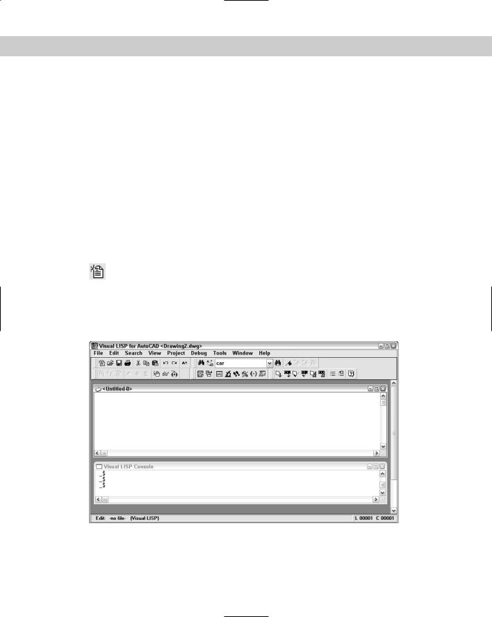
To create a new Visual LISP file, open the Visual LISP Editor (choose Tools AutoLISP Visual LISP Editor) and choose New File on the Standard toolbar. Visual LISP opens an
untitled document, as shown in Figure 34-8. You can now start typing code in the new document. When you start typing, you immediately notice that your code looks different than it would if you had typed it in a text editor — it’s in color! Visual LISP has the capability to distinguish certain features in your code and colors it accordingly. Table 34-4 lists the colors and their meanings.
Figure 34-8: A new AutoLISP document in the Visual LISP editor.
1000 Part VII Programming AutoCAD
Table 34-4: Visual LISP Editor Coloring System |
|
|
|
Color |
AutoLISP Syntax Element |
|
|
Blue |
Built-in functions and protected symbols |
Magenta |
Text strings |
Green |
Integers |
Teal |
Real numbers |
Purple on gray background |
Comments |
Red |
Parentheses |
Black |
Unrecognized items, such as variables you’ve created |
|
|
If you want, you can customize these colors. From the Visual LISP menu, choose Tools Window Attributes Configure Current. In the Window Attributes dialog box, choose an element from the drop-down box and pick a color from the color swatches. You can also change the left margin and the tab width in this dialog box.
STEP-BY-STEP: Creating a New Visual LISP File
1.Start a new drawing using any template. You shouldn’t have any other drawings open.
2.Choose Tools AutoLISP Visual LISP Editor.
3. Choose New File from the Visual LISP Standard toolbar.
4.Type the following:
draws a horizontal line 3 units long (defun c:line3 (/ pt)
(princ "Please pick a point: ") (setq pt (getpoint))
(command "_line" pt "@3,0" "")
)
5.Select the first line of text and choose Comment Block from the Tools toolbar.
6.Choose Format Edit Window from the Tools toolbar to format the code.
7.Choose Check Edit Window and look at the result in the Build Output window.
8.Click the Visual LISP Editor to activate it again.
9.Choose Load Active Edit Window to load the routine.
10.Choose Activate AutoCAD from the View toolbar.
11.On the command line, type line3 .
12.At the Please pick a point: prompt, use any method to specify a point. AutoCAD draws a horizontal line 3 units long.