

- •Foreword
- •Preface
- •Is This Book for You?
- •How This Book Is Organized
- •How to Use This Book
- •Doing the Exercises
- •Conventions Used in This Book
- •What the Icons Mean
- •About the CD-ROM
- •Other Information
- •Contacting the Author
- •Acknowledgments
- •Contents at a Glance
- •Contents
- •Getting Acquainted with AutoCAD and AutoCAD LT
- •Starting AutoCAD and AutoCAD LT
- •Creating a New Drawing
- •Using the AutoCAD and AutoCAD LT Interface
- •Creating Your First Drawing
- •Saving a Drawing
- •Summary
- •Creating a New Drawing from a Template
- •Working with Templates
- •Opening a Drawing with Default Settings
- •Opening an Existing Drawing
- •Using an Existing Drawing as a Prototype
- •Saving a Drawing Under a New Name
- •Summary
- •The Command Line
- •Command Techniques
- •Of Mice and Pucks
- •Getting Help
- •Summary
- •Typing Coordinates
- •Displaying Coordinates
- •Picking Coordinates on the Screen
- •Locating Points
- •Summary
- •Unit Types
- •Drawing Limits
- •Understanding Scales
- •Inserting a Title Block
- •Common Setup Options
- •The MVSETUP Command
- •Summary
- •Using the LINE Command
- •Drawing Rectangles
- •Drawing Polygons
- •Creating Construction Lines
- •Creating Rays
- •Summary
- •Drawing Circles
- •Drawing Arcs
- •Creating Ellipses and Elliptical Arcs
- •Making Donuts
- •Placing Points
- •Summary
- •Panning
- •The ZOOM Command
- •Aerial View
- •Named Views
- •Tiled Viewports
- •Snap Rotation
- •User Coordinate Systems
- •Isometric Drawing
- •Summary
- •Editing a Drawing
- •Selecting Objects
- •Summary
- •Copying and Moving Objects
- •Using Construction Commands
- •Creating a Revision Cloud
- •Hiding Objects with a Wipeout
- •Double-Clicking to Edit Objects
- •Grips
- •Editing with the Properties Palette
- •Selection Filters
- •Groups
- •Summary
- •Working with Layers
- •Changing Object Color, Linetype, and Lineweight
- •Working with Linetype Scales
- •Importing Layers and Linetypes from Other Drawings
- •Matching Properties
- •Summary
- •Drawing-Level Information
- •Object-Level Information
- •Measurement Commands
- •AutoCAD’s Calculator
- •Summary
- •Creating Single-Line Text
- •Understanding Text Styles
- •Creating Multiline Text
- •Creating Tables
- •Inserting Fields
- •Managing Text
- •Finding Text in Your Drawing
- •Checking Your Spelling
- •Summary
- •Working with Dimensions
- •Drawing Linear Dimensions
- •Drawing Aligned Dimensions
- •Creating Baseline and Continued Dimensions
- •Dimensioning Arcs and Circles
- •Dimensioning Angles
- •Creating Ordinate Dimensions
- •Drawing Leaders
- •Using Quick Dimension
- •Editing Dimensions
- •Summary
- •Understanding Dimension Styles
- •Defining a New Dimension Style
- •Changing Dimension Styles
- •Creating Geometric Tolerances
- •Summary
- •Creating and Editing Polylines
- •Drawing and Editing Splines
- •Creating Regions
- •Creating Boundaries
- •Creating Hatches
- •Creating and Editing Multilines
- •Creating Dlines
- •Using the SKETCH Command
- •Digitizing Drawings with the TABLET Command
- •Summary
- •Preparing a Drawing for Plotting or Printing
- •Creating a Layout in Paper Space
- •Working with Plot Styles
- •Plotting a Drawing
- •Summary
- •Combining Objects into Blocks
- •Inserting Blocks and Files into Drawings
- •Managing Blocks
- •Using Windows Features
- •Working with Attributes
- •Summary
- •Understanding External References
- •Editing an Xref within Your Drawing
- •Controlling Xref Display
- •Managing Xrefs
- •Summary
- •Preparing for Database Connectivity
- •Connecting to Your Database
- •Linking Data to Drawing Objects
- •Creating Labels
- •Querying with the Query Editor
- •Working with Query Files
- •Summary
- •Working with 3D Coordinates
- •Using Elevation and Thickness
- •Working with the User Coordinate System
- •Summary
- •Working with the Standard Viewpoints
- •Using DDVPOINT
- •Working with the Tripod and Compass
- •Getting a Quick Plan View
- •Shading Your Drawing
- •Using 3D Orbit
- •Using Tiled Viewports
- •Defining a Perspective View
- •Laying Out 3D Drawings
- •Summary
- •Drawing Surfaces with 3DFACE
- •Drawing Surfaces with PFACE
- •Creating Polygon Meshes with 3DMESH
- •Drawing Standard 3D Shapes
- •Drawing a Revolved Surface
- •Drawing an Extruded Surface
- •Drawing Ruled Surfaces
- •Drawing Edge Surfaces
- •Summary
- •Drawing Standard Shapes
- •Creating Extruded Solids
- •Drawing Revolved Solids
- •Creating Complex Solids
- •Sectioning and Slicing Solids
- •Using Editing Commands in 3D
- •Editing Solids
- •Listing Solid Properties
- •Summary
- •Understanding Rendering
- •Creating Lights
- •Creating Scenes
- •Working with Materials
- •Using Backgrounds
- •Doing the Final Render
- •Summary
- •Accessing Drawing Components with the DesignCenter
- •Accessing Drawing Content with Tool Palettes
- •Setting Standards for Drawings
- •Organizing Your Drawings
- •Working with Sheet Sets
- •Maintaining Security
- •Keeping Track of Referenced Files
- •Handling Errors and Crashes
- •Managing Drawings from Prior Releases
- •Summary
- •Importing and Exporting Other File Formats
- •Working with Raster Images
- •Pasting, Linking, and Embedding Objects
- •Summary
- •Sending Drawings
- •Opening Drawings from the Web
- •Creating Object Hyperlinks
- •Publishing Drawings
- •Summary
- •Working with Customizable Files
- •Creating Keyboard Shortcuts for Commands
- •Customizing Toolbars
- •Customizing Tool Palettes
- •Summary
- •Creating Macros with Script Files
- •Creating Slide Shows
- •Creating Slide Libraries
- •Summary
- •Creating Linetypes
- •Creating Hatch Patterns
- •Summary
- •Creating Shapes
- •Creating Fonts
- •Summary
- •Working with Menu Files
- •Customizing a Menu
- •Summary
- •Introducing Visual LISP
- •Getting Help in Visual LISP
- •Working with AutoLISP Expressions
- •Using AutoLISP on the Command Line
- •Creating AutoLISP Files
- •Summary
- •Creating Variables
- •Working with AutoCAD Commands
- •Working with Lists
- •Setting Conditions
- •Managing Drawing Objects
- •Getting Input from the User
- •Putting on the Finishing Touches
- •Summary
- •Understanding Local and Global Variables
- •Working with Visual LISP ActiveX Functions
- •Debugging Code
- •Summary
- •Starting to Work with VBA
- •Writing VBA Code
- •Getting User Input
- •Creating Dialog Boxes
- •Modifying Objects
- •Debugging and Trapping Errors
- •Moving to Advanced Programming
- •A Final Word
- •Installing AutoCAD and AutoCAD LT
- •Configuring AutoCAD
- •Starting AutoCAD Your Way
- •Configuring a Plotter
- •System Requirements
- •Using the CD with Microsoft Windows
- •What’s on the CD
- •Troubleshooting
- •Index
Chapter 28 Getting on the Internet 865
You’re now back in the Create Transmittal dialog box. Click the Files Table tab to see the files that will be included in your transmittal. The normal files are acad.fmp or aclt.fmp (the font map that specifies font substitutions), SHX files (usually compiled fonts), and any xrefs, raster images, or standards files attached to the drawing. However, eTransmit does not include files referred to by hyperlinks. Therefore, if you want hyperlinks to work, you need to add the referenced files.
To add files, click Add File, navigate to the desired file, select it, and click Open.
To see the Transmittal Report, click the View Report button. The report includes your Notes and instructions to the recipient for using the associated files. For example, there are instructions for where to place SHX files and xrefs. Choose Save As to create an additional copy of the report for your own records.
When you’re done, click OK. If you checked Send E-mail, your e-mail program opens, and you can send an e-mail message and the files. Either way, eTransmit creates the type of transmittal files you requested.
Opening Drawings from the Web
You can access drawings, blocks, and so on from the Internet in the same way you currently access them on your hard drive or network. Sharing drawings around the world can be as easy as opening a drawing on your hard drive. You have two methods for bringing objects from the Internet into your drawings.
Using the Browse the Web – Open dialog box
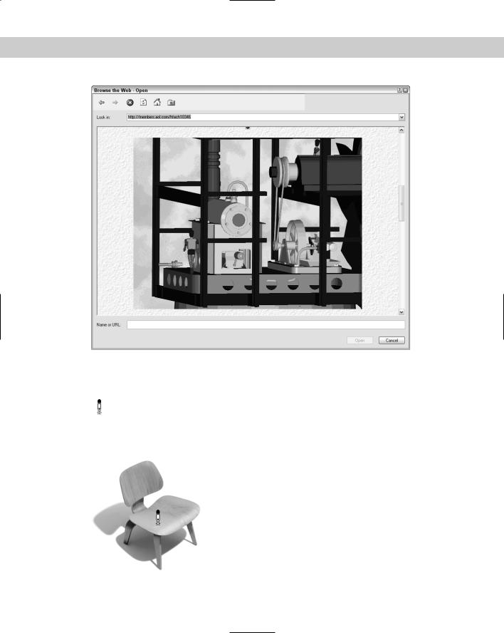
You can directly open a drawing from the Web within the Select File dialog box (choose File Open) by using the Search the Web button. As long as you have an active connec-
tion to the Internet, the Browse the Web – Open dialog box opens, as shown in Figure 28-3. This dialog box functions as a Web-aware Open dialog box, enabling you to access drawings and other files over the Internet.
In the Browse the Web – Open dialog box, use the Look In text box just like the Address box of your Web browser. (The Look In box defaults to the Autodesk Web site.) You can click the down arrow at the right and see the same list of recently used Web addresses (URLs) that you see in your browser. You may need to enter a user name and password, depending on the requirements of the Web site. When you get to the Web page you need, you can click the drawing or its link to place the drawing name in the File Name text box at the bottom of the dialog box. You can also directly type the URL and name of a drawing, such as http://www.rainbow. com/ffairport/hangar-a.dwg. (This is not an existing URL — it’s just an example.)
As soon as you find the drawing you want, click Open. The drawing file opens.
You can do the same with raster images and xrefs. With proper authorization, you can save drawings to a Web URL.
866 Part V Organizing and Managing Drawings
Figure 28-3: The Browse the Web – Open dialog box.
Using i-drop to drag objects into a drawing
An i-drop-enabled Web site displays the i-drop cursor when you pass the cursor over an image, as shown in Figure 28-4. This cursor indicates that you can drag the object represented by the image into your drawing. For more information on creating i-drop-enabled Web
sites, go to http://idrop.autodesk.com. The Publish to Web feature, covered later in this chapter, also contains i-drop capability.
Figure 28-4: Dragging an object from an i-drop-enabled Web site.
Thanks to Eric Stover of Autodesk for permission to display this i-drop example from the Autodesk i-drop Web site.
Chapter 28 Getting on the Internet 867
If you drag with the right mouse button, a prompt asks you if you want to save associated blocks or data when you drag with the right mouse button. Also, inserted blocks automatically include a hyperlink to the source of the content.
Creating Object Hyperlinks
You can insert hyperlinks between objects in your drawing and files or Web sites that may be located anywhere on the Internet, a network, or your own hard drive. A hyperlink creates a permanent connection between your drawing and other files that may provide supporting documentation or additional information.
When you follow a hyperlink, the appropriate application is opened with the specified file. For example, a Web site is opened with your Web browser, and a word processing document is opened with your word processing application.
Creating a hyperlink
Before you create your hyperlink, consider the environment in which it will be used. The file or Web page you’re linking to must be available for the hyperlink to work. If you send a drawing with hyperlinks to a colleague, for example, be sure to include the files that the hyperlinks refer to. If you’re posting the drawing on a Web site as a DWF file, you need to upload the files the hyperlinks refer to along with the DWF file.
Here’s how you create a hyperlink:
1.Select one or more objects in your drawing. The hyperlink will be attached to these objects.
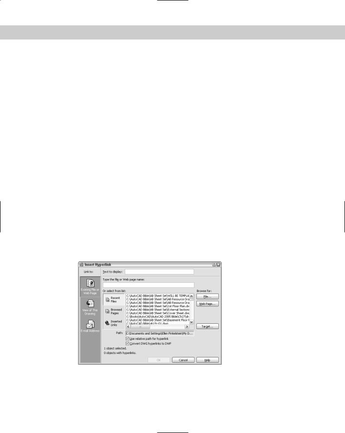
2.Choose Insert Hyperlink (or Ctrl+K) to open the Insert Hyperlink dialog box, shown in Figure 28-5. (If you start the command first, select objects at the prompt.)
Figure 28-5: The Insert Hyperlink dialog box attaches hyperlinks to objects in your drawing.

868 Part V Organizing and Managing Drawings
3.Use the Link To list to choose the type of hyperlink you want to create. The central portion of the dialog box changes depending on which of these options you choose: a Web page, named view, or e-mail address.
•Existing File or Web Page: Creates a hyperlink to another file (on your own computer, network, intranet, or the Internet) or a Web page. You can choose from Recent Files, Browsed Pages, or Inserted Links.
•View of This Drawing: Creates a hyperlink to a named view or layout in the open drawing. You can use this to help viewers navigate to detail views or schedules (tables of data) in the drawing.
•E-mail Address: Opens the viewer’s e-mail program and starts a new message to the address specified.
4.To help you specify the file or Web page, click either the File button or the Web Page button at the right side of the dialog box. To specify a named view in a drawing, click the Target button. In the Select Place in Document dialog box, click the plus sign next to the layout and select a view. Click OK.
5.In the Text to Display text box, type a short description of the hyperlink. If you don’t create a description, when you pass the cursor over the hyperlink, the tooltip lists the URL or filename. If the URL or filename may be confusing, use a description instead. The description is displayed as the tooltip.
6.Uncheck Use Relative Path for Hyperlink if you want to use the entire path you placed in the Link to File or URL text box. A relative path uses a base as a given, requiring you to only specify the part of the path after the base. Use relative paths when you’re working from a company intranet, for example, and all the URLs have the same base, or when the hyperlinked file is in the same folder as the drawing.
7.Uncheck the Convert DWG Hyperlink to DWF check box if you don’t want to retain the hyperlinks if you create a DWF file from the drawing. Usually, you want to leave this check box checked.
8.Click OK to create the hyperlink.
Note |
You set the base path using the HYPERLINKBASE system variable. By default, the base is the |
|
folder of the current drawing. |
Check the hyperlink by passing the cursor over the object to which you attached the hyperlink. You see the Web cursor, shown in Figure 28-6.
Using a hyperlink
After you create a hyperlink, you can use it at any time to open the associated file or move to the associated location within the drawing. If you use a dial-up connection to the Internet and open a drawing with hyperlinks to the Internet while not connected, you’re prompted to connect.
To open a file associated with a hyperlink, Ctrl+click any hyperlinked object. Remember that you can’t just click a hyperlink as you do on a Web site because that just selects the object in your drawing.
Chapter 28 Getting on the Internet 869
Figure 28-6: The Web cursor appears when you pass the cursor over a hyperlinked object.
Editing a hyperlink
To edit any feature of a hyperlink, select the hyperlinked object and choose Insert Hyperlink. You can also right-click and choose Hyperlink Edit Hyperlink. The Edit Hyperlink dialog box opens. This dialog box is the same as the Insert Hyperlink dialog box and lets you edit the hyperlink. Click OK when you’re done.
On the |
The files used in the following Step-by-Step exercise on creating hyperlinks, ab28-a.dwg, |
CD-ROM |
ab28-a.txt, and ab28-b.dwf, are in the Drawings folder on the CD-ROM. |
STEP-BY-STEP: Creating Hyperlinks
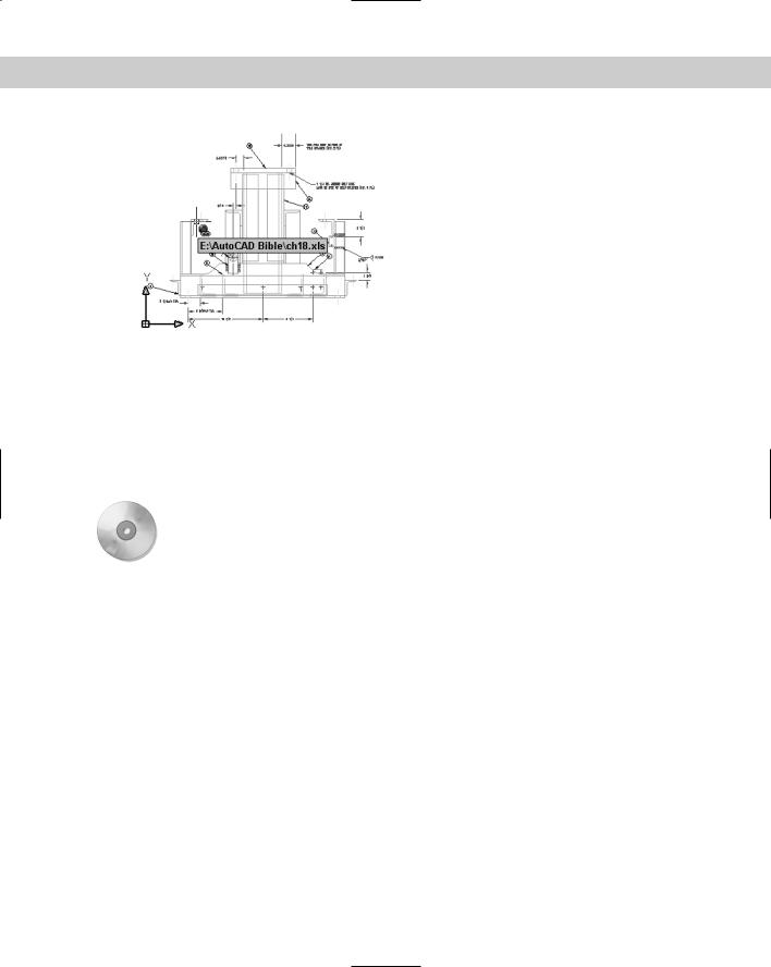
1.Open ab28-a.dwg from the CD-ROM.
2.Save the file as ab28-01.dwg in your AutoCAD Bible folder. This is a 3D drawing of a base assembly frame for an industrial washer, shown in Figure 28-7.
3.Copy ab28-a.txt and ab28-b.dwf from the CD-ROM to your AutoCAD Bible folder. (You can use Windows Explorer to drag the files.)
4.Choose Insert Hyperlink. At the Select objects: prompt, pick 1 and 2 in Figure 28-7. The Insert Hyperlink dialog box opens.
5.Click File. Choose ab28-a.txt in your AutoCAD Bible folder. Click Open. Click OK in the Edit Hyperlink dialog box.
6.Repeat the HYPERLINK command. This time attach 3 and 4 in Figure 28-7 to ab28-b.dwf in your AutoCAD Bible folder. Click OK to close the dialog box.
7.Pass the cursor over all four objects to check the hyperlinks.
8.Save your drawing. Keep it open if you’re going on to the next Step-by-Step exercise.