

- •Foreword
- •Preface
- •Is This Book for You?
- •How This Book Is Organized
- •How to Use This Book
- •Doing the Exercises
- •Conventions Used in This Book
- •What the Icons Mean
- •About the CD-ROM
- •Other Information
- •Contacting the Author
- •Acknowledgments
- •Contents at a Glance
- •Contents
- •Getting Acquainted with AutoCAD and AutoCAD LT
- •Starting AutoCAD and AutoCAD LT
- •Creating a New Drawing
- •Using the AutoCAD and AutoCAD LT Interface
- •Creating Your First Drawing
- •Saving a Drawing
- •Summary
- •Creating a New Drawing from a Template
- •Working with Templates
- •Opening a Drawing with Default Settings
- •Opening an Existing Drawing
- •Using an Existing Drawing as a Prototype
- •Saving a Drawing Under a New Name
- •Summary
- •The Command Line
- •Command Techniques
- •Of Mice and Pucks
- •Getting Help
- •Summary
- •Typing Coordinates
- •Displaying Coordinates
- •Picking Coordinates on the Screen
- •Locating Points
- •Summary
- •Unit Types
- •Drawing Limits
- •Understanding Scales
- •Inserting a Title Block
- •Common Setup Options
- •The MVSETUP Command
- •Summary
- •Using the LINE Command
- •Drawing Rectangles
- •Drawing Polygons
- •Creating Construction Lines
- •Creating Rays
- •Summary
- •Drawing Circles
- •Drawing Arcs
- •Creating Ellipses and Elliptical Arcs
- •Making Donuts
- •Placing Points
- •Summary
- •Panning
- •The ZOOM Command
- •Aerial View
- •Named Views
- •Tiled Viewports
- •Snap Rotation
- •User Coordinate Systems
- •Isometric Drawing
- •Summary
- •Editing a Drawing
- •Selecting Objects
- •Summary
- •Copying and Moving Objects
- •Using Construction Commands
- •Creating a Revision Cloud
- •Hiding Objects with a Wipeout
- •Double-Clicking to Edit Objects
- •Grips
- •Editing with the Properties Palette
- •Selection Filters
- •Groups
- •Summary
- •Working with Layers
- •Changing Object Color, Linetype, and Lineweight
- •Working with Linetype Scales
- •Importing Layers and Linetypes from Other Drawings
- •Matching Properties
- •Summary
- •Drawing-Level Information
- •Object-Level Information
- •Measurement Commands
- •AutoCAD’s Calculator
- •Summary
- •Creating Single-Line Text
- •Understanding Text Styles
- •Creating Multiline Text
- •Creating Tables
- •Inserting Fields
- •Managing Text
- •Finding Text in Your Drawing
- •Checking Your Spelling
- •Summary
- •Working with Dimensions
- •Drawing Linear Dimensions
- •Drawing Aligned Dimensions
- •Creating Baseline and Continued Dimensions
- •Dimensioning Arcs and Circles
- •Dimensioning Angles
- •Creating Ordinate Dimensions
- •Drawing Leaders
- •Using Quick Dimension
- •Editing Dimensions
- •Summary
- •Understanding Dimension Styles
- •Defining a New Dimension Style
- •Changing Dimension Styles
- •Creating Geometric Tolerances
- •Summary
- •Creating and Editing Polylines
- •Drawing and Editing Splines
- •Creating Regions
- •Creating Boundaries
- •Creating Hatches
- •Creating and Editing Multilines
- •Creating Dlines
- •Using the SKETCH Command
- •Digitizing Drawings with the TABLET Command
- •Summary
- •Preparing a Drawing for Plotting or Printing
- •Creating a Layout in Paper Space
- •Working with Plot Styles
- •Plotting a Drawing
- •Summary
- •Combining Objects into Blocks
- •Inserting Blocks and Files into Drawings
- •Managing Blocks
- •Using Windows Features
- •Working with Attributes
- •Summary
- •Understanding External References
- •Editing an Xref within Your Drawing
- •Controlling Xref Display
- •Managing Xrefs
- •Summary
- •Preparing for Database Connectivity
- •Connecting to Your Database
- •Linking Data to Drawing Objects
- •Creating Labels
- •Querying with the Query Editor
- •Working with Query Files
- •Summary
- •Working with 3D Coordinates
- •Using Elevation and Thickness
- •Working with the User Coordinate System
- •Summary
- •Working with the Standard Viewpoints
- •Using DDVPOINT
- •Working with the Tripod and Compass
- •Getting a Quick Plan View
- •Shading Your Drawing
- •Using 3D Orbit
- •Using Tiled Viewports
- •Defining a Perspective View
- •Laying Out 3D Drawings
- •Summary
- •Drawing Surfaces with 3DFACE
- •Drawing Surfaces with PFACE
- •Creating Polygon Meshes with 3DMESH
- •Drawing Standard 3D Shapes
- •Drawing a Revolved Surface
- •Drawing an Extruded Surface
- •Drawing Ruled Surfaces
- •Drawing Edge Surfaces
- •Summary
- •Drawing Standard Shapes
- •Creating Extruded Solids
- •Drawing Revolved Solids
- •Creating Complex Solids
- •Sectioning and Slicing Solids
- •Using Editing Commands in 3D
- •Editing Solids
- •Listing Solid Properties
- •Summary
- •Understanding Rendering
- •Creating Lights
- •Creating Scenes
- •Working with Materials
- •Using Backgrounds
- •Doing the Final Render
- •Summary
- •Accessing Drawing Components with the DesignCenter
- •Accessing Drawing Content with Tool Palettes
- •Setting Standards for Drawings
- •Organizing Your Drawings
- •Working with Sheet Sets
- •Maintaining Security
- •Keeping Track of Referenced Files
- •Handling Errors and Crashes
- •Managing Drawings from Prior Releases
- •Summary
- •Importing and Exporting Other File Formats
- •Working with Raster Images
- •Pasting, Linking, and Embedding Objects
- •Summary
- •Sending Drawings
- •Opening Drawings from the Web
- •Creating Object Hyperlinks
- •Publishing Drawings
- •Summary
- •Working with Customizable Files
- •Creating Keyboard Shortcuts for Commands
- •Customizing Toolbars
- •Customizing Tool Palettes
- •Summary
- •Creating Macros with Script Files
- •Creating Slide Shows
- •Creating Slide Libraries
- •Summary
- •Creating Linetypes
- •Creating Hatch Patterns
- •Summary
- •Creating Shapes
- •Creating Fonts
- •Summary
- •Working with Menu Files
- •Customizing a Menu
- •Summary
- •Introducing Visual LISP
- •Getting Help in Visual LISP
- •Working with AutoLISP Expressions
- •Using AutoLISP on the Command Line
- •Creating AutoLISP Files
- •Summary
- •Creating Variables
- •Working with AutoCAD Commands
- •Working with Lists
- •Setting Conditions
- •Managing Drawing Objects
- •Getting Input from the User
- •Putting on the Finishing Touches
- •Summary
- •Understanding Local and Global Variables
- •Working with Visual LISP ActiveX Functions
- •Debugging Code
- •Summary
- •Starting to Work with VBA
- •Writing VBA Code
- •Getting User Input
- •Creating Dialog Boxes
- •Modifying Objects
- •Debugging and Trapping Errors
- •Moving to Advanced Programming
- •A Final Word
- •Installing AutoCAD and AutoCAD LT
- •Configuring AutoCAD
- •Starting AutoCAD Your Way
- •Configuring a Plotter
- •System Requirements
- •Using the CD with Microsoft Windows
- •What’s on the CD
- •Troubleshooting
- •Index

Chapter 10 Editing Your Drawing: Advanced Tools |
235 |
Select Group: To select the group from the Group Manager, select the group name and click the Select Group button.
Deselect Group: Deselects the group.
To toggle a group from selectable to not selectable, click the group’s icon in the Selectable column. When a group is not selectable, you can individually select its objects.
Using groups
Using a group is very simple. If a group is selectable, just pick any object in the group to select all the objects in a group. You can then edit the objects in the group as a whole. If you need to temporarily edit one object in a group, turn off the group’s selectability, as described in the previous sections.
You can change the selectable status of all groups in your drawing by choosing Tools Options and clicking the Selection tab. Deselect Object Grouping in the Selection Modes section to disable object grouping entirely.
Summary
This chapter covered all the more-advanced editing commands. You read about:
Mirroring objects
Creating rectangular and polar arrays
Creating an offset of an object
Aligning objects
Trimming and extending objects
Stretching objects
Lengthening (and shortening) objects
Breaking objects
Creating chamfered corners and fillets for square, beveled, and rounded corners
Using grips to stretch, move, mirror, rotate, and scale objects
Double-clicking objects to edit them
Using the Properties palette to see the properties of objects and to edit objects
Creating filtered sets of selected objects with the Quick Select feature and the FILTER command
Creating and using named groups of objects
In the next chapter, I cover layers, colors, linetypes, and lineweights.
|
|
|


Organizing
Drawings with
Layers, Colors,
Linetypes, and
Lineweights
Until now, you have drawn everything in black or white. Drawing everything in one color is not a very good way to draw — besides,
it’s boring! If everything is the same color, it’s hard to distinguish the various elements of a drawing. If you’ve followed the exercises throughout this book, you’ve opened some drawings from the CD-ROM that used various colors and linetypes (such as dashed lines). For example, in some of the architectural drawings, you may have noticed that the walls are a different color than the fixtures (refrigerator, sink, and so on) in the kitchen. When you start to create text and dimensions, covered in Chapters 13, 14, and 15, you will almost always use a color that stands out from the main model you’re drawing. You can also create objects with varying widths, called lineweights. This use of color, linetype, and lineweight helps to organize your drawings, making them easier to understand.
In AutoCAD and AutoCAD LT, black and white are the same color. If you use the default background of black, the default color is white. If you change the background to white, the same objects appear as black.
Most often, you assign color, linetype, and lineweight to a layer. A layer is simply an organizational tool that lets you organize the display of objects in your drawing. Every object must have a layer, and every layer must have a color, a linetype, and a lineweight. You define layers that meet your drawing needs. Layers, colors, linetypes, and lineweights are called object properties. You can easily change any object’s properties. This chapter explains how to create and change these object properties to organize your drawing.
11C H A P T E R
In This Chapter
Organizing your drawing
Working with layers
Changing object color, linetype, and lineweight
Working with linetype scales
Importing layers and linetypes from other drawings
Matching properties
238 Part II Drawing in Two Dimensions
Working with Layers
The best way to organize your drawing into colors, linetypes, and lineweights is to use layers. Layers offer powerful features that enable you to distinguish all the various elements of your drawing. In an architectural drawing, for example, common layers are walls, doors, windows, plumbing, electrical, fixtures, structural elements, notes (text), dimensions, and so on.
Mechanical drawings might use center, hidden, hatch, object, and title block layers. Each discipline has its own conventions, and you might have specific conventions where you work.
Creating layers is an important part of setting up a drawing, in addition to the setup features covered in Chapter 5. Layers should be created and saved in your templates so that they’re available to you when you start to draw.
Layers give you many ways to organize your drawing. For example, you can
Cross-
Reference
Assign different colors, linetypes, and lineweights to layers.
Assign the various colors to different pens in a pen plotter, resulting in a drawing with varying colors or line widths.
Control the visibility of layers. Making a layer invisible lets you focus on just the objects that you need to draw or edit.
Control which objects are plotted.
Lock a layer so that objects on that layer cannot be edited.
You can also assign a plot style to a layer. A plot style is a group of settings that affects how your drawing is plotted. Chapter 17 covers plot styles.
Understanding layers
Besides having a color, linetype, and lineweight, every layer must have a name. All drawings come with a default layer, called layer 0 (zero). Its color is Black/white, its linetype is Continuous, and its lineweight is Default. (The lineweight for Default is 0.010 inch or 0.25 mm.) All the exercises in this book up to this point have used layer 0. To create a new layer, you must give it a name, a color, a linetype, and a lineweight. You can then start drawing on that layer.
Layers also have four states. These states control visibility, regeneration, editability, and plottability of layers:
On/Off: On layers (the default) are visible. Off layers are invisible and are regenerated with the drawing.
Thawed/Frozen: Thawed layers (the default) are visible. Frozen layers are invisible and are not regenerated with the drawing. However, when you thaw a frozen layer, the drawing regenerates. If you have floating viewports (covered in Chapter 17), you can also freeze a layer just in the current viewport, or only for new viewports that you create.
Unlocked/Locked: Unlocked layers (the default) are visible and editable. Locked layers are visible but cannot be edited.
Plottable/Not Plottable: Plottable layers are plotted. Not plottable layers are not plotted. This setting affects only layers that are on or thawed because off and frozen layers are not plotted anyway.
Chapter 11 Organizing Drawings with Layers, Colors, Linetypes, and Lineweights |
239 |
Creating new layers
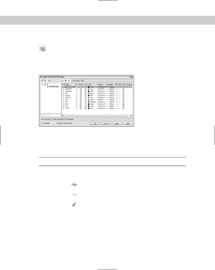
To create a new layer, choose Layer Properties Manager from the Layers toolbar. The Layer Properties Manager dialog box opens, as shown in Figure 11-1. From this point on,
I’ll just call this dialog box, the Layer Properties Manager. This dialog box lists all current layers and their properties. You can also create new layers and modify current ones. The left panel allows you to filter the list of layers. For more information, see “Filtering the layer list” later in this chapter.
Figure 11-1: The Layer Properties Manager is the place to manage all your layers.
Table 11-1 explains the columns in the dialog box. For a description of the icons in most of the columns, see Table 11-2.
Table 11-1: Columns in the Layer Properties Manager
Column Name |
Description |
|
|
Status |
Shows the status of each layer. |
|
Used layer. |
|
Unused layer. |
|
Current layer. |
Name |
Shows the name of the layer. To change the layer, click once to display a border |
|
and click again to type a new name. |
On |
Shows the current on/off state of a layer. Click to turn the layer on or off. |
Freeze |
Shows the current freeze/thaw state of a layer. Click to freeze or thaw a layer. |
Lock |
Shows the current locked/unlocked state of a layer. Click to lock or unlock a layer. |
Color |
Shows the current color of the layer. Click to change the color. |
Continued
240 Part II Drawing in Two Dimensions
|
Table 11-1 (continued) |
|
|
Column Name |
Description |
|
|
Linetype |
Shows the current linetype of the layer. Click to change the linetype. |
Lineweight |
Shows the current lineweight of the layer. Click to choose a new lineweight. |
Plot Style |
Shows the current plot style of the layer. Click to select a new plot style. (Chapter |
|
17 covers plot styles). |
Plot |
Shows the current plottable/not plottable state of the layer. Click to make the layer |
|
plottable or not plottable. |
Current VP Freeze |
Shows the freeze/thaw state of the layer in the current floating viewport. Click to |
|
freeze or thaw the layer in active floating viewports. This column is displayed only if |
|
you have floating viewports and a layout tab is active. (Chapter 17 covers floating |
|
viewports.) |
New VP Freeze |
Shows the current freeze/thaw state of the layer in new floating viewports that you |
|
create. Click to freeze or thaw the layer in new viewports. This column is displayed |
|
only if you have floating viewports and a plot layout is active. (Chapter 17 covers |
|
floating viewports.) |
Description |
Provides a place to enter a description of a layer. |
|
|
To adjust the display in the Layer Properties Manager, you can do the following:
Change the width of any column in the Layer Properties Manager by placing the cursor over the line dividing two column headings and dragging.
Double-click the line dividing two columns to minimize the column width.
Click any column head to sort the layers by that column. Click again to sort in the opposite order.
Resize the entire dialog box by dragging on any side.
|
Naming the layer |
|
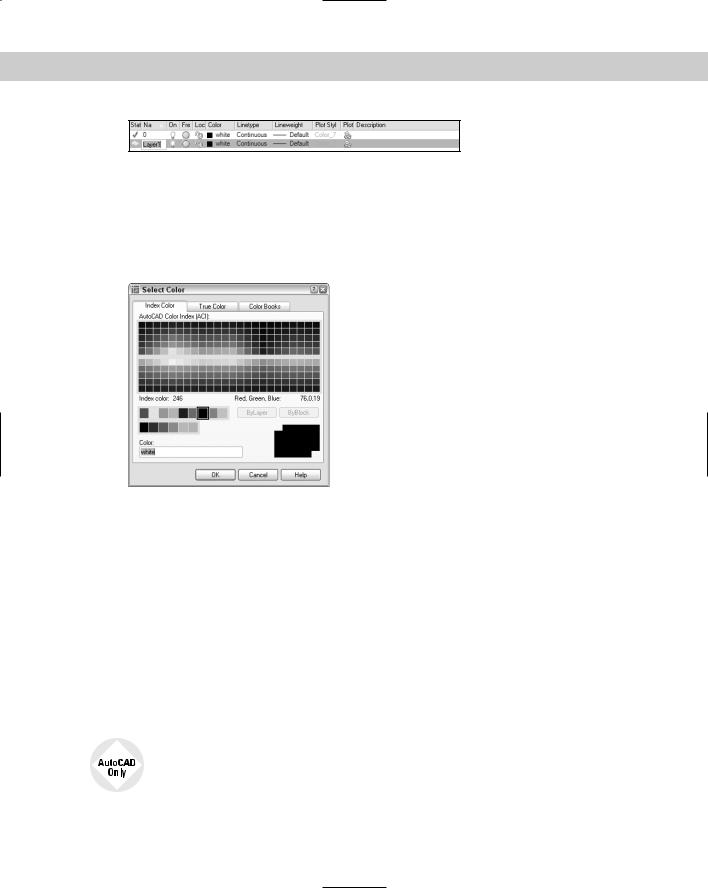
Click the New Layer icon. A new layer appears, named Layer1, as shown in Figure 11-2. |
|
The name is highlighted so that you can immediately type in a new name for the layer. |
|
Press Enter after you type the name. |
Tip |
To create several new layers at once, click New and type all the layer names you want, sepa- |
|
rated by commas. Press Enter after the last layer that you want. If you want a new layer to have |
|
the same color and/or linetype as an existing layer — which is very common — choose that |
|
existing layer and click New. The new layer inherits the properties of the selected layer. You |
|
can then make any changes you want. |
|
Layer names can be up to 255 characters long and may include spaces. Layer names retain the |
|
uppercase/lowercase characters that you type. Layer names may not include the following |
|
symbols: < > / \ " ; ? * | , `. |
Chapter 11 Organizing Drawings with Layers, Colors, Linetypes, and Lineweights |
241 |
Figure 11-2: The new layer appears as Layer1 and is highlighted so that you can enter the new layer name.
Assigning a color
To change the default color, move the cursor to the color box in the same row as the new layer. Click to open the Select Color dialog box, as shown in Figure 11-3 with the Index Color tab displayed. (The AutoCAD LT Select Color dialog box doesn’t have any other tabs.)
Figure 11-3: The Select Color dialog box.
Click the color that you want. At the bottom of the dialog box, the color’s name or number appears along with a sample of the color. Click OK to close the dialog box and return to the Layer Properties Manager.
Note that the Index Color tab offers you a choice of standard colors, gray shades, and a fuller palette of colors. The standard colors are the original colors that AutoCAD (and then AutoCAD LT) offered, and they’re the ones most often used, even today. Their advantage is that each color is easily distinguishable from the others. These colors have both a name and a number, whereas other colors have only a number (an index). The standard colors are red (1), yellow (2), green (3), cyan (4), blue (5), magenta (6), and white (7).
You have the choice of using many different colors for the background color of a drawing, but commonly it is a black or a white screen. The default screen is black and the default color for 7 is white. When you work on a white screen, the default color for 7 appears black, but it is still called white. Therefore, if you choose the black color tile in the Select Color dialog box, the color is listed as white. To change the screen color, choose Tools Options Display Colors.
AutoCAD offers two other tabs in the Select Color dialog box. The True Color tab lets you define any color and the Color Books tab lets you use special files that define colors.
242 Part II Drawing in Two Dimensions
Installing color books
You can install additional color books. Color book files must have an .acb file extension. In addition to Pantone color books, you may be able to find DIC or RAL color specification files.
The default location for color books is in the Support\Color subfolder of your AutoCAD 2005 program folder. If you copy color-book files there, you can find them on the Color Books tab of the Select Color dialog box. Another default location is in the Documents and Settings\username\ Application Data\AutoCAD 2005\R16.0\enu\Support\Color folder. You use this folder for color books that you install. To use color books from another location, follow these steps:
1.Choose Tools Options to open the Options dialog box.
2.Choose the Files tab.
3.Double-click the Color Book Locations item.
4.Click Add and then click Browse. Locate the color book file and click OK.
If you have the Select Color dialog box open while you copy a new color-book file to a location, close the dialog box and re-open it to access the new colors.
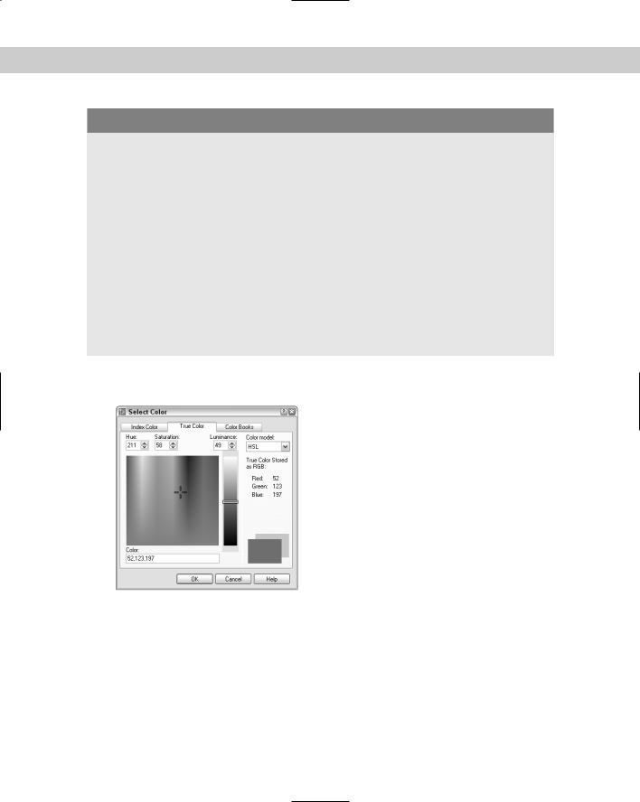
For more color choices, click the True Color tab, shown in Figure 11-4.
Figure 11-4: The True Color tab of the Select Color dialog box offers a more precise way to define color.
To define a color, first choose the color model from the Color Model drop-down list. You have two choices:
HSL (Hue, Saturation, Luminance): Hue is the actual wavelength of light that defines the color. Saturation is the purity or intensity of the color. Luminance is the brightness of the color.
RGB (Red, Green, Blue): Defines a color according to the intensity of red, green, and blue in the color.
Chapter 11 Organizing Drawings with Layers, Colors, Linetypes, and Lineweights |
243 |
If you choose the HSL color model, specify the color as follows:
1.Specify the hue by dragging the crosshairs horizontally across the colors or type a value from 0° to 360° in the Hue text box.
2.Specify the saturation by dragging the crosshairs vertically over the colors or type a value from 0% to 100% in the Saturation text box.
3.Specify the luminance by dragging the bar on the color slider or type a value from 0% to 100% in the Luminance text box.
Note When you define a color using the HSL color model, you also see the RGB values displayed in the Select Color dialog box.
If you choose the RGB color model, specify the red color by dragging the color bar or type a value from 1 to 255 in the Red text box. Do the same for the green and blue color values.
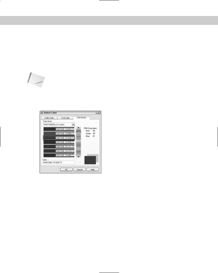
You can also choose a color using the Color Books tab, shown in Figure 11-5.
Figure 11-5: The Color Books tab of the Select
Color dialog box.
The Color Books tab of the Select Color dialog box displays colors in color books. Color books are files that define colors. AutoCAD includes several Pantone color books. Pantone is a commonly used system of matching colors often used for printing on paper and fabric.
To use a color from a color book, follow these steps:
1.On the Color Books tab of the Select Color dialog box, choose a color book from the Color Book drop-down list.
2.Drag the color slider or use the up and down arrows to choose a “page” of the color book. On the left, you see the colors for that page. A page can hold up to ten colors.
3.Choose one of the colors on the left side of the dialog box.
4.Click OK.

244 Part II Drawing in Two Dimensions
Assigning a linetype
The default linetype is a continuous line, but you can also use many other linetypes, which are repeating patterns of dashes and/or dots and spaces. Linetypes can also include text and shapes. Linetypes are covered more fully later in this chapter.
To change the default linetype, move the cursor to the linetype in the new layer’s row. Click to open the Select Linetype dialog box, as shown in Figure 11-6.
Figure 11-6: The Select Linetype dialog box as it appears before you have loaded any linetypes.
If the linetype that you want appears on the list, click the linetype and choose OK to close the dialog box. If the linetype does not appear, you need to load the linetype. Click Load to open the Load or Reload Linetypes dialog box, shown in Figure 11-7.
Linetypes are stored in text (or ASCII) files with the filename extension .lin. The standard linetypes are stored in acad.lin in AutoCAD and in aclt.lin in AutoCAD LT. You can create your own linetypes and store them in acad.lin or aclt.lin. You can also store them in another file that you create with the extension .lin. Click File at the top of the dialog box if you want to load a linetype from a file that you created. Choose the linetype that you want to load and click Open.
Figure 11-7: The Load or Reload Linetypes dialog box.
Chapter 11 Organizing Drawings with Layers, Colors, Linetypes, and Lineweights |
245 |
Cross- |
See Chapter 31 for a full discussion of creating your own linetypes. |
Reference |
|
To choose a range of linetypes to load, click the first linetype in the range, press Shift, and click the last linetype in the range. To choose more than one noncontiguous linetype, press Ctrl for each additional linetype you choose. To select all or clear all of the linetypes, rightclick in the dialog box and choose the desired option from the shortcut menu.
As soon as you load a linetype and click OK, you return to the Select Linetype dialog box. The loaded linetype now appears on the list. Choose it and click OK. You’re now back in the Layer Properties Manager dialog box.
Assigning a lineweight
A lineweight assigns a width to a line. When you give a layer a lineweight, every object on that layer has the same lineweight. A lineweight can help to distinguish various elements of your drawing, both on-screen and on paper. For example, you could use a thicker lineweight to indicate planned construction changes, for dimension lines, or to represent the true width of an object. The LWT button on the status bar turns on and off the display of lineweights. By default, LWT is off.
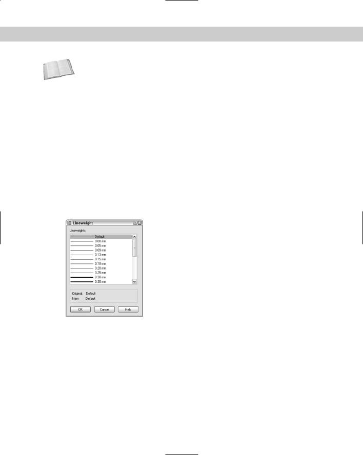
To set a lineweight for a layer, click the Lineweight column of that layer to open the Lineweight dialog box, shown in Figure 11-8. Choose a lineweight and click OK.
Figure 11-8: When you click the Lineweight column of the Layer Properties Manager, the Lineweight dialog box opens so that you can choose a lineweight.
Lineweights have the following features:
The default lineweight value for layers and objects is called DEFAULT, which has a value of 0.010 inch or 0.25 mm.
On the Model tab, where you draw, lineweights are displayed in relation to pixels, the unit of measurement for computer screens. A lineweight of 0 is displayed with a width of one pixel. Wider lineweights are calculated proportionally to the actual width of the lineweight. The lineweight display on the Model tab does not change as you zoom in or out.

246 Part II Drawing in Two Dimensions
On Layout tabs (covered in Chapter 17), lineweights are displayed in real-world units as they will be plotted. Lineweights act like other objects in your drawing and look bigger or smaller as you zoom in and out.
By default, lineweights are measured in millimeters. You can format lineweights by choosing Format Lineweight. The Lineweight Settings dialog box opens, shown in Figure 11-9. The Lineweights section lists available lineweights. Choose a default lineweight from the Default drop-down list. The default is 0.01 inch or 0.25 mm. The Adjust Display Scale slider determines how lineweights are displayed on the Model tab. Adjust this setting if you use several closely related lineweights but can’t distinguish them on your screen. The Display Lineweight check box turns the display of lineweights on and off. (See the next bullet for an easier way to do this.)
You can turn the display of lineweights on and off — just click the LWT button on the status bar.
If you don’t want to use lineweights, you can just ignore them and display every object using the default lineweight.
Figure 11-9: The Lineweight Settings dialog box lets you format how lineweights are measured and displayed.
After you’ve set your new layer’s color, linetype, and lineweight in the Layer Property Manager, you’re ready to use the layer. You can click Apply after any change to apply the change without closing the dialog box. Click OK to close the Layer Properties Manager.
On the |
The drawing used in the following Step-by-Step exercise on creating layers, ab11-a.dwg, is |
CD-ROM |
in the Drawings folder on the CD-ROM. |
STEP-BY-STEP: Creating a New Layer
1.Open ab11-a.dwg from the CD-ROM.
2.Save the file as ab11-01.dwg in your AutoCAD Bible folder.
3.Choose Layer Properties Manager from the Layers toolbar to open the Layer Properties Manager.
4.Click the New Layer icon. A new layer named Layer1 appears, highlighted. Type Walls as the name for the new layer.
Chapter 11 Organizing Drawings with Layers, Colors, Linetypes, and Lineweights |
247 |
5.Click the color square in the Color column to open the Select Color dialog box. Choose the blue square from the Standard Colors and click OK.
6.Choose the New Layer icon again to create another new layer. Type Hidden .
7.Click the color square in the Color column to open the Select Color dialog box.
8.If you have AutoCAD, do the following:
In the Select Color dialog box, click the True Color tab. From the Color Model drop-down list, choose RGB. In the Color text box, type 141, 218, 189. Press Tab. You should see a teal (blue-green) color. Click OK.
If you have AutoCAD LT, do the following:
Find Index Color 121 (a teal color) and click. Then click OK.
9.In the main layer listing, click Continuous in the same row as the Hidden layer to open the Select Linetype dialog box. Click Load to open the Load or Reload Linetypes dialog box. Scroll down until you see the HIDDEN linetype. Choose it and click OK. In the Select Linetype dialog box, choose HIDDEN and click OK.
10.Click the Description column for the Hidden layer. Click again so that a text cursor appears. Type teal, hidden lines .
11.Click OK to close the Layer Properties Manager.
12.Click the Layer Control drop-down box on the Layers toolbar to see the two layers you just created listed there. Click again to close the box.
13.Save your drawing.
Using layers
To use a layer you have just created, click the Set Current icon in the Layer Properties Manager or double-click the layer’s name. Then click OK to return to your drawing.
Objects you create now are drawn on that layer and display with the layer’s color, linetype, and lineweight. (The lineweight only shows if the LWT button on the status bar is on.)
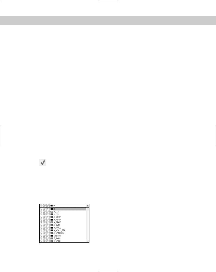
All objects that you draw go on the current layer. After you have the layers you need, you need to switch from layer to layer as you draw. You can continue to choose Layers in the Layer Properties Manager, click the name of a layer, click Set Current, and then click OK. But there is an easier way — the Layer Control drop-down list on the Layers toolbar, shown in Figure 11-10.
Figure 11-10: The Layer Control drop-down list.
248 Part II Drawing in Two Dimensions
The Layer Control drop-down list has two display modes:
If no object is selected, it displays the current layer.
If one or more objects are selected, it displays the layer of the selected object(s).
To check the current layer, make sure no object is selected. If necessary, press Esc to deselect any objects.
Note |
When objects on varying layers are selected, the Layer Control list goes blank, indicating that |
|
more than one layer is included in the selection. |
To open the Layer Control drop-down list, click its arrow. You see a list of all your layers, including their states and colors. Pass the mouse over the items, and a tooltip tells you what they mean. The Layer Control drop-down list has three functions:
It switches the current layer so that you can draw on a new layer.
It changes the following states of any specific layer on the list:
•On/Off
•Frozen/Thawed
•Frozen in Current Viewport/Thawed in Current Viewport
•Locked/Unlocked
It changes the layer of a selected object.
Take the time to learn how to use this drop-down list; it can save you a great deal of time. To change other states of a layer (such as plottable/not plottable), click Layers Properties Manager on the Layers toolbar to open the Layer Properties Manager.
Switching the current layer
To switch the current layer, make sure that no object is currently selected, click the Layer Control drop-down list arrow and click the name of the layer that you want to be current. Be careful to click only the name — otherwise, you may change the layer’s state. You may need to press Esc first to deselect all objects. After you click a new layer name, the drop-down list automatically closes.
The Layer Previous button on the Layers toolbar switches you to the last layer you used. Click it another time and you’re in the layer before that. Use Layer Previous as a shortcut
to finding and choosing the last layer you used on the Layer Control drop-down list.
Changing a layer’s state
After you create a layer, you can manage that layer — and all the objects on that layer — by changing its states. You can change some layer states through the Layer Control drop-down list; others must be changed in the Layer Properties Manager. The layer states each have different properties and uses:
On/Off: Turn layers off when objects on those layers interfere with the drawing process. For example, if you want to edit only objects on your Object layer, but objects exist on other layers nearby, you can turn off the other layers and easily select the objects on the Object layer with a window. Then turn the other layers back on. The on/off state is available on the Layer Control drop-down list.

Chapter 11 Organizing Drawings with Layers, Colors, Linetypes, and Lineweights |
249 |
Thaw/Freeze: You can freeze layers for reasons similar to those that lead you to turn off layers. In general, freeze layers when you want to work without those layers for a longer period of time. The thawed/frozen state is available on the Layer Control dropdown list.
Thaw/Freeze in Current Viewport: You may want to freeze or thaw layers in some floating viewports but not in others. For example, you may want to display dimensions in one viewport but not in others; to do so, freeze your dimensions layer in all the viewports except one. You can change this state on the Layer Control drop-down list if you’re working on a layout. You can also click the Current Viewport Freeze icon in the Layer Properties Manager.
Thaw/Freeze in New Viewports: You can also freeze or thaw layers in future viewports that you create. For example, after you display dimensions or text in one viewport, you may want to make sure they won’t appear in any new viewports that you create. This state is available in the New Viewport Freeze column of the Layer Properties Manager.
Cross- |
See Chapter 17 for an explanation of floating viewports and layouts. |
Reference |
|
Unlock/Lock: Lock a layer when you want to ensure that objects on that layer are not changed. You can still use objects on locked layers for reference (for example, you can use their object snaps). Click the lock/unlock icon on the Layer Control drop-down list.
Plot/No Plot: Make a layer not plottable when you want to create reference text or revision marks on your drawing but don’t want to plot them. Another example: If you have a drawing that contains both actual and planned structures, you could plot showing only the actual structures. Being able to change a layer’s plottable state makes it possible for you to create variations on your drawing, perhaps for different users, such as electricians, plumbers, and roofers. The plot/no plot state is available in the Plot column of the Layer Properties Manager.
Tip |
Both the off and frozen states make layers invisible. The purpose of frozen and thawed layer |
|
states is to reduce regeneration time — and that’s the main difference between On/Off and |
|
Thawed/Frozen layer visibility options. However, today’s computers are faster, and recent |
|
releases of the software have reduced the need for regeneration. Also, remember that thaw- |
|
ing a layer causes a regeneration, whereas turning a layer back on only causes a redraw. As |
|
a result, you might actually save a regeneration by using On/Off instead of Thawed/Frozen. |
|
Click any of the state icons to toggle a layer’s state. For example, if you want to freeze a layer, |
|
click its sun and it switches to a snowflake. Table 11-2 shows the icons for each state. |
Table 11-2: Layer State Icons
State |
Icon |
State |
Icon |
|
|
|
|
On |
|
Off |
|
Thawed (in all viewports) |
|
Frozen (in all viewports) |
|
Thawed (in current viewport) |
|
Frozen (in current viewport) |
|
Continued
250 Part II Drawing in Two Dimensions
Table 11-2 (continued)
State |
Icon |
State |
Icon |
|
|
|
|
Thawed (in new viewports) |
|
Frozen (in new viewports) |
|
Unlocked |
|
Locked |
|
Plottable |
|
Not plottable |
|
|
|
|
|
When you change a layer’s state, the drop-down list stays open so that you can change the state of more than one layer at a time. Click the top of the list to close it.
Caution |
Be careful when editing a drawing with frozen or off layers — it’s easy to forget about them. For |
|
example, you could move a whole section of your drawing and inadvertently leave the frozen |
|
objects in that section behind. |
Saving layer states
Often you work with sets of layer states. For example, you may lock certain layers during part of the editing process to avoid changing objects on those layers. You may also set some layers as not plottable just before final plotting but want them plotted for a draft plot. You may also want to temporarily change the properties of certain layers — color, linetype, lineweight, and plot style — and then change them back.
You could spend a lot of time adjusting all these layer states and properties over and over. Instead, you can save and restore sets of layer states — the properties and states of all the layers in a drawing. You can save layer states to automate the process of restoring layer states and properties by saving the set of all layer states and properties. After you save this set, you can restore it at any time. The term layer states includes the set of all layer states as well as their properties.
You can also export layer-state settings to a file. You can then use the layer-state settings in another drawing with the same or similar layers.
To save a layer state, follow these steps:
1.Set all the layer states and properties the way you want them. Usually, you’ve already done this and should save the state before making changes that you plan to reverse later on.
2.Choose Layer Properties Manager from the Layers toolbar.
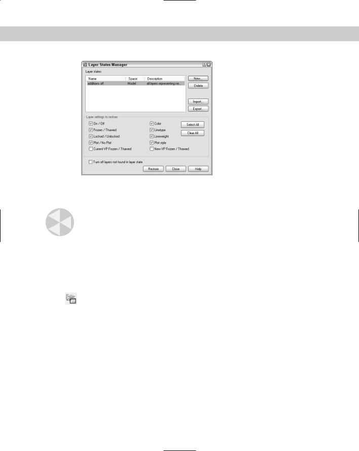
3.In the Layer Properties Manager, click the Layer States Manager icon to open the Layer States Manager dialog box, shown in Figure 11-11.
4.Click New and type a name for your layer state in the New Layer State Name text box of the New Layer State to Save dialog box. If you want, type a description. Click OK.
Chapter 11 Organizing Drawings with Layers, Colors, Linetypes, and Lineweights |
251 |
Figure 11-11: The Layer States Manager dialog box.
5.Back in the Layer States Manager, choose which of the layer states and properties you want to save in the Layer Settings to Restore section.
Caution |
States and properties that you do not save are not affected later when you restore the layer |
|
state. For example, if you save only the on/off state and then change both a layer’s on/off state |
|
and its color, when you restore the layer state, only the on/off state is returned to its original |
|
setting; the layer retains its new color. |
6.If you want your drawing to look exactly as it did when you saved the layer state (in terms of layers), check the Turn Off Layers Not Found in Layer State check box. Any new layers that you create after saving the layer state are then turned off when you restore your layer state.
7.Click OK.
To restore a layer state, open the Layer Properties Manager and click the Layer States Manager button to open the Layer States Manager. Choose the layer state and click
Restore. Then click OK to close the Layer Properties Manager.
The Layer States Manager enables you to manage layer states in the following ways:
Restore: Restores a saved layer state.
Delete: Deletes the layer state.
Import: Imports a layer state that has been previously exported as a .las file. Importing a layer state gives you access to layer states that others have saved.
Export: Saves the settings of a layer state in a .las file. Exporting a layer state gives others access to your layer state settings.
You can also change the properties and states that you save by checking or unchecking any of the check boxes at the bottom of the Layer States Manager. To rename a layer state, click its name, type a new name, and press Enter. After you finish using the Layer States Manager, click Close to close the dialog box.

252 Part II Drawing in Two Dimensions
The Express Tools contains many layer-related tools that you can add to your arsenal. Many of these layer tools can save you considerable time over the course of creating a drawing. Table 11-3 explains them briefly. See Appendix A for information on installing Express Tools.
Table 11-3: Express Tools Layer Commands
Layer Name |
Menu Description |
|
|
|
|
LAYWALK |
Express Layers Layer Walk |
A full-featured command that helps you see |
|
|
which objects are on which layers. You can |
|
|
list the number of objects on each layer, |
|
|
count the total number of layers, save layer |
|
|
states, and purge unused layers, using the |
|
|
dialog box and the shortcut menu. |
LAYMCH |
Express Layers Layer Match |
Changes the layer of selected objects to |
|
|
match that of a selected object. |
LAYCUR |
Express Layers |
Changes the selected object’s layer to the |
|
Change to Current Layer |
current layer. |
COPYTOLAYER |
Express Layers |
Copies objects while changing the copy to |
|
Copy Objects to New Layer |
the layer you specify. |
LAYISO |
Express Layers Layer Isolate |
Turns off all layers except the layer of an |
|
|
object you select, so that you can isolate a |
|
|
specific layer. |
LAYVPI |
Isolate Layer to Current Viewport |
Freezes all layers except the layer of an |
|
|
object you select in all viewports except the |
|
|
current one, isolating the selected layer in |
|
|
the current viewport. |
LAYOFF |
Express Layers Layer Off |
Turns the layer of the selected object(s) off. |
LAYON |
Express Layers Turn All Layers On |
Turns all layers on. |
LAYFRZ |
Express Layers Layer Freeze |
Freezes the layer of the selected object(s). |
LAYTHW |
Express Layers Thaw All Layers |
Thaws all layers. |
LAYLCK |
Express Layers Layer Lock |
Locks the layer of the selected object(s). |
LAYULK |
Express Layers Layer Unlock |
Unlocks all layers. |
LAYMRG |
Express Layers Layer Merge |
Changes the layer of all objects on the first |
|
|
layer selected to the second layer selected. |
|
|
The first layer is purged. |
LAYDEL |
Express Layers Layer Delete |
Deletes objects from the specified layer and |
|
|
purges that layer. |
|
|
|
Chapter 11 Organizing Drawings with Layers, Colors, Linetypes, and Lineweights |
253 |
Changing an existing object’s layer
Sometimes you need to change the layer of an object or objects you’ve already drawn. You can do this easily by selecting one or more objects and clicking the layer name that you want for the object in the Layer Control drop-down list. The list automatically closes.
Note |
If you turn off Noun/verb selection, as I explain in “Customizing the selection process” in Chap- |
|
ter 9, you cannot select an object and change its layer from the Layer Control drop-down list. |
|
Instead, you can change the layer in the Properties palette. |
You can also change an object’s layer in the Properties palette. Choose Properties on the Standard toolbar. Use the Properties palette if you want to change more than one property of an object at one time.
Caution |
It’s easy to inadvertently change an object’s layer. Make sure objects are not selected (press |
|
Esc) if you’re about to use the Layer Control drop-down box just to change the current layer. |
Making an object’s layer current
If you’re adding an object, you usually want to draw on the same layer as an existing object. You could select the object to see what layer it’s on, press Esc to deselect the
object, and then choose that layer from the Layer Control drop-down list to make it current. However, this process is easier with the Make Object’s Layer Current button on the Layers toolbar. Simply select an object and click the button. That object’s layer is now current.
On the |
The drawing used in the following Step-by-Step exercise on working with layers, ab11- |
CD-ROM |
b.dwg, is in the Drawings folder on the CD-ROM. |
STEP-BY-STEP: Working with Layers
1.Open ab11-b.dwg from the CD-ROM.
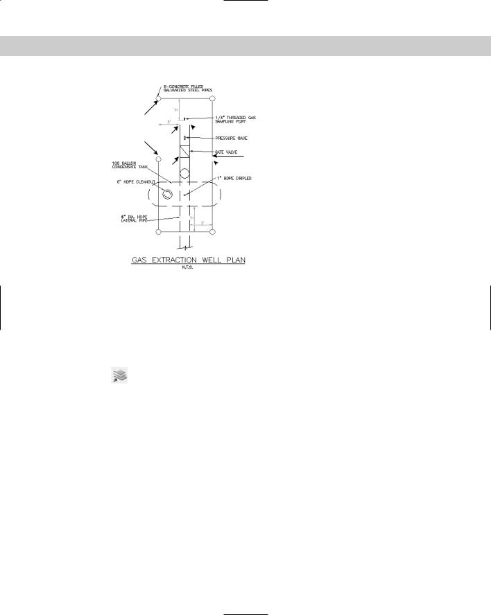
2.Save the file as ab11-02.dwg in your AutoCAD Bible folder. This drawing is shown in Figure 11-12. The current layer is 0. Make sure OSNAP is on. Set running object snaps for endpoint and quadrant.
3.Click the Layer Control drop-down list and click Pipes to change the current layer to Pipes.
4.Start the LINE command. Draw a line from 1 to 2 in Figure 11-12, using the Quadrant running object snap.
5.Click the Layer Control drop-down list and click Object to change the current layer to Object.
6.Click the Layer Control drop-down list and click the On/Off icon of the Dim layer. Click again at the top of the list to close it.
7.Start the CIRCLE command. Right-click and choose 2p to use the two-point option. Draw a circle from the endpoint of 3 to 4 in Figure 11-12 using the Endpoint running object snap.
8.Without changing the layer, start the CIRCLE command and again use the 2p option. Draw a circle between the endpoints at 5 and 6.
254 Part II Drawing in Two Dimensions
2
1 3
 4
4
 7
7
5
8  6
6
Figure 11-12: This gas extraction well plan drawing needs to be completed.
Thanks to the Army Corps of Engineers for this drawing.
9.The last circle was drawn on the wrong layer. To change its layer, select the circle. Then click the Layer Control drop-down list and choose Pipes. Press Esc to remove the grips and see the result. The circle is now on the Pipes layer. Notice that the current layer is still Object in the Layer Control display.
10.Pick any red object (the Pipes layer). Choose Make Object’s Layer Current from the Layers toolbar. The Pipes layer is now the current layer. Draw a line from the right
quadrant of the circle at 1 to the left quadrant of the circle at 5 and 6 in Figure 11-12.
11. You want to draw a line on the Object layer.
•If you have AutoCAD: Because that is the previous layer you used, click Layer Previous on the Layers toolbar. The Object layer is now the current layer.
•If you have AutoCAD LT: Choose the Object layer from the Layer Control dropdown list.
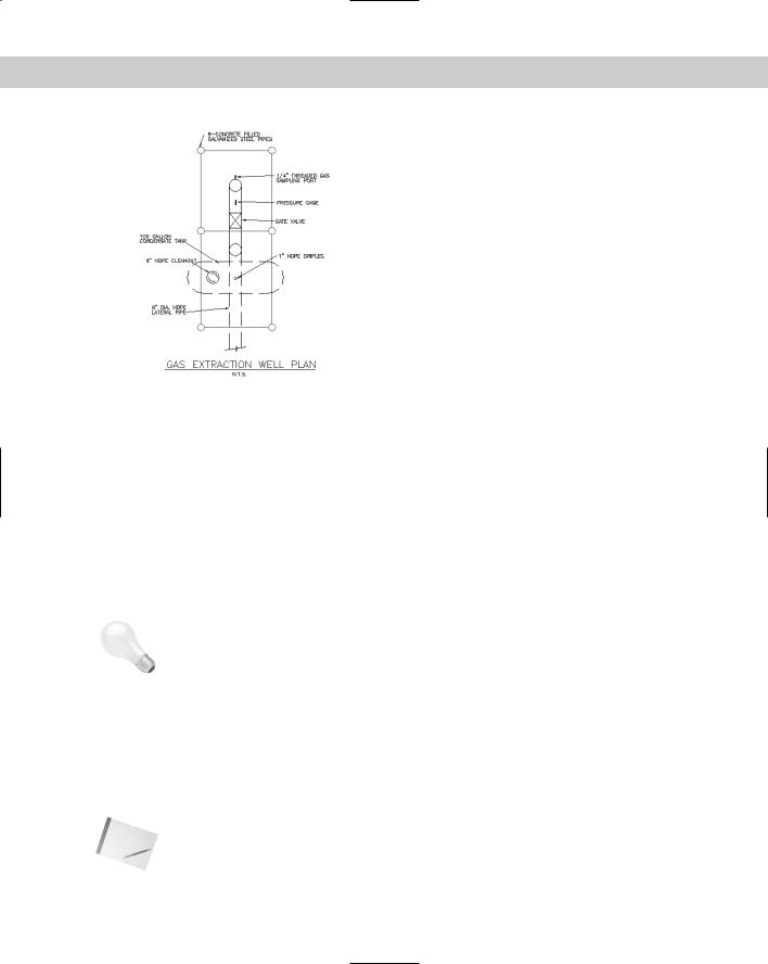
12.Draw a line from the endpoint at 7 to the endpoint at 8.
13.Pick any text to see what layer it is on. The Layer Control drop-down box changes to
show the Text layer. Press Esc to deselect the text. Now choose the words GAS EXTRAC- TION WELL PLAN at the bottom of the drawing. Click the Layer Control drop-down box and choose Text. Press Esc to remove the grips.
14. Save your drawing. It should look like Figure 11-13.
Later in this chapter, I explain how to import layers from other drawings and translate layers from one drawing to another.
Chapter 11 Organizing Drawings with Layers, Colors, Linetypes, and Lineweights |
255 |
Figure 11-13: The completed drawing.
|
Modifying layers |
|
Sometimes you need to change the properties of a layer, such as its color or linetype. Changing |
|
a layer’s properties is a powerful tool because every object on that layer is automatically regen- |
|
erated with the new properties. Other layer housekeeping tasks are renaming and deleting lay- |
|
ers. You use the Layer Properties Manager for these functions. |
|
Sorting columns |
|
If you have many layers in a drawing, sorting can help you find the layers you need to work |
|
on. You can sort the layer listing in a drawing by any column, by clicking once on the column |
|
title. Click again to see the list in reverse order. Long layer names display a tooltip with the |
|
entire layer name. |
Tip |
If sorting by layer name does not appear to be working, increase the value for the MAXSORT |
|
system variable, which determines the maximum number of symbols that AutoCAD or |
|
AutoCAD LT sorts. Type maxsort on the command line and enter a larger number. Press |
|
Enter. |
|
Filtering the layer list |
|
Some complex drawings may have dozens of layers and you may have a hard time finding the |
|
layer that you want to change in the Layer Properties Manager. You can filter the layer list so |
|
that you only see the layers you want. This makes it easy to change a group of layers at once. |
|
The filter tree panel on the left side of the Layer Properties Manager contains one filter, All |
|
Used Layers, as well as the default that displays all layers. To display only used layers, click |
|
the All Used Layers filter in the filter tree panel. |
Note If you don’t see the filter tree panel, right-click in the Layer Properties Manager and choose Show Filter Tree.
256 Part II Drawing in Two Dimensions
You can create your own filters. There are two types of filters:
Properties filter: Defines a filter by the properties of the layer. For example, you can create a filter that displays only green layers or layers that start with the letter A.
Group filter: Defines a filter by selecting layers that go into a filter. A group filter offers complete flexibility to filter layers. For example, you might want to create a group filter that contains all your text, annotation, and dimension layers.
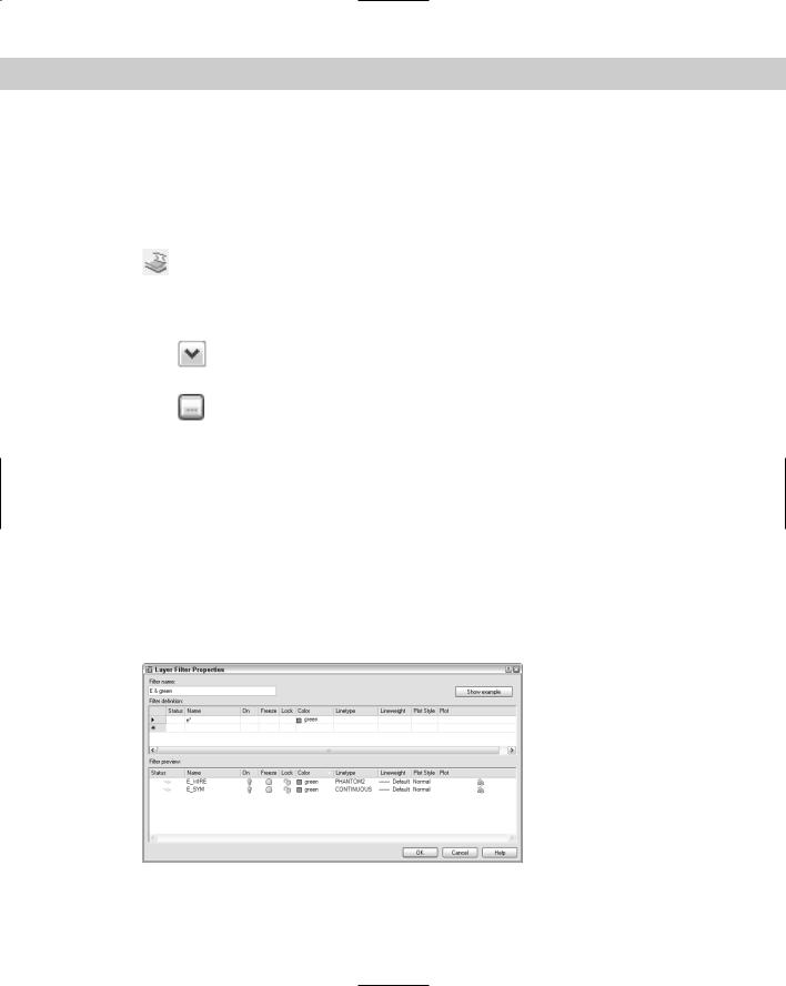
To create a properties filter, click the New Property Filter button to open the Layer Filter Properties, shown in Figure 11-14. Notice that the Filter Definition pane at the top has
the same columns as the Layer Properties Manager.
Name the filter in the Filter Name text box. To choose a property, click in that property’s column. Then do one of the following:
If a drop-down arrow appears, click the arrow and choose one of the options from the drop-down list. (To remove a property, choose the blank line at the top of the
drop-down list.)
If an ellipsis button appears, click the button and choose a property from the dia-
log box that opens. For example, you can choose a layer color from the Select Color dialog box. (To remove a property, select the text, press Del, and click anywhere outside the column.)
To specify a filter for a named property, such as the name or linetype of a layer, you can use wildcards. The two most common wildcard characters are * (asterisk), which replaces any number of characters, and ?, which replaces any single character. Figure 11-14 shows the layer name filter set to e*. The color is also specified as green. Therefore, the filter includes only layers whose names start with the letter E and are green.
As you work, the Filter Preview pane shows the results of your filter. When you’re done, click OK. The Layer Properties Manager shows only the layers that match your filter specifications.
To display all layers except the ones specified by the filter, click Invert Filter. If you want to filter the Layer Control listing on the Layers toolbar in the same way, check Apply to Layers toolbar. Click OK to close the Layer Properties Manager and return to your drawing.
Figure 11-14: The Layer Filter Properties dialog box.
Chapter 11 Organizing Drawings with Layers, Colors, Linetypes, and Lineweights |
257 |
Tip When you work with a large number of layers, think carefully about how you name them. Naming layers in groups is common. For example, if you have several text layers, you could name them Text Title, Text Notes, and Text Schedule. A systematic layer-naming scheme makes it easy to filter the layers you need, which in turn makes it easy to make changes to groups of layers.
Changing a layer’s color, linetype, and lineweight
To change a layer’s color, choose Layer Properties Manager from the Layers toolbar to open the Layer Properties Manager. Choose the color swatch of the layer that you want
|
to modify. The Select Color dialog box opens. Choose a color and click OK twice to return to |
|
your drawing. For more information about choosing colors, see “Assigning a color” earlier in |
|
this chapter. |
|
To change a layer’s linetype, follow the same procedure as for changing the color. If you need to |
|
choose a linetype that is not on the list, click the linetype of the layer to open the Select Line- |
|
type dialog box. There you can either choose a loaded linetype or load a linetype if necessary. |
|
To change a layer’s lineweight, open the Layer Properties Manager and click the lineweight |
|
for any layer. Choose a new lineweight from the Lineweight dialog box. |
Tip |
You can modify more than one layer at a time. In the Layer Properties Manager, right-click |
|
and choose Select All to choose all the layers. Choose Clear All to deselect all layers. You can |
|
choose a range of layers by clicking the first in the range, pressing Shift, and clicking the last |
|
in the range. Finally, you can choose individual layers by pressing Ctrl for each additional |
|
layer. Changes you make to color, linetype, or lineweight affect all the selected layers. |
|
Renaming layers |
|
Thinking out your layer naming scheme in advance is best. Many disciplines and organiza- |
|
tions have layer naming standards. However, sometimes you simply need to rename a layer. |
|
To rename a layer, choose Layer Properties Manager from the Layers toolbar to open the |
|
Layer Properties Manager. Click the name of the layer, and then click a second time. A border |
|
appears, and the name is highlighted. Type the new name and press Enter. |
Note |
You cannot rename layer 0. Layer 0 is the default layer and always remains the same. |
Deleting layers
To delete a layer, choose Layer Properties Manager from the Layers toolbar to open the Layer Properties Manager. Click the name of the layer. Choose Delete and click OK.
Note You cannot delete the current layer or any layer that has objects on it. (Where would those objects go?) You also cannot delete layer 0, which is the default layer. Finally, you cannot delete layers from external references (covered in Chapter 19).
Purging layers and linetypes
Layer and linetype definitions add to the size of your drawing because they’re kept in the drawing’s database. Therefore, eliminating layers and linetypes that you aren’t using is worthwhile. You can delete them, but sometimes it’s hard to know which layers contain no objects. The PURGE command lets you delete many types of unused definitions, including layers and linetypes.

258 Part II Drawing in Two Dimensions
To purge layers and linetypes, choose File Drawing Utilities Purge. The Purge dialog box opens, shown in Figure 11-15.
|
Figure 11-15: The Purge dialog box. |
Note |
The Incremental Save Percentage option may prevent a purge during a drawing session from |
|
removing all unreferenced layers or linetypes from the drawing. To avoid this, you can either |
|
set incremental save to zero or save the drawing and reopen it and then immediately use the |
|
PURGE command. To set this option, choose Tools Options Open and Save tab. |
|
At the top of the dialog box, you can choose to view objects that you can purge or objects that |
|
you cannot purge. Why would you want to view objects that you cannot purge? Sometimes it’s |
|
hard to figure out why you can’t purge a certain object, and the dialog box has a handy feature |
|
that lets you select an object and view possible reasons why it cannot be purged. |
|
To start purging, choose View Items You Can Purge. A plus sign (+) next to each type of object |
|
indicates that it contains purgeable objects. For example, Figure 11-15 indicates that you can |
|
purge blocks, dimension styles, layers, and shapes. Click the plus sign to display the specific |
|
items. |
|
To purge an individual item, select it and click Purge. Check Confirm Each Item to Be Purged if |
|
you want to see a dialog box asking you to confirm each purge. Click Purge All to purge all |
|
possible items. Check Purge Nested Items to purge items within other named objects. Usually, |
|
these are layers, linetypes, and so on inside blocks. |
Tip |
You can select more than one item at a time to purge. To select an additional item, press Ctrl |
|
as you click. To select a contiguous group of items, click the first item, press and hold Shift, |
|
and select the last item in the group. |
After you’re done purging, click Close to close the Purge dialog box.

Chapter 11 Organizing Drawings with Layers, Colors, Linetypes, and Lineweights |
259 |
On the |
The drawing used in the following Step-by-Step exercise on modifying layers, ab11-c.dwg, |
CD-ROM |
is in the Drawings folder on the CD-ROM. (Thanks to Michael J. Lemmons of Winston |
|
Products Company in Louisville, Kentucky, for this drawing.) |
STEP-BY-STEP: Modifying Layers
1.Open ab11-c.dwg from the CD-ROM.
2.Save the file as ab11-03.dwg in your AutoCAD Bible folder.
3. Choose Layer Properties Manager from the Layers toolbar.
4.Click the New Property Filter button.. In the Filter Name text box, type M layers. In the Name column, type m* (the asterisk is already there, so just type m before
the asterisk) to list all layers starting with the letter M. Click OK. The layer list now looks like Figure 11-16.
5.In the Layer Properties Manager, click the top layer. Press Shift and click the next-to- last layer. All the layers except for Mydims are selected. Click anywhere in the Linetype column to open the Select Linetype dialog box and choose Dashed. Click OK. Notice that all the selected layers now have a dashed linetype. Click OK to return to the drawing. The layers you selected now have the dashed linetype.
Figure 11-16: The Layer Properties Manager now shows only layers starting with the letter M.
6.Choose Layer Properties Manager from the Layers toolbar to open the Layer Properties
Manager again. Choose Mydims. Click it a second time so that a the name of the layer is highlighted. Type Titles . The name of the layer is changed. Click OK.
7.Start the ERASE command and pick anywhere on the title block (it is all one object) and the three labels FRONT, TOP, and RIGHT SIDE. Press Enter to end the command.
8.Choose Layer Properties Manager from the Layers toolbar again. Notice that the Titles layer is not on the list because this layer no longer starts with the letter M. In the Filter Tree panel, click All to display all the layers.
9.Scroll down the list of layers and choose Titles. You can see that its Status icon is off, indicating that the layer contains no objects. Click the Delete button. Click OK
to close the dialog box.
10. Save your drawing.