

- •Foreword
- •Preface
- •Is This Book for You?
- •How This Book Is Organized
- •How to Use This Book
- •Doing the Exercises
- •Conventions Used in This Book
- •What the Icons Mean
- •About the CD-ROM
- •Other Information
- •Contacting the Author
- •Acknowledgments
- •Contents at a Glance
- •Contents
- •Getting Acquainted with AutoCAD and AutoCAD LT
- •Starting AutoCAD and AutoCAD LT
- •Creating a New Drawing
- •Using the AutoCAD and AutoCAD LT Interface
- •Creating Your First Drawing
- •Saving a Drawing
- •Summary
- •Creating a New Drawing from a Template
- •Working with Templates
- •Opening a Drawing with Default Settings
- •Opening an Existing Drawing
- •Using an Existing Drawing as a Prototype
- •Saving a Drawing Under a New Name
- •Summary
- •The Command Line
- •Command Techniques
- •Of Mice and Pucks
- •Getting Help
- •Summary
- •Typing Coordinates
- •Displaying Coordinates
- •Picking Coordinates on the Screen
- •Locating Points
- •Summary
- •Unit Types
- •Drawing Limits
- •Understanding Scales
- •Inserting a Title Block
- •Common Setup Options
- •The MVSETUP Command
- •Summary
- •Using the LINE Command
- •Drawing Rectangles
- •Drawing Polygons
- •Creating Construction Lines
- •Creating Rays
- •Summary
- •Drawing Circles
- •Drawing Arcs
- •Creating Ellipses and Elliptical Arcs
- •Making Donuts
- •Placing Points
- •Summary
- •Panning
- •The ZOOM Command
- •Aerial View
- •Named Views
- •Tiled Viewports
- •Snap Rotation
- •User Coordinate Systems
- •Isometric Drawing
- •Summary
- •Editing a Drawing
- •Selecting Objects
- •Summary
- •Copying and Moving Objects
- •Using Construction Commands
- •Creating a Revision Cloud
- •Hiding Objects with a Wipeout
- •Double-Clicking to Edit Objects
- •Grips
- •Editing with the Properties Palette
- •Selection Filters
- •Groups
- •Summary
- •Working with Layers
- •Changing Object Color, Linetype, and Lineweight
- •Working with Linetype Scales
- •Importing Layers and Linetypes from Other Drawings
- •Matching Properties
- •Summary
- •Drawing-Level Information
- •Object-Level Information
- •Measurement Commands
- •AutoCAD’s Calculator
- •Summary
- •Creating Single-Line Text
- •Understanding Text Styles
- •Creating Multiline Text
- •Creating Tables
- •Inserting Fields
- •Managing Text
- •Finding Text in Your Drawing
- •Checking Your Spelling
- •Summary
- •Working with Dimensions
- •Drawing Linear Dimensions
- •Drawing Aligned Dimensions
- •Creating Baseline and Continued Dimensions
- •Dimensioning Arcs and Circles
- •Dimensioning Angles
- •Creating Ordinate Dimensions
- •Drawing Leaders
- •Using Quick Dimension
- •Editing Dimensions
- •Summary
- •Understanding Dimension Styles
- •Defining a New Dimension Style
- •Changing Dimension Styles
- •Creating Geometric Tolerances
- •Summary
- •Creating and Editing Polylines
- •Drawing and Editing Splines
- •Creating Regions
- •Creating Boundaries
- •Creating Hatches
- •Creating and Editing Multilines
- •Creating Dlines
- •Using the SKETCH Command
- •Digitizing Drawings with the TABLET Command
- •Summary
- •Preparing a Drawing for Plotting or Printing
- •Creating a Layout in Paper Space
- •Working with Plot Styles
- •Plotting a Drawing
- •Summary
- •Combining Objects into Blocks
- •Inserting Blocks and Files into Drawings
- •Managing Blocks
- •Using Windows Features
- •Working with Attributes
- •Summary
- •Understanding External References
- •Editing an Xref within Your Drawing
- •Controlling Xref Display
- •Managing Xrefs
- •Summary
- •Preparing for Database Connectivity
- •Connecting to Your Database
- •Linking Data to Drawing Objects
- •Creating Labels
- •Querying with the Query Editor
- •Working with Query Files
- •Summary
- •Working with 3D Coordinates
- •Using Elevation and Thickness
- •Working with the User Coordinate System
- •Summary
- •Working with the Standard Viewpoints
- •Using DDVPOINT
- •Working with the Tripod and Compass
- •Getting a Quick Plan View
- •Shading Your Drawing
- •Using 3D Orbit
- •Using Tiled Viewports
- •Defining a Perspective View
- •Laying Out 3D Drawings
- •Summary
- •Drawing Surfaces with 3DFACE
- •Drawing Surfaces with PFACE
- •Creating Polygon Meshes with 3DMESH
- •Drawing Standard 3D Shapes
- •Drawing a Revolved Surface
- •Drawing an Extruded Surface
- •Drawing Ruled Surfaces
- •Drawing Edge Surfaces
- •Summary
- •Drawing Standard Shapes
- •Creating Extruded Solids
- •Drawing Revolved Solids
- •Creating Complex Solids
- •Sectioning and Slicing Solids
- •Using Editing Commands in 3D
- •Editing Solids
- •Listing Solid Properties
- •Summary
- •Understanding Rendering
- •Creating Lights
- •Creating Scenes
- •Working with Materials
- •Using Backgrounds
- •Doing the Final Render
- •Summary
- •Accessing Drawing Components with the DesignCenter
- •Accessing Drawing Content with Tool Palettes
- •Setting Standards for Drawings
- •Organizing Your Drawings
- •Working with Sheet Sets
- •Maintaining Security
- •Keeping Track of Referenced Files
- •Handling Errors and Crashes
- •Managing Drawings from Prior Releases
- •Summary
- •Importing and Exporting Other File Formats
- •Working with Raster Images
- •Pasting, Linking, and Embedding Objects
- •Summary
- •Sending Drawings
- •Opening Drawings from the Web
- •Creating Object Hyperlinks
- •Publishing Drawings
- •Summary
- •Working with Customizable Files
- •Creating Keyboard Shortcuts for Commands
- •Customizing Toolbars
- •Customizing Tool Palettes
- •Summary
- •Creating Macros with Script Files
- •Creating Slide Shows
- •Creating Slide Libraries
- •Summary
- •Creating Linetypes
- •Creating Hatch Patterns
- •Summary
- •Creating Shapes
- •Creating Fonts
- •Summary
- •Working with Menu Files
- •Customizing a Menu
- •Summary
- •Introducing Visual LISP
- •Getting Help in Visual LISP
- •Working with AutoLISP Expressions
- •Using AutoLISP on the Command Line
- •Creating AutoLISP Files
- •Summary
- •Creating Variables
- •Working with AutoCAD Commands
- •Working with Lists
- •Setting Conditions
- •Managing Drawing Objects
- •Getting Input from the User
- •Putting on the Finishing Touches
- •Summary
- •Understanding Local and Global Variables
- •Working with Visual LISP ActiveX Functions
- •Debugging Code
- •Summary
- •Starting to Work with VBA
- •Writing VBA Code
- •Getting User Input
- •Creating Dialog Boxes
- •Modifying Objects
- •Debugging and Trapping Errors
- •Moving to Advanced Programming
- •A Final Word
- •Installing AutoCAD and AutoCAD LT
- •Configuring AutoCAD
- •Starting AutoCAD Your Way
- •Configuring a Plotter
- •System Requirements
- •Using the CD with Microsoft Windows
- •What’s on the CD
- •Troubleshooting
- •Index
222 Part II Drawing in Two Dimensions
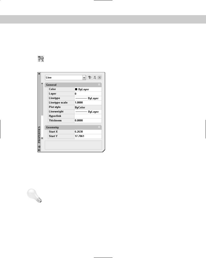
Editing with the Properties Palette
The Properties palette displays the properties of selected objects. You can also use the Properties palette to change the properties of objects.
To open the Properties palette, click Properties on the Standard toolbar. (You can also choose Tools Properties or press Ctrl+1.) The Properties palette, shown in Figure 10-40,
opens on your screen.
|
Figure 10-40: Use the Properties palette to |
|
edit objects and their properties. |
|
Managing the Properties palette |
|
The new auto-hide feature of the Properties palette makes it easy to work with the palette |
|
open all the time. Whenever the cursor is off the palette, it collapses to just the title bar. To |
|
auto-hide the palette, right-click the title bar and choose Auto-hide. |
Tip |
The Properties palette has its own undo function. Right-click the item that you changed in the |
|
Properties palette and choose Undo. Multiple levels of undo are available. For more informa- |
|
tion about palettes, see Chapter 26. |
|
You can dock the Properties palette. Drag the window to the left or right of your screen. To |
|
resize the window, point to its edge until you see the double-headed arrow cursor, and then |
|
click and drag. You can also resize the two columns by pointing to the column dividing line |
|
until you see the double-headed arrow and then clicking and dragging. If the Properties |
|
palette has too many rows for its size, use the scroll bar to see the undisplayed rows. |
Chapter 10 Editing Your Drawing: Advanced Tools |
223 |
Using the Properties palette
The Properties palette can be used to directly edit objects and to edit other object properties as well:
You can change the layer, color, linetype, linetype scale, and lineweight of objects. (See Chapter 11.)
You can edit text and text properties. (See Chapter 13.)
You can edit plot styles. (See Chapter 17.)
You can edit hyperlinks. (See Chapter 28.)
To change values in the Properties palette, do one of the following:
Click a value, select the text, type a new value, and press Enter.
Click a value, click the down arrow at its right, and choose from the drop-down list.
Click a value, click the Pick a Point button, and specify a new point by picking on the screen.
In Figure 10-40, you see the result of opening the Properties palette with one line selected. To change either endpoint of the selected line, type new coordinates in the Properties palette and press Enter. Of course, this method of editing a line is only useful when you know the absolute coordinates that you want. When you select a geometric property, such as Start X, the X coordinate of the line’s start point, you can also use the Pick a Point button that appears. You can click this button and then pick a new start point directly on your screen. The new point becomes the new start point of the line, changing both the X and Y coordinates of the start point if your pick point requires it.
The information you see in the Properties palette depends on the objects selected:
If no object is selected, you see only properties that apply to the entire drawing, such as UCS, current layer, and viewport data. You can select an object while the window is open to display data on that object.
If one object or one type of object (such as all lines) is selected, you see both general information and geometrical information on that object or object type.
If more than one type of object is selected, you see general information, such as layer, color, and linetype data, but no geometry data.
If more than one object is selected and you choose one type of object from the dropdown list at the top of the window, you see information applying only to that type of object. This drop-down list provides a quick way to filter the type of objects you can edit.
The Properties palette has three buttons at its upper-right corner.
Quick Select opens the Quick Select dialog box covered in the next section. The Quick Select dialog box lets you create a selection set according to specified criteria (for
example, all green lines). You can then change the properties of these green lines.
224 Part II Drawing in Two Dimensions
Select Objects enables you to select objects for editing in the Properties palette. After you select the objects you want, you can change their properties. If you’re going to pick
objects or use implied windowing, the Select Objects button is no advantage. You can just select the objects and apply changes in the Properties palette. However, if you want to use a fence or polygon method of selection, the Select Objects button is helpful. Follow these steps:
1.Click the Select Objects button.
2.On the command line, type the selection method that you want (such as f for fence) as you would if a command were active or you had started the SELECT command.
3.Select the objects that you want.
4.Press Enter to end object selection.
5.Use the Properties palette to make the desired changes. (You can also start an editing command to use with the selected objects.)
Toggle Value of PICKADD Sysvar turns PICKADD on and off. PICKADD changes how you select more than one object. When it’s on (set to 1), the default, you can continue to select objects and they’re added to the selection set. When it’s off (set to 0), you need to press Shift to add objects to the selection set; otherwise, selecting an object deselects previously selected objects.
Here’s how to change the PICKADD variable:
 When you see the 1, PICKADD is off. Click the button to turn PICKADD on.
 When you see the plus, PICKADD is on. Click the button to turn PICKADD off.
Click the Properties palette’s close box to close the window. I further cover the Properties palette in the next chapter and in later chapters as appropriate.
Selection Filters
Sometimes you need a more powerful way to select objects. For example, you may want to:
Select all the lines in your drawing to change their color
Check the arc radii of all your fillets
Find short line segments that should be erased
Before selection filters, you had to write an AutoLISP program to accomplish these functions. (Sometimes an AutoLISP program is still the easiest way to go. See Chapters 34 through 36.) Now you can create fairly complex filters that select only the objects you want.
Cross- |
Don’t confuse object selection filters with point filters. Chapter 4 covers point filters. |
Reference |
|

Chapter 10 Editing Your Drawing: Advanced Tools |
225 |
Using Quick Select to select objects
Quick Select, as its name suggests, is a quick, flexible, and simple way to create object selection filters. Use the FILTER command, covered in the following sections, to create more-complex filters and when you want to save filtering criteria for future use.
Start Quick Select in one of these ways:
Choose Tools Quick Select.
With no command active, right-click in the drawing area and choose Quick Select.
Click the Quick Select button in the Properties palette.
Type qselect on the command line.
The Quick Select dialog box opens, shown in Figure 10-41.
Figure 10-41: Use the Quick Select dialog box to quickly create a selection set of objects based on specified criteria.
To create a filter, start at the top of the dialog box and work your way down. Here’s how it works:
Apply to: By default the filter applies to the entire drawing, but you can use the Select Objects button to return to your drawing and select objects. The rest of the filter will then apply only to selected objects, called Current Selection in the drop-down list. If you use this feature at all, you would usually use a window to select an area of your drawing. (The Select Objects button is unavailable if Append to Current Selection Set is checked at the bottom of the dialog box.)
Object type: By default, the filter lists Multiple as the object type. Click the drop-down list to choose from the object types available in your drawing (or in your selection set if you created one), such as line, circle, ellipse, polyline, and so on. You can choose only one type of object. To create a filter that includes more than one type of object (but not all types), use the FILTER command, which I describe in the next section.
226 Part II Drawing in Two Dimensions
New
Feature
Properties: Here you choose the properties that you want to filter. (Most of these properties are covered in the next chapter.) The drop-down list includes all properties in the drawing’s database — these depend on the object type you chose. You can choose only one property. The values in the next two sections depend on your choice in the Properties section. If you want to create a filter that specifies criteria for more than one property, use the FILTER command.
Operator: After you’ve chosen a property, you can set it equal to or not equal to a certain value. You can set certain properties as greater than or less than a value. You can use wildcard matching characters (such as * and ?) for editable text. Choose the desired operator from the drop-down list.
Value: Here you finally choose the value for your property. For example, you can set the color equal (or not equal) to green or the linetype equal to DASHED. Choose the desired value from the drop-down list or enter a value in the text box.
You can now choose Block Reference as the object type, Name as the property, and the name of a block as the Value to select all instances of that block.
How to apply: As soon as you create a filter, you can use it to create a selection set. To do this, check Include In New Selection Set. You can also use Quick Select to select everything except objects that meet your selection criteria — to do so, choose Exclude From New Selection set.
Append to current selection set: Check this box to add to an existing selection set objects meeting your criteria.
Click OK to select the objects meeting your criteria and close the dialog box. You can start a command and use the selection set. If the command must be started before selecting objects, you can use the Previous option (type p ) at the Select objects: prompt to select the objects selected by using Quick Select.
The Express Tools include two commands to create filtered selection sets. FASTSELECT creates a selection set of objects that touch the object you pick. You can create chains of objects to include objects that touch other touching objects. Choose Express Selection Tools Fast Select. GETSEL creates a selection of objects of the layer and object type that you select. Choose Express Selection Tools Get Selection Set. For information on installing Express Tools, see Appendix A.
Using the FILTER command
The advantage of using the FILTER command over Quick Select is that you can create morecomplex filters and save them.
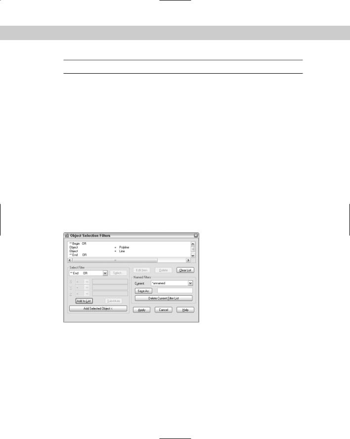
To create a filter, type filter on the command line to open the Object Selection Filters dialog box, as shown in Figure 10-42. If you’ve already chosen a command, type 'filter at the Select objects: prompt to create the selection filter transparently. The box at the top of the dialog box lists the filters you specified.
Note |
The selection filter only finds colors and linetypes of objects that have been specifically set as |
|
such, rather than as part of a layer definition. Chapter 11 covers layers, colors, and linetypes. |

Chapter 10 Editing Your Drawing: Advanced Tools |
227 |
Figure 10-42: The Object Selection Filters dialog box.
Creating a single filter
Use the Select Filter section of the dialog box to specify a filter. The drop-down box lists all the possible filters. Click the arrow to drop the list down. You can choose from several types of items:
Objects
Object properties such as color or layer
Object snaps such as arc center or circle radius
Logical operators such as AND, OR, and NOT (these logical operators combine filter specifications in various ways)
The first step is to choose a filter. In Figure 10-43, Line was chosen from the drop-down list. If the item chosen does not need any further clarification, click Add to List. The filter appears in the box at the top of the dialog box. Notice that the filter appears as Object = Line.
Figure 10-43: A filter that chooses all lines.

228 Part II Drawing in Two Dimensions
Many filters require a value. You have two ways to enter a value:
If you choose an object that can be listed, the Select button becomes active. Click it and choose the value you want. For example, if you choose Color or Layer, you choose from a list of colors or layers.
If you choose an object that can have any value, the boxes below the drop-down list box become active. They are labeled X, Y, and Z, but this is misleading. These boxes are used for X, Y, and Z coordinates only when you choose a filter requiring coordinates, such as Viewport Center. In most cases, you use the X box to give the filter a value. In this situation, the Y and Z boxes are not used. For example, if you choose Text Height, you type the height in the X box.
However, you don’t always want to specify that a filter equals a value. Let’s say you want to create a filter that selects all circles with a radius less than 0.75. When you choose Circle Radius, the X box becomes active. Click the arrow to drop down the list of relational operators and choose one. Table 10-2 lists the relational operators.
Table 10-2: Relational Operators in the Object Selection Filters Dialog Box
Operator |
Definition |
|
|
= |
Equal to |
!= |
Not equal to |
< |
Less than |
<= |
Less than or equal to |
> |
Greater than |
>= |
Greater than or equal to |
* |
Equal to any value |
|
|
Adding a second filter
To add a second filter, you first decide on the relationship between the first and the second filter and then assign a logical operator. Logical operators always come in pairs — when you begin one, you must also end it. The logical operators are at the end of the drop-down list of filter objects.
Note When two or more filters are listed without logical operators, the filter calculates them as if they were grouped with the AND operator. This means that the filter only selects objects that meet all the criteria specified.
Table 10-3 explains the four logical operators (called grouping operators because they group filter specifications together). The Example column explains the results of two filter specifications: Color = 1-Red and Object = Circle.
Chapter 10 Editing Your Drawing: Advanced Tools |
229 |
Table 10-3: Logical (or Grouping) Operators Used for Selection Filters
Operator |
Explanation |
Example |
|
|
|
AND |
Finds all objects that meet all criteria |
Finds red circles |
OR |
Finds objects that meet any of the criteria |
Finds all red objects and all circles |
XOR |
Finds objects that meet one criterion or the |
Finds red objects that are not circles and |
|
other but not both. Requires two criteria |
circles that are not red |
|
between Begin XOR and End XOR |
|
NOT |
Excludes objects that meet the criteria. |
If the NOT operator groups the Object = Circle |
|
May only have one criterion between |
filter, finds all red objects that are not circles |
|
Begin NOT and End NOT |
|
|
|
|
Click Substitute and choose a saved filter to insert a saved filter into the filter you’re currently defining. To add filters based on existing objects, choose Add Selected Object. This action adds all the properties of the object to the filter definition — which is often more than you want.
Figure 10-44 shows a filter that selects all lines and all polylines. The XOR operator was used because it finds objects that meet one criterion or the other but not both. Obviously, no object can be both a line and a polyline. This is a good example of a filter that you cannot create using Quick Select.
Figure 10-44: A filter that selects all lines and all polylines.
Naming and editing filters
After you’ve completed the filter, you should save it. Even if you don’t think you’ll use it again, you may make an editing error in the drawing while using it and have to go back to it. To save a filter, type a name in the Save As text box and click Save As.
230 Part II Drawing in Two Dimensions
You edit a listed filter by using three buttons:
Edit Item: Choose the line containing the item and click this button to edit the item. The object name is now in the drop-down box and you can specify new values for it.
Delete: Choose Delete to delete a chosen item in a filter.
Clear List: Choose Clear List to clear all the items in a filter and start over.
To choose a named filter to edit, choose it from the Current drop-down list.
Using filters
You can use filters in two ways. Most often, you choose a command first and then realize that you need a filter to select the objects. Follow these prompts:
Select objects: 'filter
Define the filter in the Object Selection Filters dialog box. Click Apply.
Applying filter to selection.
Select objects: Type all or use a large selection window to select all the objects you want to consider in the filter.
x found
y were filtered out Select objects:
Exiting filtered selection. x found Select objects:
The command’s usual prompts then continue.
Alternatively, you can start the FILTER command and define the filter. Click Apply. At the Select objects: prompt, type all or use a selection window. Press Enter to end object selection. Then start the editing command and use the Previous selection option to select the filtered objects.
On the |
The drawing used in the following Step-by-Step exercise on using selection filters, ab10-k. |
CD-ROM |
dwg, is in the Drawings folder on the CD-ROM. |
STEP-BY-STEP: Using Selection Filters
1.Open ab10-k.dwg from the CD-ROM.
2.Save the file as ab10-13.dwg in your AutoCAD Bible folder. Notice that two lines of text appearing in the middle of the drawing plus the text at the bottom of the drawing are black/white rather than blue like all the other text. You want to check the color of all the text and correct it if necessary.
3.Right-click the drawing area and choose Quick Select. In the Quick Select dialog box, click the Object Type drop-down list and scroll down until you see Text. Choose it.
4.In the Properties section, Color should be selected. If not, select it. In the Operator section, choose Not Equal. In the Value section, choose ByLayer. Include In New Selection Set should be chosen. Append to Current Selection Set should not be checked. Click OK to select three items of black/white text.