

- •Foreword
- •Preface
- •Is This Book for You?
- •How This Book Is Organized
- •How to Use This Book
- •Doing the Exercises
- •Conventions Used in This Book
- •What the Icons Mean
- •About the CD-ROM
- •Other Information
- •Contacting the Author
- •Acknowledgments
- •Contents at a Glance
- •Contents
- •Getting Acquainted with AutoCAD and AutoCAD LT
- •Starting AutoCAD and AutoCAD LT
- •Creating a New Drawing
- •Using the AutoCAD and AutoCAD LT Interface
- •Creating Your First Drawing
- •Saving a Drawing
- •Summary
- •Creating a New Drawing from a Template
- •Working with Templates
- •Opening a Drawing with Default Settings
- •Opening an Existing Drawing
- •Using an Existing Drawing as a Prototype
- •Saving a Drawing Under a New Name
- •Summary
- •The Command Line
- •Command Techniques
- •Of Mice and Pucks
- •Getting Help
- •Summary
- •Typing Coordinates
- •Displaying Coordinates
- •Picking Coordinates on the Screen
- •Locating Points
- •Summary
- •Unit Types
- •Drawing Limits
- •Understanding Scales
- •Inserting a Title Block
- •Common Setup Options
- •The MVSETUP Command
- •Summary
- •Using the LINE Command
- •Drawing Rectangles
- •Drawing Polygons
- •Creating Construction Lines
- •Creating Rays
- •Summary
- •Drawing Circles
- •Drawing Arcs
- •Creating Ellipses and Elliptical Arcs
- •Making Donuts
- •Placing Points
- •Summary
- •Panning
- •The ZOOM Command
- •Aerial View
- •Named Views
- •Tiled Viewports
- •Snap Rotation
- •User Coordinate Systems
- •Isometric Drawing
- •Summary
- •Editing a Drawing
- •Selecting Objects
- •Summary
- •Copying and Moving Objects
- •Using Construction Commands
- •Creating a Revision Cloud
- •Hiding Objects with a Wipeout
- •Double-Clicking to Edit Objects
- •Grips
- •Editing with the Properties Palette
- •Selection Filters
- •Groups
- •Summary
- •Working with Layers
- •Changing Object Color, Linetype, and Lineweight
- •Working with Linetype Scales
- •Importing Layers and Linetypes from Other Drawings
- •Matching Properties
- •Summary
- •Drawing-Level Information
- •Object-Level Information
- •Measurement Commands
- •AutoCAD’s Calculator
- •Summary
- •Creating Single-Line Text
- •Understanding Text Styles
- •Creating Multiline Text
- •Creating Tables
- •Inserting Fields
- •Managing Text
- •Finding Text in Your Drawing
- •Checking Your Spelling
- •Summary
- •Working with Dimensions
- •Drawing Linear Dimensions
- •Drawing Aligned Dimensions
- •Creating Baseline and Continued Dimensions
- •Dimensioning Arcs and Circles
- •Dimensioning Angles
- •Creating Ordinate Dimensions
- •Drawing Leaders
- •Using Quick Dimension
- •Editing Dimensions
- •Summary
- •Understanding Dimension Styles
- •Defining a New Dimension Style
- •Changing Dimension Styles
- •Creating Geometric Tolerances
- •Summary
- •Creating and Editing Polylines
- •Drawing and Editing Splines
- •Creating Regions
- •Creating Boundaries
- •Creating Hatches
- •Creating and Editing Multilines
- •Creating Dlines
- •Using the SKETCH Command
- •Digitizing Drawings with the TABLET Command
- •Summary
- •Preparing a Drawing for Plotting or Printing
- •Creating a Layout in Paper Space
- •Working with Plot Styles
- •Plotting a Drawing
- •Summary
- •Combining Objects into Blocks
- •Inserting Blocks and Files into Drawings
- •Managing Blocks
- •Using Windows Features
- •Working with Attributes
- •Summary
- •Understanding External References
- •Editing an Xref within Your Drawing
- •Controlling Xref Display
- •Managing Xrefs
- •Summary
- •Preparing for Database Connectivity
- •Connecting to Your Database
- •Linking Data to Drawing Objects
- •Creating Labels
- •Querying with the Query Editor
- •Working with Query Files
- •Summary
- •Working with 3D Coordinates
- •Using Elevation and Thickness
- •Working with the User Coordinate System
- •Summary
- •Working with the Standard Viewpoints
- •Using DDVPOINT
- •Working with the Tripod and Compass
- •Getting a Quick Plan View
- •Shading Your Drawing
- •Using 3D Orbit
- •Using Tiled Viewports
- •Defining a Perspective View
- •Laying Out 3D Drawings
- •Summary
- •Drawing Surfaces with 3DFACE
- •Drawing Surfaces with PFACE
- •Creating Polygon Meshes with 3DMESH
- •Drawing Standard 3D Shapes
- •Drawing a Revolved Surface
- •Drawing an Extruded Surface
- •Drawing Ruled Surfaces
- •Drawing Edge Surfaces
- •Summary
- •Drawing Standard Shapes
- •Creating Extruded Solids
- •Drawing Revolved Solids
- •Creating Complex Solids
- •Sectioning and Slicing Solids
- •Using Editing Commands in 3D
- •Editing Solids
- •Listing Solid Properties
- •Summary
- •Understanding Rendering
- •Creating Lights
- •Creating Scenes
- •Working with Materials
- •Using Backgrounds
- •Doing the Final Render
- •Summary
- •Accessing Drawing Components with the DesignCenter
- •Accessing Drawing Content with Tool Palettes
- •Setting Standards for Drawings
- •Organizing Your Drawings
- •Working with Sheet Sets
- •Maintaining Security
- •Keeping Track of Referenced Files
- •Handling Errors and Crashes
- •Managing Drawings from Prior Releases
- •Summary
- •Importing and Exporting Other File Formats
- •Working with Raster Images
- •Pasting, Linking, and Embedding Objects
- •Summary
- •Sending Drawings
- •Opening Drawings from the Web
- •Creating Object Hyperlinks
- •Publishing Drawings
- •Summary
- •Working with Customizable Files
- •Creating Keyboard Shortcuts for Commands
- •Customizing Toolbars
- •Customizing Tool Palettes
- •Summary
- •Creating Macros with Script Files
- •Creating Slide Shows
- •Creating Slide Libraries
- •Summary
- •Creating Linetypes
- •Creating Hatch Patterns
- •Summary
- •Creating Shapes
- •Creating Fonts
- •Summary
- •Working with Menu Files
- •Customizing a Menu
- •Summary
- •Introducing Visual LISP
- •Getting Help in Visual LISP
- •Working with AutoLISP Expressions
- •Using AutoLISP on the Command Line
- •Creating AutoLISP Files
- •Summary
- •Creating Variables
- •Working with AutoCAD Commands
- •Working with Lists
- •Setting Conditions
- •Managing Drawing Objects
- •Getting Input from the User
- •Putting on the Finishing Touches
- •Summary
- •Understanding Local and Global Variables
- •Working with Visual LISP ActiveX Functions
- •Debugging Code
- •Summary
- •Starting to Work with VBA
- •Writing VBA Code
- •Getting User Input
- •Creating Dialog Boxes
- •Modifying Objects
- •Debugging and Trapping Errors
- •Moving to Advanced Programming
- •A Final Word
- •Installing AutoCAD and AutoCAD LT
- •Configuring AutoCAD
- •Starting AutoCAD Your Way
- •Configuring a Plotter
- •System Requirements
- •Using the CD with Microsoft Windows
- •What’s on the CD
- •Troubleshooting
- •Index

452 Part II Drawing in Two Dimensions
Summary
Several types of complex objects add greatly to the capabilities of AutoCAD and AutoCAD LT. In this chapter, you read about:
Using polylines to combine lines, segments, and arcs of any width into one object
Utilizing splines to mathematically calculate curves fit to points that you specify
Using regions, which are two-dimensional surfaces
Creating regions or polylines from complex areas by using the BOUNDARY command
Filling in an area with lines, a solid fill, or a gradient with hatches
Drawing complex parallel lines at one time with multilines (AutoCAD only) and drawing double lines with AutoCAD LT
Drawing freehand by using the SKETCH command, creating either lines or polylines (AutoCAD only)
Using a digitizer in Tablet mode, when you need to copy a paper drawing into AutoCAD In the next chapter, I explain how to lay out and plot a drawing.

Plotting and
Printing Your
Drawing
Most drawing jobs are not complete until you see the final result on paper. Traditionally, drawings are plotted on a plotter.
However, you can also print a drawing on regular computer printer. Many printers and plotters can handle a wide range of drawing sizes and paper types. In this chapter, I explain the process of preparing a drawing for plotting, including laying it out in paper space, more properly known as a layout. Finally, I cover the actual process of creating a plot.
You can have more than one layout for a drawing. You access a layout by clicking one of the layout tabs at the bottom of the drawing area.
Preparing a Drawing for
Plotting or Printing
When you complete your drawing, you often have some details to finish. If you didn’t start with a title block, you may need to insert one. Even if you have a title block, you may need to complete some of its annotation — such as the date you completed the drawing. If the drawing has layers that you don’t want to appear on paper, you should set their layer state to Frozen, Off, or Not Plottable.
Many architectural and mechanical drawings show several views of the model. Now is the time to check that the views are pleasingly laid out with enough space between them for dimensions and annotation.
Doing a draft plot
17C H A P T E R
In This Chapter
Preparing a drawing for plotting or printing
Creating a layout in paper space
Working with plot styles
Plotting a drawing
You may want to do a draft plot, either to check the drawing itself or to be sure it will print out properly. Although you can preview the plot, sometimes the results are not what you want, and it pays to test the
454 Part II Drawing in Two Dimensions
plot on inexpensive paper before plotting on expensive vellum. Draft plots for checking purposes can often be done on a printer. Some companies have inkjet printers or plotters that accept 17-x-22-inch paper and are used exclusively for check plots. Even if the final plot will be all in black, color printers are a good choice for draft plots because you can easily check the layer scheme.
Plotting a drawing from model space
Model space refers to the mode you work in when you draw and edit your model. Throughout this book, you’ve been working in model space. The Model tab at the bottom of the drawing area visually confirms that you’re in model space. After you’ve prepared your drawing for plotting, as just discussed, you can plot your drawing. See the discussion later in this chapter on plotting.
Creating a Layout in Paper Space
If you’re using several views of your model, you should consider creating a paper space layout. Although paper space was designed for the needs of 3D drawings, it’s often used for 2D layout as well. For example, if you want to show views of your model at different scales, paper space is indispensable. Paper space is a tool specifically for laying out several views of a drawing. It’s analogous to creating a sheet of paper at the size you’ll plot on and placing views on the paper. You place the views by means of floating viewports.
Cross- |
You can also plot entire drawing sets. For more information, see Chapter 26. |
Reference |
|
A layout provides a visual environment that lets you know what your plot will look like. By creating more than one layout for a drawing, you can create more than one plot for a single drawing. For example, you can create layouts at different scales for different sheet sizes.
Entering paper space
You draw in model space, which you access from the Model tab at the bottom of the screen. You use a paper space layout to lay out a drawing. When you’re in paper space, you can only view your drawing through floating viewports.
To enter a paper space layout, simply click a layout tab. By default, you see one floating viewport through which you can view your model. An example is shown in Figure 17-1. The paper space icon confirms that you’re looking at a paper space layout.
To switch back to model space, click the Model tab.
Using the Layout Wizard
The Layout Wizard automates the process of laying out a drawing in paper space. Although you may eventually want to lay out your drawings on your own, the Layout Wizard is a great way to get started using a paper space layout.

Chapter 17 Plotting and Printing Your Drawing |
455 |
Printable area of paper |
Floating viewpoint |
Paper space icon |
Paper size of currently configured plotter or printer |
Figure 17-1: When you click a layout tab, a layout is automatically created, with one floating viewport through which you can see your entire drawing.
To use the Layout Wizard, follow these steps:
1.Choose Tools Wizards Create Layout. You see the wizard screen shown in Figure 17-2, where you name the layout. This name will appear on the layout tab at the bottom of the drawing area.
2.Type a name for the layout and click Next.
Figure 17-2: The first screen of the Layout Wizard.
456 Part II Drawing in Two Dimensions
3.The second screen asks you to choose a configured plotter. This list also includes printers. For more information on configuring a plotter or printer, see Appendix A. Click Next after you’re done.
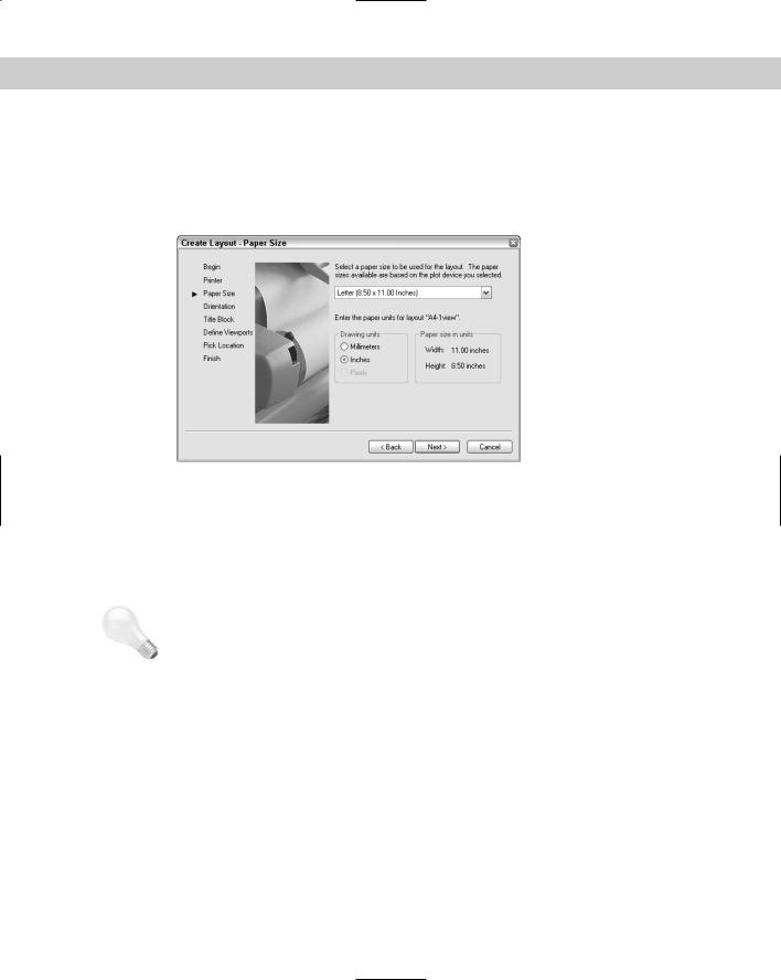
4.On the third screen, shown in Figure 17-3, specify a paper size and drawing units and then click Next.
Figure 17-3: The Paper Size screen of the Layout Wizard.
5.On the next screen, specify if you want the drawing to plot in portrait or landscape orientation. The wizard rotates a letter A on a sheet of paper so that you can see which way your drawing will plot. Then click Next.
6.On the Title Block screen, shown in Figure 17-4, choose a title block if you want to add one. You can add it as a block (see Chapter 18) or as an external reference (or xref — see Chapter 19).
Tip |
To add your own title block, create it as a drawing and save it in the \Templates folder or |
|
create your own folder for your templates. (To find the location of the \Templates folder, |
|
choose Tools Options and click the Files tab. Double-click Drawing Template Settings and |
|
then Drawing Template File Location. To use your own folder, change this location. Using |
|
your own folder reduces the chance that you’ll lose your templates when you reinstall or |
|
upgrade.) Notice that most of the templates in that folder have corresponding drawings that |
|
are used in the Layout Wizard. If you have a template that you use for a title block, open a |
|
new drawing using that template and save it as a drawing in the \Templates folder, using |
|
the same name as the template. (It has a DWG filename extension, however.) |
7.On the Define Viewports screen, shown in Figure 17-5, you choose from four viewport configuration options:
•Choose None if you want to create your own floating viewports.
•Choose Single to create one viewport.
•Choose Std. 3D Engineering Views to create a 2×2 array of top, front, side, and isometric views.
•Choose Array to specify how many views you want, in rows and columns.
You also set the viewport scale. Then click Next.

Chapter 17 Plotting and Printing Your Drawing |
457 |
Figure 17-4: The Title Block screen of the Layout Wizard.
Cross-
Reference
For more information on scales, see Chapter 5. Also see the discussion of viewport scales later in this chapter.
Figure 17-5: The Define Viewports screen of the Layout
Wizard.
8.On the Pick Location screen, the wizard prompts you to pick two corners to define the size of the viewport configuration you chose. If you chose more than one viewport, these two corners define the extents of all the viewports combined, not the extents of the individual viewports.
9.Click Finish to close the wizard and return to your drawing.
Figure 17-6 shows the result of completing the wizard with a 2×2 array of viewports. You would still need to scale and pan the model to get the views you want in each viewport.
In the following exercise, you practice using the Layout Wizard to create a paper space layout.

458 Part II Drawing in Two Dimensions
Figure 17-6: After completing the Layout Wizard, you now see your model in the viewport(s) you created.
On the |
The drawing used in the following Step-by-Step exercise on creating a paper space layout |
CD-ROM |
with the Layout Wizard, ab17-a.dwg, is in the Drawings folder on the CD-ROM. |
STEP-BY-STEP: Creating a Paper Space
Layout with the Layout Wizard
1.Open ab17-a.dwg from your CD-ROM.
2.Save the file as ab17-01.dwg in your AutoCAD Bible folder.
3.Choose Tools Wizards Create Layout.
4.On the Begin screen, type Double as the name of the layout. Click Next.
5.On the Printer screen, choose the printer or plotter that you want to use. Click Next.
6.On the Paper Size screen, choose a paper size that you have available and that is suitable for the printer or plotter you chose on the previous screen. The drawing units should be inches (but you can use millimeters, if you want). Click Next.
7.On the Orientation screen, choose Landscape. (This is the default.) Click Next.
8.On the Title Block screen, choose ANSI A title block.dwg. The type should be set to Block. Click Next.
9.On the Define Viewports screen, choose Array. Set Rows to 1 and Columns to 2. Choose 1:4 from the Viewport Scale drop-down list. Click Next.
10.On the Pick Location screen, click Select Location. In the drawing, choose a point near the top of the border on the left and a second point at the bottom-right of the border, just above the title block. If necessary, turn off OSNAP.
11.Click Finish.
Chapter 17 Plotting and Printing Your Drawing |
459 |
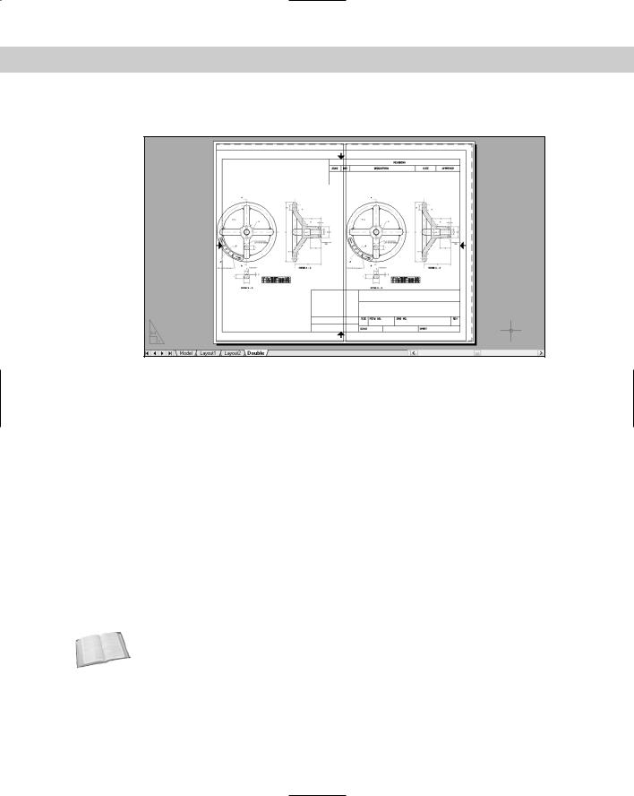
12. Save your drawing. It should look like Figure 17-7.
Figure 17-7: Using the Layout Wizard to create a paper space layout with floating viewports.
Laying out a drawing in paper space on your own
Now that you’ve used the Layout Wizard once, you can try creating layouts on your own. The Layout Wizard only creates the floating viewports, leaving most of the scaling, the panning, and other tasks up to you.
Working with layout tabs
You can have up to 256 layouts, including the model tab. To create a new layout, right-click an existing layout tab to open the shortcut menu.
The following shortcut menu options help you manage layouts:
Cross-
Reference
New layout: Creates a new layout tab.
From template: Opens the Select File dialog box in which you can choose a .dwg, .dxf, or .dwt file. Click Open. You can then choose the layout or layouts you want from the Insert Layout(s) dialog box. When you import a template, you import everything that exists on the paper space layout, including viewports and any existing text, title block, and so on. (You can then get rid of anything you don’t want, if necessary.)
If you import a layout from a drawing, any layers, linetypes, and such also come along for the ride. Use the PURGE command to get rid of anything you don’t need. See Chapter 11 for information on purging. You can also import a layout using the DesignCenter. See Chapter 26 for details.
Delete: Deletes the selected layout. You get a warning dialog box. Click OK to delete the layout.
460 Part II Drawing in Two Dimensions
Rename: Opens the Rename Layout dialog box, where you can rename the layout. Click OK.
Move or Copy: Opens the Move or Copy dialog box. To move a layout tab, you choose the layout tab that you want the selected tab to be to the left of. You can also choose to move it to the end. Click Create a copy to copy the selected tab. (You can then rename it.) Click OK after you’re done.
Select All Layouts: Selects all layouts. You can then delete them.
Activate Previous Layout/Activate Model Tab: Moves you to the last layout tab you had displayed or to the Model tab.
Page Setup Manager: Opens the Page Setup Manager, discussed next.
Plot: Opens the Plot dialog box, discussed later in this chapter.
Tip |
To move through the tabs (Model and all the layout tabs) from left to right, press Ctrl+Page |
|
Down. To move from right to left, press Ctrl+Page Up. |
Using the Page Setup Manager and dialog box
When you click a new (unused) layout tab, by default you see one floating viewport. However, you can create and save page setups that store many of the settings explained previously in the discussion of the Layout Wizard. The value in saving page setups is that the settings are attached to the layout. If you have more than one layout, each with its own page setup, you can quickly switch the page settings as you move from layout to layout. Once you have page setups, you can manage them in the new Page Setup Manager, shown in Figure 17-8.
Figure 17-8: The Page Setup Manager helps you control your page setups.
Chapter 17 Plotting and Printing Your Drawing |
461 |
Note |
You can check the Display When Creating a New Layout check box and the Page Setup dialog |
|
box will automatically appear each time you display a layout tab for the first time. To display |
|
it if it does not appear, right-click the current paperspace layout tab and choose Page Setup; |
|
then check the check box. You can also specify if you want the Page Setup Manager to |
|
appear when you click a new layout tab by choosing Tools Options and clicking the Display |
|
tab. Check or uncheck the Show Page Setup Manager for New Layouts check box. |
The Page Setup Manager lists your layouts and page setups. You can create a new page setup, modify an existing setup, or set a page setup current for the active layout. Click the Import button to import a page setup from another drawing.
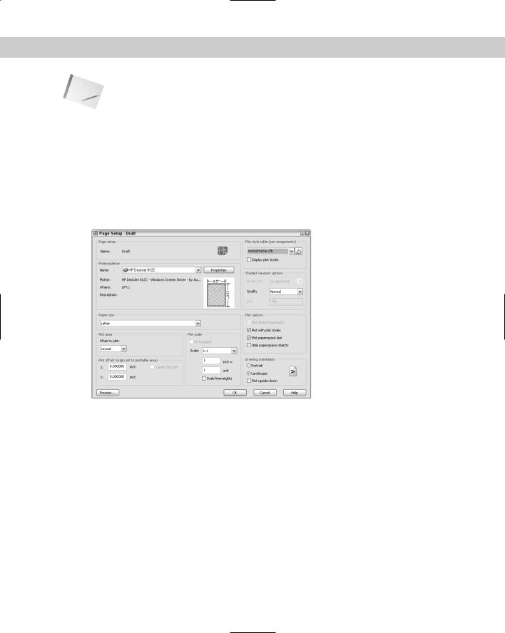
To create a new page setup, click New. In the New Page Setup dialog box, enter a name for the page setup. Choose an existing page setup to start from so that you don’t have to change all the settings, and click OK. The Page Setup dialog box appears, as shown in Figure 17-9.
Figure 17-9: The Page Setup dialog box.
Here’s how to use the Page Setup dialog box:
Printer/Plotter: Choose a printer or plotter from the drop-down list. For more information see “Choosing a plotter/printer” later in this chapter.
Paper size: Choose a paper size from the drop-down list.
Plot area: By default the plot is set to the layout. However, you can choose to plot the current display, the drawing extents, a named view, or a window that you specify.
Plot offset: You can move the plot from the lower-left corner. Specify the X and Y inches. If you aren’t plotting the layout, but rather some smaller area, check the Center the Plot check box to center the plot on the paper.
Plot scale: Set the scale from the drop-down list. You can also type a scale in the text boxes. Because you scale your model in your floating viewports, you usually don’t have to scale the layout as well. Therefore, you typically plot a layout in paper space at 1:1. If you’re using lineweights and want to scale them, check the Scale Lineweights check box.

462 Part II Drawing in Two Dimensions
Plot style table: Choose a plot style table if you want to use one. For more information, see the section “Working with Plot Styles” later in this chapter.
Shaded viewport options: Use this feature to determine the display of the Model tab. (To set the display of a viewport on a layout tab, select the viewport and make the changes in the Properties palette.) With the Model tab displayed, choose one of the four display options — As Displayed, Wireframe, Hidden, or Rendered. You can also choose a quality (resolution). If you choose the Custom quality, you can specify the dots per inch (dpi). (AutoCAD only.)
Plot options: Clear the Plot with Lineweights option if you used lineweights but don’t want the lineweights to be plotted. Clear Plot with Plot Styles if you assigned plot styles to layers or objects but don’t want to plot them. (Plot styles are discussed later in this chapter.) Clear the Plot Paperspace Last option in order to plot objects drawn on the paper space layout first. Check Hide paper space objects to hide lines of 3D objects that you created in paper space. (Later in this chapter, I explain how to hide lines of 3D objects created in model space, a more common situation.)
Drawing orientation: Choose portrait or landscape. You can also choose to plot upside-down. Use these settings to rotate a drawing when you plot it.
When you’ve completed your settings in the dialog box, click OK You return to the Page Setup Manager and can see the new page setup in the list. To make the page setup active, click Set Current. Then click Close to return to your drawing.
Note |
You can import settings saved in PCP or PC2 files from earlier releases of AutoCAD or AutoCAD |
|
LT. PCP and PC2 files contain plot settings similar to those you set in the Page Setup dialog |
|
box. Click the layout you want to use and choose Tools Wizards Import Plot Settings. In |
|
the Import PCP or PC2 Settings Wizard, follow the instructions to import the PCP or PC2 file. |
Preparing layers
If necessary, create the layers you need. If you want to insert a title block, create a separate layer for it. The actual viewports should also be on their own layer because it’s common to freeze that layer or set it to non-plottable, so that the borders don’t show. Even if you want to plot the viewports, making them a different color from your model helps you to easily distinguish them.
Inserting a title block
Insert the title block. You can have a file that contains just the title block. You can use a block or external reference. Putting the title block on your layout is common because it defines the edges of your paper and is not a real-life object. These qualities make it appropriate for paper space, which also relates to your paper, rather than the real-life model you’ve drawn.
Creating floating viewports
Remember that you need a floating viewport to see your model on a paper space layout. The default is one floating viewport. Floating viewports have the following properties that are important to understand when you’re creating layouts in paper space:
Unlike tiled viewports (see Chapter 8), floating viewports are actual objects that you can erase, move, and stretch. They can — and should — be on separate layers, so that you can control the visibility of the viewport borders when desired. They don’t need to take up the entire screen. You can define their size and location freely.
Chapter 17 Plotting and Printing Your Drawing |
463 |
In paper space, the crosshairs are not limited to one floating viewport.
You can separately set the visibility of the UCS icon in each floating viewport.
You can create as many viewports as you want, but it’s best to keep the drawing uncluttered.
Whatever you draw in paper space does not affect your models — it exists only in paper space and disappears when you return to the model space tab.
After you create floating viewports, you can switch to model space and work on your models while still on the layout tab — to do so, double-click inside a viewport. You do this mostly to adjust the view of the model in the viewport. In model space, floating viewports are similar to tiled viewports — only one can be active at a time.
Viewports are created on the current layer, so make the desired layer current. Then, to create floating viewports, choose View Viewports while on a layout tab. Choose from the following submenu items:
Named Viewports: If you’ve saved a tiled viewport configuration, choose this option to open the Viewports dialog box. On the Named Viewports tab, choose the configuration from the list and click OK. In other words, you can use a tiled viewport configuration for floating viewports.
Cross- |
See Chapter 8 for a full discussion of saving viewport configurations. |
Reference |
|
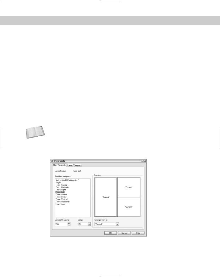
New Viewports: Choose this item to open the Viewports dialog box, shown in Figure 17-10. Choose one of the standard configurations, which you can see in the Preview box. Click OK to create the viewports.
Figure 17-10: Use the Viewports dialog box to choose one of the standard configurations of floating viewports.

464 Part II Drawing in Two Dimensions
1 Viewport: You get the Specify corner of viewport or [ON/OFF/Fit/Shadeplot/ Lock/Object/Polygonal/Restore/2/3/4] <Fit>: prompt on the command line. You can pick two diagonally opposite points or use the Fit option to create one viewport that fits the entire screen. Note that AutoCAD LT does not include the Object or Polygonal options. You cannot create non-rectangular viewports in AutoCAD LT.
2 Viewports: Creates two floating viewports. You can choose a horizontal or vertical configuration. You can choose Fit to fit them to the entire screen or pick diagonal points. The diagonal points define the combined two viewports, not each viewport.
3 Viewports: Creates three floating viewports. You can choose from several configurations. You can choose Fit to fit them to the entire screen or pick diagonal points. The diagonal points define the combined three viewports, not each viewport.
4 Viewports: Creates four floating viewports. You can choose Fit to fit them to the entire screen or pick diagonal points. The diagonal points define the combined four viewports, not each viewport.
Polygonal Viewport: (AutoCAD only) Lets you create a viewport using a combination of line segments and arcs, with prompts similar to those you see when creating a polyline (see Chapter 16 for information on creating polylines). Follow these steps to create a polygonal viewport:
1.At the Specify start point: prompt, pick a point.
2.At the Specify next point or Arc/ Length/Undo]: prompt, continue to specify points or right-click to choose one of the options. If you choose the Arc option, you see suboptions that are just like those you see when drawing an arc in a polyline.
3.Press Enter to use the Close option (which appears after you’ve specified two or more points) to complete the viewport.
Object: (AutoCAD only) Select an existing object, such as an ellipse, and the object turns into a viewport.
You now see your drawing in the new viewport(s).
New
Feature
Returning to model space while on a layout
The next step is to set the view in each viewport. To do this, you need to return to model space while still on the layout tab and make a viewport active. You can do this in two ways:
Click PAPER on the status bar. (The button then says MODEL.) Then click the viewport you want to become active.
Double-click inside the viewport you want to become active.
To help you work more easily in a viewport, you can now maximize the viewport temporarily without leaving the layout.
To maximize a viewport, pick the viewport border to select the viewport. Right-click and choose Maximize Viewport. (You can also double-click the viewport’s border.) The viewport takes up the entire screen and you see a red border around the edge. You can draw, edit, zoom, or pan in the view like you normally would in Model Space, but zooming and panning

Chapter 17 Plotting and Printing Your Drawing |
465 |
have no affect on the viewport’s view or scale. When you’ve finished making the desired changes, right-click and choose Minimize Viewport. The new commands that maximize and minimize a viewport are VPMAX and VPMIN. While you’re in a layout, you can use the following buttons on the status bar:
 Maximize Viewport: Maximizes the viewport to take up the entire screen
 Minimize Viewport: Returns the viewport to its original size
 Maximize Next Viewport: Switches to the next viewport, still maximized
 Maximize Previous Viewport: Switches to the previous viewport, still maximized
You can now access your models. Working with floating viewports in model space is quite similar to working with tiled viewports. The active viewport shows a dark border.
Tip |
To cycle from viewport to viewport while in model space, press Ctrl+R. |
Viewport scale
You’ll probably want to set the zoom for each viewport to exact scale. You can set the zoom in two ways:
From model space, choose Zoom Scale from the Zoom flyout of the Standard toolbar.
You need to use the inverse of the scale factor with the xp option of the ZOOM command. If you have an architectural drawing at a scale of 1:48, type 1/48xp . (The abbreviation xp stands for “times paper space.”) Each viewport can have its own scale.
If you’re still in paper space, select the viewport on its border. Choose Properties from the Standard toolbar to open the Properties palette. Choose Standard scale and choose one of the standard scales from the drop-down list that appears.
If you remain in model space with a viewport active, and then zoom in or out, you change the displayed scale of the model. After you set the scale, you can lock it to avoid this problem. To lock a viewport, select the viewport’s border (while in paper space, not model space) and choose Properties from the Standard toolbar to open the Properties palette. Choose Display locked and then choose Yes from the drop-down list. (Or select the viewport, right-click, and choose Viewport Locked Yes.) Now, when you zoom in and out, only paper space objects will be affected.
After you scale each viewport, you need to go back and pan until you see what you want in the viewport. If you can’t get it perfectly, don’t worry — you can also change the size of the viewport itself.
Setting viewport size, placement, and display
To adjust the viewports themselves, return to paper space by clicking MODEL on the status bar or by double-clicking anywhere outside a viewport (but in the drawing area). You cannot access your models anymore but now you can move and resize the viewports if necessary.
You can use grips to stretch and move them or use the STRETCH and MOVE commands.

466 Part II Drawing in Two Dimensions
The VPCLIP command is not available in AutoCAD LT.
The VPCLIP command enables you to redefine the boundary of an existing viewport. You can delete the boundary of a clipped viewport and change it to a rectangular viewport or create a polygonal boundary just as you do when creating a polygonal viewport.
To redefine the boundary of a viewport, you must be in paper space. Type vpclip on the command line. Select a clipped viewport boundary from paper space. At the Select clipping object or [Polygonal/Delete] <Polygonal>: prompt, you can select an object to use for the new boundary or press Enter to get the same prompts you see when you create a polygonal viewport. Right-click and choose Delete to delete the boundary of a clipped viewport (one created by choosing an object or using the Polygonal option).
You can also turn viewports on and off. When a viewport is off, it doesn’t display your model. Do this when the regeneration process becomes slow as a result of a large number of viewports or a complex drawing. To turn off a viewport, select it (in paper space), right-click and choose Display Viewport Objects No.
Setting layer visibility within a viewport
If you want, you can individually set layer visibility in floating viewports. For example, you might have some text or dimensions that appear in more than one floating viewport, but you may not want to show them more than once. Or perhaps you don’t want a hatch to appear in one of the viewports. You must be in model space — double-click in any viewport. To freeze a layer in an active viewport, click the Layer Control drop-down list on the Layers toolbar. Find the layer you want to freeze in that viewport and click the icon in the Freeze or Thaw in Current Viewport column. That layer disappears in the active viewport.
You can also freeze/thaw layers in new viewports — meaning viewports that you haven’t yet created. Choose Layer Properties Manager from the Layers toolbar to open the Layer Properties Manager. Click the icon for the layer you want in the New VP Freeze column and choose OK to close the dialog box.
Cross- |
Don’t forget that layers have a plottable/not plottable state. You can, therefore, set certain lay- |
Reference |
ers to not plottable if you don’t want them to appear on the plot. For more information, see |
|
|
|
Chapter 11. |
Setting hidden and shaded views for viewports
If you have a 3D drawing, you may want to hide back lines for objects in a viewport when you plot (similar to using the HIDE command on the Model tab). This procedure lets you hide lines in one viewport but not in others. You don’t see the result until you plot or display a plot preview. You can also specify shading and rendered views for each viewport, from both model space and paper space layouts, as shown in Figure 17-11.
To choose the type of shaded view, select any viewport in paper space. Right-click, and choose Shade Plot. Then choose one of the following options:
As Displayed: Plots the objects as they’re current displayed
Wireframe: Plots the objects in wireframe display

Chapter 17 Plotting and Printing Your Drawing |
467 |
Hidden: Plots objects with hidden lines removed
Rendered: Plots objects using the default rendering settings (See Chapter 25 for coverage on rendering. This option is not available in AutoCAD LT.)
Express Tools include several commands for working with layouts:
The CHSPACE command (Choose Express Layout Tools Change Space) moves objects from model space to paper space.
The ALIGNSPACE command (Choose Express Layout Tools Align Space) aligns objects in different viewports.
The VPSYNC command (Choose Express Layout Tools Synchronize Viewports) changes the pan and zoom of a second viewport to match that of the first (“master”) viewport you select, so that the view of the objects is consistent (synchronized) from viewport to viewport.
The VPSCALE command (Choose Express Layout Tools List Viewport Scale) displays the scale from paper space to model space of the selected viewport.
The LAYOUTMERGE command (Choose Express Layout Tools Merge Layout) moves all objects on one or more layouts that you specify to a single layout.
Figure 17-11: In this drawing, one viewport displays a wireframe, one a hidden view, and one a rendered view.
Adding text on a paper space layout
In general, text that relates directly to the model is created in model space — dimensions, leaders, and so on. However, annotation that applies to the entire drawing, title block text, or whatever, can be, and often is, created on the paper space layout. Change to a text layer and use the DTEXT or MTEXT command as usual.

468 Part II Drawing in Two Dimensions
Dimensions
Dimensioning is usually done in model space, but you can dimension in paper space as well. The Trans-Spatial Dimensioning feature automatically adjusts dimensions for the scale of the viewport. These paper space dimensions are fully associative. Dimensioning in paper space has several advantages:
You don’t have to worry about the size of the dimensions. If you plot from paper space you plot at 1:1 scale.
You can place the dimensions outside the border of the floating viewport, which may make it easier to fit the dimensions.
You can easily dimension just one view of the model. If you dimension in model space, you see the dimensions in all the viewports unless you freeze that layer in some of the viewports.
Tip |
If you create dimensions in a viewport in paper space and then zoom or pan in that viewport, |
|
the objects and the dimension get out of sync. Use the DIMREGEN command on the com- |
|
mand line to reset the dimension to match its object. |
You still need to scale the size of the dimension itself to your viewport scale, including the text, arrows, and so on:
1.Open the Dimension Style Manager.
2.Choose the dimension style you want to use and click Modify.
3.On the Fit tab, choose Scale Dimensions to Layout (Paper Space).
4.Click OK and then click Close.
When you follow this procedure, all the dimensions using the dimension style you chose appear the same size on your final plot.
Note Drawings created in earlier releases (before AutoCAD 2002 and AutoCAD LT 2002) do not automatically have the new associative dimensions. If necessary, change the DIMASSOC system variable’s value to 2. Also, you usually need to use the DIMREASSOCIATE command to associate existing dimensions to their objects. See Chapter 14 for more information on associative dimensions.
Saving a layout template
After you do all the work to create a layout, you can save it as a template so that you can use it in other drawings. Here’s how:
1.Type layout on the command line.
2.At the prompt, right-click and choose Save As.
3.At the Enter layout to save to template <Layout2>: prompt, press Enter to save the current layout, the name of which appears in brackets, or type the name of another layout tab.
4.The Create Drawing File dialog list opens, with the Template folder active. The Files of Type drop-down list shows Drawing Template File (*.dwt). Type a name for the drawing template and click Save.

Chapter 17 Plotting and Printing Your Drawing |
469 |
To use the template, in any drawing right-click a layout tab and choose From Template, as explained earlier in this chapter.
In the following exercise, you practice laying out a drawing in paper space using the same drawing you used in the previous exercise.
On the |
The drawings used in the following Step-by-Step exercise on laying out a drawing in paper |
CD-ROM |
space, ab17-a.dwg and ab-17a-blk.dwg, are in the Drawings folder on the CD-ROM. |
STEP-BY-STEP: Laying Out a Drawing in Paper Space
1.Open ab17-a.dwg from your CD-ROM.
2.Save the file as ab17-02.dwg in your AutoCAD Bible folder.
3.Click the Layout1 tab. Right-click the tab and choose Page Setup Manager.
4.Click New. In the New Page Setup Name text box, type PrinterDraft. Click OK. The Page Setup dialog box opens.
5.In the Paper Size section, set the paper size to Letter (8.50 11 Inches). (This enables you to plot to a printer if you don’t have a plotter available.) In the Shaded Viewport Options section, choose Draft from the Quality drop-down list. Make sure that your printer is listed in the Name drop-down list of the Printer/Plotter section. Click OK to return to the Page Setup Manager.
6.The PrinterDraft page setup should be highlighted. Click Set Current. Click Close.
7.Right-click the Layout1 tab and choose Rename. Name the tab 3-view. Click OK.
8.You see one floating viewport with the drawing displayed inside. Click its border and press the Delete key because you want to make your own viewports.
9.Click the Layer drop-down list arrow. Choose the Titleblk layer to make it current.
10.Choose Insert Block to open the Insert dialog box. Click Browse. Choose ab-17a- blk.dwg from the CD-ROM and click Open. Uncheck any checked Specify On-Screen checkboxes. Click OK to insert the title block, as shown in Figure 17-12.
11.Choose the np layer from the Layer Control drop-down list to make it current.
12.Choose View Viewports 1 Viewport. (Turn OSNAP off if it’s on.) At the Specify corner of viewport or [ON/OFF/Fit/Shadeplot/Lock/Object/Polygonal/ Restore/2/3/4] <Fit>: prompt, choose 1 in Figure 17-12. (If you are using AutoCAD LT, your prompt will look slightly different.) At the Specify opposite corner: prompt, choose 2.
13.Click the right mouse button and then choose Repeat 1 Viewport. At the prompt, choose 3 in Figure 17-12. At the next prompt, choose 4 in Figure 17-12. Again repeat the command and choose 5 and 6 in Figure 17-12. You now see the drawing in the three viewports.
14.Click the border of the top-left viewport. Choose Properties from the Standard toolbar
to open the Properties palette. Choose Custom Scale from the Properties palette. Type
.4 . Press Esc to deselect the top-left viewport.
470 Part II Drawing in Two Dimensions
1 5
2 6
3
4
Figure 17-12: The title block inserted into paper space.
15.Select the top-right viewport and set its custom scale to .4. Deselect the top-right viewport.
16.Select the bottom viewport. Choose Standard Scale in the Properties palette. Choose 2:1. This is equivalent to using a ZOOM 2xp, which is a scale factor of 1/2. Deselect the viewport.
17.Double-click inside each viewport in turn to switch to model space and pan until you see the view shown in Figure 17-13. It doesn’t have to match exactly. If you want, you can resize the viewports to fit the models better.
18.Double-click inside the bottom viewport. From the Layer Control drop-down list on the Layers toolbar, click the icon in the third column (Freeze or Thaw in Current Viewport) next to the DIM and HATCH layers to freeze those layers in the viewport. Click the name of the DIM-PS layer to make it current. The current dimension style, Style1, is already set to be scaled to paper space.
19.Double-click outside a viewport, but in the drawing area, to enter paper space. Choose Dimension Linear. Use the Quadrant object snap to create a dimension from the left quadrant to the right quadrant of the ellipse. The ellipse is correctly dimensioned at 1 unit, although it is zoomed in to a 1/2 scale.
20.Click the Layer Control drop-down arrow and change the current layer to Text. Click the Layer Control drop-down arrow again. Click the icon in the second column (Freeze or Thaw in ALL Viewports) next to the np layer. Click the top of the drop-down list to close it.
21.Choose Draw Text Single Line Text. Complete the text in the title block at the default height, as shown in Figure 17-13.
22.Save your drawing.