

- •Foreword
- •Preface
- •Is This Book for You?
- •How This Book Is Organized
- •How to Use This Book
- •Doing the Exercises
- •Conventions Used in This Book
- •What the Icons Mean
- •About the CD-ROM
- •Other Information
- •Contacting the Author
- •Acknowledgments
- •Contents at a Glance
- •Contents
- •Getting Acquainted with AutoCAD and AutoCAD LT
- •Starting AutoCAD and AutoCAD LT
- •Creating a New Drawing
- •Using the AutoCAD and AutoCAD LT Interface
- •Creating Your First Drawing
- •Saving a Drawing
- •Summary
- •Creating a New Drawing from a Template
- •Working with Templates
- •Opening a Drawing with Default Settings
- •Opening an Existing Drawing
- •Using an Existing Drawing as a Prototype
- •Saving a Drawing Under a New Name
- •Summary
- •The Command Line
- •Command Techniques
- •Of Mice and Pucks
- •Getting Help
- •Summary
- •Typing Coordinates
- •Displaying Coordinates
- •Picking Coordinates on the Screen
- •Locating Points
- •Summary
- •Unit Types
- •Drawing Limits
- •Understanding Scales
- •Inserting a Title Block
- •Common Setup Options
- •The MVSETUP Command
- •Summary
- •Using the LINE Command
- •Drawing Rectangles
- •Drawing Polygons
- •Creating Construction Lines
- •Creating Rays
- •Summary
- •Drawing Circles
- •Drawing Arcs
- •Creating Ellipses and Elliptical Arcs
- •Making Donuts
- •Placing Points
- •Summary
- •Panning
- •The ZOOM Command
- •Aerial View
- •Named Views
- •Tiled Viewports
- •Snap Rotation
- •User Coordinate Systems
- •Isometric Drawing
- •Summary
- •Editing a Drawing
- •Selecting Objects
- •Summary
- •Copying and Moving Objects
- •Using Construction Commands
- •Creating a Revision Cloud
- •Hiding Objects with a Wipeout
- •Double-Clicking to Edit Objects
- •Grips
- •Editing with the Properties Palette
- •Selection Filters
- •Groups
- •Summary
- •Working with Layers
- •Changing Object Color, Linetype, and Lineweight
- •Working with Linetype Scales
- •Importing Layers and Linetypes from Other Drawings
- •Matching Properties
- •Summary
- •Drawing-Level Information
- •Object-Level Information
- •Measurement Commands
- •AutoCAD’s Calculator
- •Summary
- •Creating Single-Line Text
- •Understanding Text Styles
- •Creating Multiline Text
- •Creating Tables
- •Inserting Fields
- •Managing Text
- •Finding Text in Your Drawing
- •Checking Your Spelling
- •Summary
- •Working with Dimensions
- •Drawing Linear Dimensions
- •Drawing Aligned Dimensions
- •Creating Baseline and Continued Dimensions
- •Dimensioning Arcs and Circles
- •Dimensioning Angles
- •Creating Ordinate Dimensions
- •Drawing Leaders
- •Using Quick Dimension
- •Editing Dimensions
- •Summary
- •Understanding Dimension Styles
- •Defining a New Dimension Style
- •Changing Dimension Styles
- •Creating Geometric Tolerances
- •Summary
- •Creating and Editing Polylines
- •Drawing and Editing Splines
- •Creating Regions
- •Creating Boundaries
- •Creating Hatches
- •Creating and Editing Multilines
- •Creating Dlines
- •Using the SKETCH Command
- •Digitizing Drawings with the TABLET Command
- •Summary
- •Preparing a Drawing for Plotting or Printing
- •Creating a Layout in Paper Space
- •Working with Plot Styles
- •Plotting a Drawing
- •Summary
- •Combining Objects into Blocks
- •Inserting Blocks and Files into Drawings
- •Managing Blocks
- •Using Windows Features
- •Working with Attributes
- •Summary
- •Understanding External References
- •Editing an Xref within Your Drawing
- •Controlling Xref Display
- •Managing Xrefs
- •Summary
- •Preparing for Database Connectivity
- •Connecting to Your Database
- •Linking Data to Drawing Objects
- •Creating Labels
- •Querying with the Query Editor
- •Working with Query Files
- •Summary
- •Working with 3D Coordinates
- •Using Elevation and Thickness
- •Working with the User Coordinate System
- •Summary
- •Working with the Standard Viewpoints
- •Using DDVPOINT
- •Working with the Tripod and Compass
- •Getting a Quick Plan View
- •Shading Your Drawing
- •Using 3D Orbit
- •Using Tiled Viewports
- •Defining a Perspective View
- •Laying Out 3D Drawings
- •Summary
- •Drawing Surfaces with 3DFACE
- •Drawing Surfaces with PFACE
- •Creating Polygon Meshes with 3DMESH
- •Drawing Standard 3D Shapes
- •Drawing a Revolved Surface
- •Drawing an Extruded Surface
- •Drawing Ruled Surfaces
- •Drawing Edge Surfaces
- •Summary
- •Drawing Standard Shapes
- •Creating Extruded Solids
- •Drawing Revolved Solids
- •Creating Complex Solids
- •Sectioning and Slicing Solids
- •Using Editing Commands in 3D
- •Editing Solids
- •Listing Solid Properties
- •Summary
- •Understanding Rendering
- •Creating Lights
- •Creating Scenes
- •Working with Materials
- •Using Backgrounds
- •Doing the Final Render
- •Summary
- •Accessing Drawing Components with the DesignCenter
- •Accessing Drawing Content with Tool Palettes
- •Setting Standards for Drawings
- •Organizing Your Drawings
- •Working with Sheet Sets
- •Maintaining Security
- •Keeping Track of Referenced Files
- •Handling Errors and Crashes
- •Managing Drawings from Prior Releases
- •Summary
- •Importing and Exporting Other File Formats
- •Working with Raster Images
- •Pasting, Linking, and Embedding Objects
- •Summary
- •Sending Drawings
- •Opening Drawings from the Web
- •Creating Object Hyperlinks
- •Publishing Drawings
- •Summary
- •Working with Customizable Files
- •Creating Keyboard Shortcuts for Commands
- •Customizing Toolbars
- •Customizing Tool Palettes
- •Summary
- •Creating Macros with Script Files
- •Creating Slide Shows
- •Creating Slide Libraries
- •Summary
- •Creating Linetypes
- •Creating Hatch Patterns
- •Summary
- •Creating Shapes
- •Creating Fonts
- •Summary
- •Working with Menu Files
- •Customizing a Menu
- •Summary
- •Introducing Visual LISP
- •Getting Help in Visual LISP
- •Working with AutoLISP Expressions
- •Using AutoLISP on the Command Line
- •Creating AutoLISP Files
- •Summary
- •Creating Variables
- •Working with AutoCAD Commands
- •Working with Lists
- •Setting Conditions
- •Managing Drawing Objects
- •Getting Input from the User
- •Putting on the Finishing Touches
- •Summary
- •Understanding Local and Global Variables
- •Working with Visual LISP ActiveX Functions
- •Debugging Code
- •Summary
- •Starting to Work with VBA
- •Writing VBA Code
- •Getting User Input
- •Creating Dialog Boxes
- •Modifying Objects
- •Debugging and Trapping Errors
- •Moving to Advanced Programming
- •A Final Word
- •Installing AutoCAD and AutoCAD LT
- •Configuring AutoCAD
- •Starting AutoCAD Your Way
- •Configuring a Plotter
- •System Requirements
- •Using the CD with Microsoft Windows
- •What’s on the CD
- •Troubleshooting
- •Index
806 Part V Organizing and Managing Drawings
You can configure how the Communication Center works. Right-click the Communication Center icon or choose settings from the Communication Center window to open the Configuration Settings dialog box, with two tabs:
Settings: Use this tab to specify your country, how often you want to check for updates, and whether you want to see the bubble notification.
Channels: Choose the types of updates you want to see.
Renaming named objects
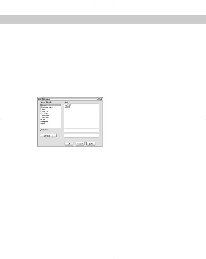
Drawings contain many named objects, such as layers, text styles, dimension styles, and so on. Sometimes you need to rename these objects in order to maintain CAD standards and consistency. To rename objects, type rename on the command line and press Enter, to open the Rename dialog box, shown in Figure 26-19.
Figure 26-19: The Rename dialog box.
To rename objects, follow these steps:
1.Choose the type of object you want to rename from the Named Objects list.
2.Choose the item you want to rename from the Items list. This item appears in the Old Name text box.
3.In the Rename To text box, type the new name for the item.
•If you want to change only one item, click OK to close the dialog box.
•If you want to change more than one item, click Rename To. The dialog box remains open so that you can make other changes. Click OK after you’re finished.
Organizing Your Drawings
Some offices keep track of thousands of drawings. You must not only track your drawings’ names and other properties but also make sure you don’t lose them! Archiving and finding drawings are important procedures in any CAD environment.

Chapter 26 Keeping Control of Your Drawings |
807 |
Archiving drawings
You should use the Autosave feature to save a backup of the drawing to the hard drive regularly. The default time has finally been changed to 10 minutes, but automatic backups can still be useful. Choose Tools Options, click the Open and Save tab, and change the Automatic Save setting. Click OK. Of course, you shouldn’t rely on Autosave; instead, save your drawing frequently by clicking the Save button.
Backing up to the hard drive doesn’t provide sufficient security. Hard drives can fail. Every time you exit AutoCAD or AutoCAD LT, you should back up every drawing you worked on to some type of external storage medium. Backing up drawings for storage is called archiving.
On the
CD-ROM
On the CD-ROM, I include an AutoLISP program, savea.lsp, that backs up to the a: drive without leaving your drawing. This enables you to back up while working on a drawing. See the Software\Chap01\Savea folder of the CD-ROM. This program works with AutoCAD only.
Some drawings are too large to fit on a floppy disk, and the number of disks you need to store all your drawings may make easy storage impossible. You’ll probably want to invest in one of the many types of removable backup systems. These come in four main types:
Tape drives (internal or external) are cheap and good for entire hard drive backups.
Disk cartridge drives offer the convenience of a floppy disk but with more capacity.
Read/write DVD-ROM or CD-ROM drives enable you to write to a DVD or CD-ROM.
Optical drives have the longest life (at least 30 years) and resist accidental erasure.
If your drawings are really important to you, back them up twice and store one backup set off-site. This way, if your office burns down, you haven’t lost everything. Remote backup services provide this type of archiving for you, and you can access your files via modem or the Internet.
The secret to backing up is to create a schedule and then stick to it. For example, you may do a complete hard-drive backup once a week, and do drawing backups at the end of each day. Each situation is different, but take the time to think about your needs, create a system, and let everybody know about it. Then do it.
|
Finding drawings |
|
Let’s say your client calls and says, “I want to see the apartment building on Fourth Street that |
|
you did three years ago.” How do you find the drawing? |
|
One low-tech way is to keep a book of 81⁄2×11 plots. Using the PUBLISH command (which I |
|
explain in Chapter 28), you can plot out a week’s drawings overnight and put them in a book. |
|
Amazingly, it doesn’t take that long to leaf through even a few hundred pages. (You usually |
|
have some idea of when you did the drawing.) |
Tip |
Place the drawing name and date written in large text on a separate layer in the drawing. Set |
|
the Plot property of the layer to Not Plottable while you work and for regular plotting. Set it |
|
to Plottable for your batch plots. Then, even reduced, you’ll know the drawing name when |
|
you look at the drawing in the book. |

808 Part V Organizing and Managing Drawings
A number of third-party drawing management programs are available. Some of these enable you to view and manage drawings created in other CAD programs as well. Some also manage workflow by letting you route drawings to team members.
Here’s a short selection of the many drawing management programs available:
AutoEDMS: www.acssoftware.com
Altris eB: www.altris.com
Cyco AutoManager Workflow EDM: www.cyco.com
Columbus: www.oasys-software.com/product/downloads
A fairly new option is to store and manage drawings online. Web-based services, such as Autodesk Buzzsaw (www.buzzsaw.com) let you store drawings online, view them, mark them up, organize and track them, and access them.
Before backing up drawings, purge any unused layers, blocks, text styles, and so on to reduce file size.
If you know a drawing is on the hard drive, you can use the Find function from within AutoCAD or AutoCAD LT. Click Open on the Standard toolbar. In the Select File dialog box, choose Tools Find to open the Find dialog box, shown in Figure 26-20. Use the Name & Location tab to set criteria according the filename, file type, and location. Use the Date Modified tab to set criteria by the date the file was saved.
Figure 26-20: You can use the Find dialog box to set criteria for finding drawings.
Specifying drawing properties
You can specify drawing properties, similar to those found in Microsoft Office. You can use these properties not only in the DesignCenter, but in Windows Explorer. These properties are therefore available to people who can access your drawings but who don’t have AutoCAD or AutoCAD LT.
You can specify a title, subject, author, and keywords. You can also write comments. At the bottom of the dialog box, you can specify a base for relative hyperlinks in the drawing. For example, you could use www.companyname.com as the base. AutoCAD or AutoCAD LT would then attach this base to the beginning of links in the drawing.

Chapter 26 Keeping Control of Your Drawings |
809 |
To specify drawing properties, choose File Drawing Properties to open the Properties dialog box.
In general, you’ll find the Summary tab the most useful. However, you can also use the Custom tab to create custom properties and give them values. This lets you create a simple database of your drawings that you can search using the DesignCenter’s Find dialog box. When you’re done, click OK.
To access a drawing’s properties in Windows Explorer, navigate to the drawing and right-click it. Choose Properties from the shortcut menu.
The Express Tools contain a command, PROPULATE (choose Express File Tools Update Drawing Property Data) that automatically creates or updates Property data for one or more drawings.
Working with Sheet Sets
New
Feature
Many AutoCAD users create sets of drawings that need to be delivered to a client. In an architectural setting, a set of drawings includes a cover page, floor plans, elevations, and sections, and may include additional sheets of schedules, notes, and so on. In an engineering setting, a set of drawings may include a top view, a side view, a section, in addition to schedules and other data. Organizing and managing all these drawings can be a huge task. Because the sheets are numbered and reference each other, one change can involve renumbering and re-referencing the entire set of drawings.
The sheet set (or drawing set) feature is new in AutoCAD 2005. This feature is available in AutoCAD only.
The new sheet set feature offers a major rethinking of how you work with drawings. You still create your drawings in much the same way but then you define sheets — paper space layouts — into sheet sets. You can do the following with your sheet sets:
Number them. Each sheet can have a number so that you can easily reorder them. Using fields, you can automate the process of placing the sheet number on each sheet. Changes in the sheet set order automatically change the number on the sheets (after reloading or regenerating the drawing).
Plot and publish them. You can plot or publish the entire sheet set or any selection set of sheets, all at once.
Associate them with a template. You can ensure that every sheet uses the same template or organize them so that certain sheets use certain templates. By associating a standards file with the template, you can also ensure standards compliance.
Manage, open, and find them. From the Sheet Set Manager, you can easily open or find any of the drawings in the set. You can also delete any sheet.
Transmit and archive them. You can eTransmit the entire sheet set along with any dependent files. You can also create an archive package for backup purposes.
Facilitate multiple-user access. Although only one drawing can be open at a time, multiple people can have access to the sheet set information.
810 Part V Organizing and Managing Drawings
Create a cover sheet. You can create a table that lists all the sheets in the sheet set.
Automate the creation of viewports. You can use named views in model space to create views in viewports on a paper space layout and specify the scale as you place the viewport.
Automate the completion of text in a title block. You can use fields to automatically place text in each title block of the sheet set.
Automate labeling and referencing. Using fields, you can automate the process of creating sheet labels and callouts. Labels and callouts contain numbers that are updated when sheets are reordered. Callouts are hyperlinks so that you can immediately go to the view that the callout references.
As you can see, sheet sets are a tool for managing and automating many of the organizational tasks you need to do every day if you work with groups of drawings.
Understanding sheet sets
The drawings that you need to deliver may have one drawing with three layouts, another with one layout, and a third with four layouts. You need to deliver sheets, which are layouts, but they can be hard to manage when some layouts are in one drawing, some in another, and so on.
When you work with sheet sets, you can pull content from resource drawings that have many layouts or a few, but you create new sheets and each sheet is a drawing. For this reason, the sheet-set structure creates new drawings, each with one layout.
You manage sheet sets and their individual sheets in the new Sheet Set Manager, shown in Figure 26-21. The Sheet Set Manager is a palette like the Properties palette. For example, you can auto-hide it in the same way. To open the Sheet Set Manager, choose Tools Sheet Set Manager, click the Sheet Set Manager button on the Standard toolbar, or press Ctrl+4.
Figure 26-21: The Sheet Set Manager is home base for your sheet sets.

Chapter 26 Keeping Control of Your Drawings |
811 |
The Sheet Set Manager has three tabs:
Sheet List contains the sheets that you create for the sheet set. You use this tab to manage and organize the sheet set. You can set properties for the sheet set, for subsets (categories), and for individual sheets. Use this tab to add and remove sheets; import a layout from another drawing as a sheet; plot, publish, eTransmit, or archive an entire sheet set or a selection of sheets, rename and renumber sheets, and close the sheet set. You can also open any sheet, which is the same as opening the drawing. Figure 26-21 shows the Sheet List tab.
View List contains a list of paper space views, which are viewports on a layout. A layout can have more than one viewport. You can create view categories, such as elevation and floor plan. You can display the view from this tab. You also use this tab to rename and renumber your views within a layout as well as to place label blocks that label a view and callout blocks that reference other views. See Figure 26-22 on the left.
Resource Drawings lists the drawings that are the source of your sheets as well as their model space views, as shown in Figure 26-22 on the right.
Figure 26-22: On the left you see the View List, which displays the views on your sheets. On the right you see the Resource Drawings tab, which contains the source drawings for your sheet set.
Creating a sheet set
Most AutoCAD users who work with multiple drawings create a folder structure to help organize the drawings. Sheet sets work the same way. You should start by creating a folder for your sheet set. If you want, you can create folders for categories. In the architectural example shown in Figures 26-21 and 26-22, the categories are Floor Plans, Elevations, and Sections. These become subsets in your sheet set. Finally, you should create a subfolder for your resource drawings, the drawings that you’ll use to create the sheet set.
812 Part V Organizing and Managing Drawings
If you plan to use existing layouts as sheets, ideally they should have only one layout, especially if more than one person sometimes accesses drawings. Only one sheet in a drawing can be open at a time. Also, before you import existing layouts or create new sheets, you should first prepare your template, as I explain in the “Setting up sheet references” section, especially if you plan to use the automatic numbering and referencing features of sheet sets.
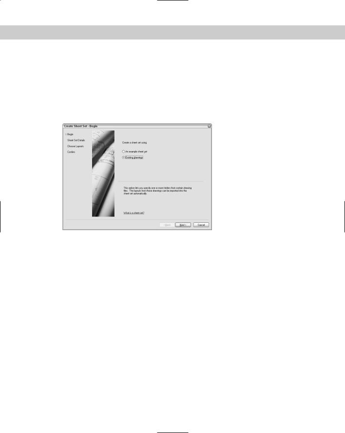
To create a sheet set, open the Sheet Set Manager and choose New Sheet Set from the dropdown list at the top of the palette. The Create Sheet Set wizard opens with the Begin pane displayed, as shown in Figure 26-23.
Figure 26-23: The Create Sheet Set wizard helps you create sheet sets.
You can choose to use an example sheet set that you’ve already created or that comes with AutoCAD in order to use its structure. If you want to work with existing drawings, choose the Existing Drawings option. Then click Next.
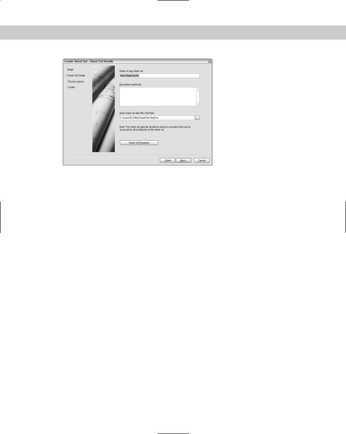
On the Sheet Set Details pane, shown in Figure 26-24, you name the sheet set, add an optional description, and specify the location of the file that contains the data for the sheet set. Sheet set files have a .dst filename extension and you can store them in the same folder as the sheets. Click the Ellipsis button to open the Browse for Sheet Set dialog box. There you can navigate to a folder or create a new folder by clicking the Create New Folder button. Then click Open to return to the wizard. You can click the Sheet Set Properties button at this point to specify various settings, but you have access to these properties from the Sheet Set Manager, so you can skip the properties at this stage. Then click Next.
On the Choose Layouts pane of the wizard, click Browse to add existing drawings that have layouts that you want to include in the sheet set. If you’ve created only model space drawings and want to create new sheets rather than including layouts from these drawings, you can skip this pane and click Next. However, if you have layouts that you’ve already set up, browse to a folder and click OK. You can continue to click Browse and add more folders if you want. You can then uncheck certain folders if you don’t want to include them.
Chapter 26 Keeping Control of Your Drawings |
813 |
Figure 26-24: You need to name the new sheet set and specify the location of its DST file.
Click Import Options to open the Import Options dialog box. Here you can decide if you want the sheet name to include the drawing name before the layout name. You can also choose to use your folder structure to create subsets. For example, if you have folders named Floor Plans, Elevations, and Sections, you could automatically create the subsets that you see in Figure 26-21. Click OK to close the Import Options dialog box and return to the wizard.
Click Next to display the Confirm pane of the wizard. This pane summarizes the choices you made in the wizard. If you want to change something click Back. Otherwise, click Finish. At this point, be aware that you can change everything later except the sheet set filename and location. Clicking Finish creates the DST file in the location you chose.
The Sheet Set Manager now displays your new sheet set. If you didn’t import any layouts, all you see is the Sheet List tab with the name of the Sheet Set.
Setting properties
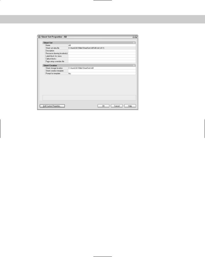
Before you go any further, you need to set the properties of your sheet set. These properties ensure that every aspect of the sheet set works the way you want it to. You can separately set properties for the sheet set, subsets, and individual sheets. To set sheet set properties, rightclick the name of the sheet set at the top of the Sheet List tab of the Sheet Set Manager and choose Properties to open the Sheet Set Properties dialog box, shown in Figure 26-25.
814 Part V Organizing and Managing Drawings
Figure 26-25: The Sheet Set Properties dialog box.
The Sheet Set Properties dialog box always contains the sheet set name and DST file location. Complete the rest of the properties as follows:
Description: Click this item and type a new description or edit an existing description.
Resource drawing locations: Click this item to display the Ellipsis button. Click the button and then click Add to browse to a folder containing drawings that you want to use for your sheets. Click Open and then click OK to return to the Sheet Properties dialog box. You can add more than one location. These drawings contain model space content that you want to place on layouts for your sheets. For easy organization, create a Resources folder inside the sheet set folder and place your drawings there. The locations that you enter here appear on the Resource Drawings tab of the Sheet Set Manager.
Label block for views: A label block labels a view and usually includes the view name, view number, and scale. To choose a label block, click this item and click the Ellipsis button. In the Select Block dialog box, click the Ellipsis button to choose a drawing that contains the block you want. (If your block is in your template, choose AutoCAD Drawing Template [*.dwt] from the Files of Type drop-down list.) Click Open. If the drawing contains only that block (in other words, if the drawing is the block that you want to use), choose the Select the Drawing File as a Block option. If the drawing contains several blocks, use the Choose Blocks in the Drawing File option. You then see a list of the blocks in the drawing. Choose the block you want (you can choose only one label block) and click OK. If you want to use the automatic numbering and referencing feature of sheet sets, you need to set up this block as I explain later in this chapter in the “Setting up sheet set references” section. If you want different blocks for different subsets, or if you don’t use a label block, leave this item blank.
Callout blocks: Callout blocks point to other drawings. For example, on a floor plan, a callout block marks the location of a section view that is on another sheet. To choose a callout block, click this item and click the Ellipsis button. In the List of Blocks dialog box, click the Ellipsis button again. Then, in the Select Block dialog box, click the

Chapter 26 Keeping Control of Your Drawings |
815 |
Ellipsis button (again!) to choose a drawing that contains the blocks you want. (For a template, choose AutoCAD Drawing Template [*.dwt] from the Files of Type dropdown list.) Click Open. If the drawing contains only that block (in other words, if the
drawing is the block that you want to use), choose the Select the Drawing File as a Block option. If the drawing contains several blocks, use the Choose Blocks in the Drawing File option. You then see a list of the blocks in the drawing. You can choose multiple callout blocks, because many drawings contain variations of this type of block. Click OK twice to return to the Sheet Set Properties dialog box. If you want to use the automatic numbering and referencing feature of sheet sets, you need to set up this block
as I explain later in this chapter in the “Setting up sheet set references” section. If you want different blocks for different subsets, or if you don’t use callout blocks, leave this item blank.
Page setup overrides file: You may want to override page setups (which I explain in Chapter 17) if you imported layouts with varying setups or if you ever need to plot the sheet set using different settings or a different plotter. You save these page setups in a template. Click this item, click the Ellipsis button that appears, choose a template, and click Open. You can create this template later and then go back and specify it.
Sheet storage creation: This folder defines where sheets are stored. If you didn’t specify this location when you created the sheet set, click this item, click the Ellipsis button, choose a folder, and click Open. Note that if the sheet set already contains sheets, changing this location doesn’t move existing sheets; it only affects the location of new sheets that you create.
Sheet creation template: Click this item and then the Ellipsis button. Then click the Ellipsis button in the Select Layout as Sheet Template dialog box. Choose a template (or a drawing or standards file) and click Open. You can then click a layout in the template. Click OK.
Caution |
If you want to use the automatic numbering and referencing features of sheet sets, don’t cre- |
|
ate any sheets before you’ve set up this template. |
Prompt for template: If you want your sheets to automatically use the template, this item should be No. If you sometimes vary your templates, change this item to Yes so that you can choose a different template when you want.
You can create custom properties. You create custom properties to automatically insert text in your title block, using AutoCAD’s field feature. After you create these properties, they become fields that you can insert. (See Chapter 13 for a discussion of fields.) A custom property can apply to a sheet set or an individual sheet. Common sheet-set custom properties are client name, project name, or project address. A typical sheet custom property would be the drawer’s or proofer’s initials, if more than one person works on the sheets in the sheet set.
To add custom properties, click the Edit Custom Properties button. In the Custom Properties dialog box, click Add. Then enter a name and a default value, and choose whether the property is for a sheet or a sheet set. (Adding a default value helps you test the fields when you set up your titleblock.) Click OK. Continue to click Add and define custom properties. When you’re done, click OK to return to the Sheet Set Properties dialog box.
When you finish setting your sheet-set properties, click OK to return to the Sheet Set Manager and your drawing.

816 Part V Organizing and Managing Drawings
Creating subsets
Subsets are categories that you can use to help your organize your sheets. They may or may not have corresponding folders where you keep sheets. To create a subset, right-click the sheet-set name and choose New Subset. In the Subset Properties dialog box, name the subset and specify the location of the sheet drawings files for that subset as well as the template. The default location for both is the same as for the sheet set.
After you’ve created subsets, you can change their properties by right-clicking any subset and choosing Properties from the shortcut menu.
When you create your sheets, you can set sheet properties in the same way, by right-clicking and choosing Properties.
Setting up sheet-set references
One of the more exciting features of sheet sets is the ability to automate the filling in of text in the title block, as well as the numbering of sheets, title blocks, and callout blocks. However, this feature is also fairly complex. You can omit this feature and still get significant benefits from sheet sets, such as the ability to plot the entire sheet set all at once and automate the creation of viewports. In this section, I explain how to configure the label and callout blocks so that the automation features work properly. If you don’t want to use these features, you can skip this section.
The secret of this feature is the use of fields, which I cover in Chapter 13. You can use the fields in two ways:
Place the fields in Mtext, which you insert in your title block, label block, and callout blocks.
Place the fields using attributes that you associate with these blocks. I cover attributes and blocks in Chapter 18.
|
The advantage of using attributes is that text cannot easily be changed. If you’re a CAD |
|
Manager and want to reduce errors, you might choose to use attributes. Of course, if you |
|
already use attributes, you might find it simpler to continue to use them. |
|
On the other hand, you might want the increased flexibility and simplicity of Mtext, especially |
|
if you don’t currently use attributes. One of the reasons for using attributes is to place text; |
|
using Mtext with fields works very well to specify text placement. |
|
Configuring titleblock text |
|
There are many ways of creating a titleblock. In this section, I assume that you have a tem- |
|
plate that contains a titleblock that you’ve inserted on a layout. Of course, this template also |
|
contains your text styles, table styles, dimension styles, layers, and so on. |
Tip |
To configure your template, don’t open it directly. Instead, create a new sheet in your sheet |
|
set. This sheet will automatically be based on the template you specified in the Sheet Set |
|
Properties dialog box. When you finish configuring this sheet, you will save it as a template. |
|
To create the sheet, right-click the sheet-set name and choose New Sheet. Give the sheet a |
|
name that indicates that it will become a template, such as WillBeTemplate. This tech- |
|
nique allows you to test your fields as you work, because the sheet is part of the sheet set |
|
(unlike a template that you open directly). Thanks to Heidi Hewett of Autodesk for this tip. |

Chapter 26 Keeping Control of Your Drawings |
817 |
Tip
Note
At this point, you should look at your titleblock and determine any custom properties that you need, as I explained in the previous section. You should set up these properties before you go on.
The new sheet appears on the Sheet List tab of the Sheet Set Manager. Double-click the sheet to open it. You should now see your template with its titleblock. If the titleblock text is part of a block, whether Mtext or attributes, explode the titleblock.
Don’t try to edit attributes or blocks using the Block Attribute Manager (BATTMAN command) or the REFEDIT command, because the existing block’s text will not be updated with the new field values. Instead, explode the block, change the text to fields, and redefine the block. Thanks to Heidi Hewett of Autodesk for this tip.
Double-click the Mtext or attribute text to open the Multiline Text Editor or the Edit Attribute Definition dialog box. To replace the text with a field, follow these steps:
1.Select the text.
2.Right-click and choose Insert Field to open the Field dialog box.
3.Choose one of the following fields:
•CurrentSheetCustom: Custom properties that apply to individual sheets
•CurrentSheetNumber: The sheet number
•CurrentSheetNumberandTitle: The sheet number and name
•CurrentSheetSet: The name of the sheet set
•CurrentSheetSetCustom: Custom properties that apply to the sheet set
•CurrentSheetSetDescription: The sheet set description that you specified
•CurrentSheetSetSubSet: The name of the subset that the current sheet is in
•CurrentSheetTitle: The name of the sheet
•CreateDate: Places the current date. (Unlike the Date field, this field doesn’t update each time you open or regenerate the drawing.)
4.Choose a format from the Format list.
5.If you chose one of the custom fields, choose the specific field from the Custom Property Name drop-down list.
You should immediately see the value of your field either in your drawing or in the Edit Attribute Definition dialog box.
6.Click OK. Repeat Steps 1 through 5 to continue to add fields for the entire titleblock in this way.
7.Choose File Save As. From the Files of Type drop-down list, choose AutoCAD Drawing Template (*.dwt). Specify the location that you want for your sheet set template. (The Template folder has a SheetSets subfolder that you can use.) Click Save. Usually, you’re overwriting an existing template, so confirm the overwrite. Enter a description in the Template Description dialog box and click OK.

818 Part V Organizing and Managing Drawings
8.You can now delete the sheet from the sheet set. Deleting a sheet doesn’t delete the drawing. Right-click the sheet and choose Remove Sheet. Click OK to confirm. The drawing is still open.
9.The template is now open on your screen. If you exploded the titleblock, you need to redefine the block. If you’re using attributes for your text, you need to include the text as attribute definitions.
10.Select all the objects in your titleblock. Choose Make Block from the Draw toolbar. In the Block Definition dialog box, enter the name of your titleblock block in the Name text box. Click OK.
You can now immediately define label and callout blocks directly in the template. If you don’t need these blocks, skip the next section and close the template.
Configuring label and callout blocks
Label blocks can automatically display the sheet number, sheet name, and scale. Callout blocks can automatically display the view number (often called the detail number) as well as the sheet number. In addition, callout blocks can contain a hyperlink to the view that they reference so that users can immediately display that view. You can see an example of label and callout blocks in Figure 26-27.
To set up your label and callout blocks, the simplest solution is probably to work directly in the template. When you’re done, you’ll delete the inserted blocks to keep only their definitions. If you want to store these blocks in a separate drawing, open the drawing. Follow these steps:
1.Choose Insert Block and choose your label block. Click OK and specify any insertion point.
2.Explode the block.
3.Double-click the text that contains the view number. (This is often called the detail number.) Either the Multiline Text Editor or the Enhanced Attribute Editor opens.
4.Select the text. (In the Enhanced Attribute Editor, select the text in the Value text box. Right-click and choose Insert Field. The Field dialog box opens.
5.From the Field Names list, choose SheetSetPlaceholder. From the Placeholder Type list, choose View Number.
6.Repeat Steps 3 through 5 for the view name and the view scale, using the ViewTitle and the ViewportScale types of the SheetSetPlaceholder field, respectively.
7.To redefine the block, select all the objects, choose Make Block from the Draw toolbar, and type the title block name in the Name text box. When you insert the label block, it will automatically be inserted into the drawing with its insertion point at the lower-left corner of the view, so define the base point of the block slightly above the block’s left edge. Click OK and click Yes to confirm the redefinition of the block.
Note |
If your text is composed of attributes, choose Modify Object Attributes Block Attribute |
|
Manager to open the Block Attribute Manager. Choose each field, click Edit, check the Preset |
|
check box, and click OK twice to return to your drawing. You want attributes that are fields to |
|
be preset because you’ll define their value using the Sheet Set Manager; you don’t want the |
|
Enter Attributes dialog box to pop up to ask for a value whenever you insert a title block. |

Chapter 26 Keeping Control of Your Drawings |
819 |
8.If you didn’t choose the Delete option in the Block Definition dialog box, delete the block. The block definition stays in the template’s database and will be available to any drawing that you base on that template.
9.Repeat Steps 1 through 9 for your callout blocks. For these blocks you use the SheetSetPlaceholder field with the ViewNumber and SheetNumber field types. However, for callout blocks, be sure to check the Associate Hyperlink checkbox in the Field dialog box, so that the callout bubble will link to the view (detail) that it references.
10.Save the template and close it.
You’re now ready to use your sheet set.
Adding and managing sheets
After you’ve configured your sheet set properties you’re ready to use your sheet set. The first step is to specify the value of any custom properties that you have defined so that they’ll appear in your titleblock text property. On the Sheet List tab, right-click the sheet-set name and choose Properties. Click Edit Custom Properties and set the values that you want.
You can now add sheets. Each sheet will be a separate drawing with one layout tab. To add a sheet, follow these steps:
1.Display the Sheet List tab of the Sheet Set Manager.
2.Right-click the sheet set name and choose New Sheet.
3.In the New Sheet dialog box, give the sheet a number and a name.
4.The name of the drawing is automatically completed, using both the number and the name of the sheet.
Tip |
You can delete the number in front of the sheet name. Otherwise, if you change the order of |
|
your sheets, the drawing filename doesn’t change, so your filenames will get out of sync. |
5.Click OK. The new sheet appears on the Sheet List tab.
6.If you created sheet properties, right-click the sheet name and choose Properties. Change the values of any custom properties that are specific for that sheet.
To organize your sheets, you can create subsets. A subset is just an organizational tool, although you can create a folder structure that matches your subsets. You can also assign different templates to sheets in different subsets. To add a subset, right-click the sheet set name and choose New Subset. You can also right-click an existing subset and choose New Subset to create a nested subset. In the Subset Properties dialog box, name the subset. You can also assign a template and folder location. Click OK.
On the Sheet List tab, you can also do the following with sheets:
Move sheets: You can place sheets in a different order by dragging them.
Remove sheets: Right-click any sheet and choose Remove Sheet. You can also select multiple sheets to remove all the selected sheets. Click OK to confirm.
Change a sheet’s name and number: Right-click a sheet and choose Rename and Renumber. Type a new number, a new name, or both and click OK. Note that renumbering a sheet doesn’t change its order on the Sheet List. Two sheets can have the same number. You can use any numbering system you want.
820 Part V Organizing and Managing Drawings
Change sheet properties: Right-click a sheet and choose Properties. Make any changes that you want in the Sheet Properties dialog box and click OK.
Import a sheet: You can create a sheet by importing a layout tab of an existing drawing. On the Sheet List tab, right-click the sheet set name and choose Import Layout as Sheet. In the Import Layouts as Sheets dialog box, click the Ellipsis button. Navigate to a drawing and click Open. Then choose the layouts in that drawing that you want to import.
Click OK.
Note To import a layout as a sheet, you must have displayed a layout tab in that drawing; otherwise you get a message that the drawing does not contain any initialized layouts. To remedy the situation, open the drawing, click the layout tab, and save the drawing. Then close the drawing and you’ll be able to import the layout into your sheet set.
On the
CD-ROM
The drawings and files used in the following Step-by-Step exercise on creating and configuring a sheet set, ab26-f-1.dwg, ab26-f-2.dwg, ab26-f-3.dwg, and ab26-f.dwt, are in the Drawings folder on the CD-ROM.
STEP-BY-STEP: Creating and configuring a sheet set
Note: This is a long exercise. You should leave yourself 45 to 60 minutes to complete it.
1.Open Windows Explorer. (Right-click the Windows Start button and choose Explore.) In the folder pane, locate and click the AutoCAD Bible folder that you created for the exercises in this book. From the menu, choose File New Folder and name the new folder AB Sheet Set.
2.Click the new AB Sheet Set folder and again choose File New Folder. Name the new folder AB Resource Drawings.
3.Copy ab26-f-1.dwg, ab26-f-2.dwg, ab26-f-3.dwg, and ab26-f.dwt (a template file) from the CD-ROM of this book to the AB Resource Drawings folder.
4.Open a new drawing based on any template. (You need a drawing open to create a new sheet set, although not to open an existing one.)
5.Choose Sheet Set Manager from the Standard toolbar. From the drop-down list at the top, choose New Sheet Set to open the Create Sheet Set wizard.
6.On the Begin pane, choose Existing Drawings and click Next.
7.In the Name of New Sheet Set text box, type ab26-f. In the Description text box, type AB Residence, size A. (You wouldn’t normally use size A sheets for architectural drawings, but using this size enables you to print the sheets on your printer if you don’t have a plotter available.) In the Store Sheet Set Data File (.dst) Here box, click the Ellipsis button and navigate to the AutoCAD Bible\AB Sheet Set folder that you created in Step 1. Click Open and then click Next.
8.On the Choose Layouts pane, click Next. You’re going to create the sheets from scratch rather than import them. (You will use the existing drawings as resource drawings for the sheets, but you won’t use them as the sheets themselves.)
9.On the Confirm pane, read the information. If it’s correct, click Finish. (Otherwise, click Back and make any corrections you want.)

Chapter 26 Keeping Control of Your Drawings |
821 |
10.Click the Sheet List tab of the Sheet Set Manager if it isn’t already on top. You should see your sheet set listed. Right-click the sheet set name and choose Properties from the shortcut menu.
11.In the Sheet Set Properties dialog box, set the following items:
•Resource drawing location: Click the Ellipsis button. Click Add. Navigate to the AB Resource Drawings folder that you created in Step 2 Click Open. Click OK to return to the Sheet Set Properties dialog box.
•Label block for views: Click the Ellipsis button. In the Select Block dialog box, click the Ellipsis button again. If necessary, choose AutoCAD Drawing Template (*.dwt) from the Files of Type drop-down list. Navigate to the AutoCAD Bible\ AB Sheet Set\AB Resource Drawings folder and choose ab26-f.dwt. Click Open. Choose the Choose Blocks in the Drawing File option. Choose the view label block. Click OK.
•Callout blocks: Click the Ellipsis button. In the List of Blocks dialog box, click Add. In the Select Block dialog box, click the Ellipsis button. If necessary, choose AutoCAD Drawing Template (*.dwt) from the Files of Type drop-down list. Navigate to the AutoCAD Bible\AB Sheet Set\AB Resource Drawings folder and choose ab26-f.dwt. Click Open. Choose the Choose Blocks in the Drawing File option. Choose the Callout button-left arrow block. Click OK twice.
•Sheet creation template: Click the Ellipsis button. In the Select Layout as Sheet Template dialog box, click the Ellipsis button. If necessary, choose AutoCAD Drawing Template (*.dwt) from the Files of Type drop-down list. Navigate to the
AutoCAD Bible\AB Sheet Set\AB Resource Drawings folder and choose ab26-f.dwt. Click Open. If the template contains more than one layout, choose the layout of the template that you want to use. Click OK.
12.Click Edit Custom Properties. Click Add. In the Add Custom Property dialog box, add a property called Project Name and a value of ProjectName. Choose the Sheet Set option and click OK. Add the following other custom properties:
•Project Address 1, with a value of ProjectAddress1, sheet set
•Project Address 2, with a value of ProjectAddress2, sheet set
•Drawn By, with a value of DB, sheet
•Checked By, with a value of CB, sheet
Click OK to close the Custom Properties dialog box. Click OK again to close the Sheet Set Properties dialog box and return to your drawing.
13.Right-click the sheet set name and choose New Subset. Type Floor Plans and click OK. Repeat this process to add subsets for Elevations and Sections.
14.To configure the titleblock text, right-click the sheet set name and choose New Sheet. Because you’ll later save this sheet as a template and then delete it, number it XX and name it WILL BE TEMPLATE. (This technique helps you confirm your fields.) Delete the XX from the front of the filename and click OK.
15.Double-click the new sheet to open it. You should see the template’s titleblock.

822 Part V Organizing and Managing Drawings
16.Double-click the text ProjectName to open the Multiline Text Editor. Select the text, right-click, and choose Insert Field. Choose Sheet Set from the Field Category drop-down list to filter the fields that you see on the Field Names list. Choose CurrentSheetSetCustom (check the field name carefully, because there are many similar fields), set the format to Title case, and choose Project Name from the Custom Property Name drop-down list. Click OK. You now see the text surrounded by the gray field box. Click OK to close the Multiline Text Editor. In the same way, set the following other fields:
•ProjectAddress1: CurrentSheetSetCustom, Title case, Project Address 1
•ProjectAddress2: CurrentSheetSetCustom, Title case, Project Address 1
•DB: (Drawn By) CurrentSheetCustom, Uppercase, Drawn By
•CB: (Checked By) CurrentSheetCustom, Uppercase, Checked By
* P-01: CurrentSheetNumber, Uppercase
You can now see the values of all the fields in the titleblock.
17.The layout tab takes on the name of the sheet, which is WILL BE TEMPLATE. Right-click the layout and choose Rename. Name the layout tab Titleblock.
18.Choose File Save As. From the Files of Type drop-down list, choose AutoCAD Drawing Template (*.dwt). Navigate to your AutoCAD Bible\AB Sheet Set\AB Resource Drawings folder. Name the template ab26-f.dwt. Click Yes to replace the existing template. Click OK to accept the description. (Because you have now changed the template, if you want to do the exercise again, recopy the template from the CD-ROM.)
19.You no longer need the WILL BE TEMPLATE sheet. Right-click the sheet and choose Remove Sheet. Click OK to confirm. (Removing the sheet does not remove the drawing or templates.)
20.The template is still open. Change the current layer to 0.
21.To configure the label and callout blocks, choose Insert Block from the Draw toolbar and choose the view label block from the Name drop-down list. Make sure that only the Insertion Specify On-Screen check box is checked and click OK. Pick any insertion point. The Enter Attributes dialog box opens. Click OK. (If the attribute prompts appear on the command line, press Enter until the command is completed.
22.In the same way, insert the callout bubble-left arrow block.
23.Select both blocks and click Explode on the Modify toolbar.
24.In the view label block, double-click the V# text inside the circle. The Edit Attribute Definition dialog box opens. Select the text in the Default text box. Right-click in the Default text box and choose Insert Field. In the Field dialog box, choose SheetSetPlaceholder as the Field Name and View Number as the Placeholder Type. (If you use view numbers that include letters, choose Uppercase as the Format.) Click OK twice to return to your drawing.
Note |
You don’t see the gray field box yet, because you haven’t yet inserted the attribute as part of |
|
a block. |

Chapter 26 Keeping Control of Your Drawings |
823 |
On the
CD-ROM
25.In the view label block, use the same procedure to add SheetSetPlaceholder fields for VIEWNAME (use the ViewTitle type and Title case format) and SCALE (use the ViewportScale type and choose the format you want).
26.Choose Make Block from the Draw toolbar. Type view label in the Name text box. Click the Pick Point button and pick an insertion point a little above the left side of the label block objects. Click the Select Objects button and select all the objects in the view label block. Choose the Delete option on the Objects section. Click OK.
27.Choose Modify Object Attributes Block Attribute Manager. Choose view label from the Block drop-down list. Choose the first attribute tag, click Edit, check the Preset check box, and click OK. Do the same with the other two tags and click OK to return to your drawing.
28.Repeat Steps 24 through 27 for the callout bubble-left arrow block. For the top text, use the ViewNumber placeholder type. For the bottom text, use the SheetNumber placeholder type. This time, be sure to check the Associate Hyperlink check box in the Field dialog box.
29.Make sure both blocks have been deleted. Then save and close the template.
30.Before you create new sheets, specify the values of the sheet set level custom properties. Right-click the sheet name on the Sheet List tab of the Sheet Set Manager and choose Properties. For Project Name, enter AB Residence. For Project Address 1, enter any address. For Project Address 2, enter any city, state, and ZIP or postal code. Click OK to close the dialog box.
31.On the Sheet List tab of the Sheet Set Manager, right-click the Floor Plans subset and choose New Sheet. Number the new sheet 1 and name it Basement Floor Plan. Delete the number 1 from the filename and click OK. In the same way, create a sheet 2 named 1st Floor Plan and a sheet 3 named 2nd Floor Plan.
32.In the same way add four new sheets to the Elevations subset:
•4: East Elevation
•5: North Elevation
•6: West Elevation
•7: South Elevation
33.In the same way, add two new sheets to the Sections subset: a sheet 8 called Internal Sections and a sheet 9 called External Sections.
34.Right-click each sheet that you’ve created and choose Properties. Change the values for the DB and CB sheet properties to any initials.
35.Leave AutoCAD and the Sheet Set Manager open for the next Step-by-Step exercise.
The drawings and sheet set data file that you created in the exercise are in the Results folder on the AutoCAD 2005 and AutoCAD LT 2005 Bible CD-ROM.
Using a sheet set
When your sheet set is configured and you’ve created your sheets, you’re ready to use your sheet set. You can create viewports on your sheets, insert callout blocks, plot or publish sheets, archive and eTransmit sheets, and create a table that lists all the sheets.

824 Part V Organizing and Managing Drawings
Creating viewports from named views
A major feature of a sheet set is the ability to create viewports on your sheets. You do this by creating named views in model space in your resource drawings. Then you place the view onto a layout to create a viewport. (For information on named views, see Chapter 8. For coverage of viewports, see Chapter 17.) When you place the view, you can specify the scale that you need.
If you don’t already have the named view that you need, click the Resource Drawings tab and double-click the drawing containing the content that you need. This opens the drawing. (If necessary, click the plus sign next to the resource location to display the available drawings.) Click the Model tab, define the named view, then save and close the drawing.
The Resource Drawings tab now lists the named view under the drawing. (Again, you may have to click the plus sign next to the drawing to display the view.)
To create a viewport based on a named view, follow these steps:
1.Click the Sheet List tab. Double-click the sheet on which you want to place a viewport, to open the drawing with the layout displayed.
2.Click the Resource Drawings tab.
3.Right-click the named view that you want to use and choose Place on Sheet.
4.Move the cursor onto the drawing area. The command line displays the Specify insertion point: prompt, and you can see the view on the layout. AutoCAD calculates a standard scale based on the size of the layout and the size of the view.
5.To change the scale, right-click in the drawing area. A list of scales appears. Choose the scale that you want.
6.Click to specify the insertion point that you want and place the viewport. If you’ve specified a label block, the block automatically appears with its insertion point at the lower-left corner of the view.
Use this procedure to place viewports on all your sheets. Your views now appear on the View List tab. If you want to place callout or label blocks that use the ViewNumber field, you need to number these views. Right-click a view on the View List tab and choose Rename and Renumber. Enter a number and a name and click OK. To see the result in an existing field, regenerate the drawing to update the fields.
Inserting callout blocks
If you’ve set up callout blocks, as I describe in the “Configuring title and callout blocks” section earlier in this chapter, now is the time to place them. A callout block references another sheet that contains a detail or a different view. Follow these steps:
1.On the Sheet List tab of the Sheet Set Manager, double-click the sheet on which you want to place the callout block, to open the layout.
2.Click the View List tab, which contains all the viewports that you have on your layouts, and right-click the view that you want to reference. Choose Place Callout Block and choose the block. (If you see a Select Blocks submenu item, choose it, choose the block that you want, and click OK to select the block that you want to use. This makes the block available on the menu. Then right-click the view again, choose Place Callout Block and choose the block.)
3.At the prompt, pick an insertion point to place the block. The block should display the correct view (detail) and sheet number.

Chapter 26 Keeping Control of Your Drawings |
825 |
Plotting and publishing
Automation of plotting and publishing is one of the advantages of sheet sets. You can plot or publish an entire sheet set or just part of it — directly from the Sheet Set Manager.
To plot the entire sheet set, click the sheet set name and choose Publish Publish to Plotter. Your sheet set plots according to the settings in the template. To apply page
setup overrides, choose Publish Using Page Setup Override.
To publish the sheet set, click the sheet set name and choose Publish to DWF. For more information about the PUBLISH command, see Chapter 28.
On the same menu, you have options to add a plot stamp, manage plot setups, and open the PUBLISH dialog box.
To plot or publish a subset or sheet, right-click the subset or sheet and use the options on the shortcut menu.
You can create selection sets of sheets and save them. Then you can plot or publish the selection set of sheets. To create a selection set of sheets, select the sheets that you want to include and click Sheet Selections Create. Name the selection set and click OK.
After that, you can choose the selection set from the Sheet Selections drop-down list to select the sheets you need. Then you can choose to plot or publish them.
Archiving and eTransmitting sheet sets
Archive your sheets sets to save them in ZIP format (by default). You can use the ZIP file for transmittal or backup purposes. (For more information about the archiving process, see the discussion on eTransmitting drawings in Chapter 28.) To archive a sheet set, follow these steps:
1.Right-click the sheet-set name and choose Archive.
2.In the Archive a Sheet Set dialog box, you can add notes that will go in the archive report, use the tabs to review the files that will be included, view the archive report, and modify current archive settings. Then click OK.
3.Choose a location for the archive file and click Save.
You create a transmittal when you want to e-mail your sheet set along with all necessary depending drawings and files. I cover eTransmitting drawings in Chapter 28. To eTransmit a sheet set, follow these steps:
1.Right-click the sheet-set name and choose eTransmit.
2.In the Create a Transmittal dialog box, you can add notes, use the tabs to review the files that will be included, view the archive report, and choose a transmittal setup that you’ve saved. Click OK.
3.Choose a location for the file and click Save.
Creating a list of sheets
A sheet set often has a cover page that contains a table of contents. Using AutoCAD’s new table feature, you can automatically generate a table that lists all the sheets in the sheet set. To create a table listing the sheets, follow these steps:
1.Create a new sheet. You can number it sheet 1 or sheet 0.
2.Double-click the sheet to open its drawing.
826 Part V Organizing and Managing Drawings
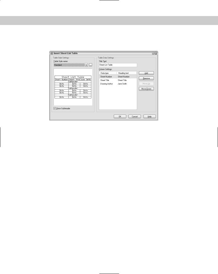
3.Right-click the sheet-set name and choose Insert Sheet Set Table to open the Insert Sheet List Table dialog box, shown in Figure 26-26.
Figure 26-26: Use the Insert Sheet List Table dialog box to create a table that lists all the sheets in your sheet set.
4.From the Table Style Name drop-down list, choose any table style that you’ve saved in your template. You can click the Ellipsis button to open the Table Style dialog box and define a table style.
5.Check the Show Subheader check box if you want to show your sheets divided by subsets.
6.In the Title Text text box, enter a name to appear as the title of the table. You may want to use the name of the sheet set here, instead of the default text.
7.In the Column Settings section, you specify what data you want to show and how you want to title each column. On the left, you can choose the data from the drop-down lists. On the right, you can change the text. For example, for the Sheet Title item, you may want the title to appear as “Sheet Name.” Click Add to add a new column; click Remove to remove a column. You can also change the order of the columns.
8.Click OK.
9.A message appears explaining what happens if you manually make changes in the table. (The changes are lost when you update the table.) Click OK.
10.At the Specify insertion point: prompt, pick a location for the table on your cover sheet.
If you make any changes in your sheet set, such as adding or renumbering sheets, you should update the table. Select the table by clicking on any outside border, right-click, and choose Update Sheet List Table.
Chapter 26 Keeping Control of Your Drawings |
827 |
On the
CD-ROM
The drawings and files used in the following Step-by-Step exercise on creating and configuring a sheet set, ab26-f-1.dwg, ab26-f-2.dwg, ab26-f-3.dwg, are in the Drawings folder on the CD-ROM. The ab26-f.dwt file is in the Results folder. (It’s called ab26-f.dwt after exercise.dwt because it contains the results of the previous exercise. Ideally, you should do the previous exercise and use the template that you saved in that exercise.) If you use the template from the Results folder, rename it to ab26-f.dwt.
STEP-BY-STEP: Using a Sheet Set
1.You should do the previous exercise before doing this exercise to set up and configure your sheet set and the blocks. If the Sheet Set Manager is not open, choose Sheet Set Manager from the Standard toolbar, click Open, and open the ab26-f sheet set from the AutoCAD Bible\AB Sheet Set folder.
2.Click the Resource Drawings tab of the Sheet Set Manager. Click the plus sign next to the folder name at the top to display the list of the three drawings in the AB Resource Drawings folder. Again, click the plus sign next to each drawing to display their model space named views.
3.Click the View List tab. Double-click view 1 - Basement Floor Plan. You see the titleblock displayed with all the titleblock fields completed.
4.Change the current layer to viewport.
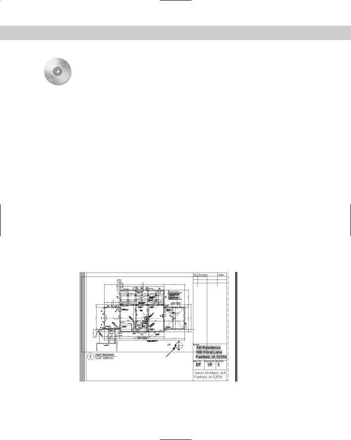
5.Click the Resource Drawings tab again. Right-click Floor - Basement and choose Place on Sheet. Move the cursor onto the drawing area. (You may want to auto-hide the Sheet Set Manager at this point.) Right-click and choose 1/16"=1'. Place the viewport all the way to the left of the layout. (The view doesn’t fit perfectly, but that’s okay for this exercise.) The result should look like Figure 26-27, except without the callout block. (If you want, continue to place the floor-plan views on the floor-plan sheets, matching the 1st and 2nd floor views to the 1st and 2nd floor sheets. You can also do the same for the four elevation views.)
1
Figure 26-27: The basement floor plan.