


Chapter 1 Starting to Draw |
9 |
AutoCAD LT Text window. You can scroll back through previous commands. Press F2 again to close the window. You can also simply hide the Text window by clicking in the AutoCAD or AutoCAD LT window for easy access to the Text window later from the Windows taskbar.
The status bar
At the very bottom of the screen is the status bar (refer to Figure 1-2). At the left are the X,Y coordinates. As you move your mouse, these coordinates change. (If they don’t change, click them and move your mouse again.) The status bar also sports several buttons that I explain later in this book.
At the right side of the status bar is a small down arrow. Click it to open the status bar menu. This menu determines which buttons appear on the status bar. If you don’t use a certain button, choose it on the menu to remove its checkmark and make it disappear. You can always go back and choose the item again to redisplay the button. Also at the right side of the status bar is the new Communication Center icon. (See Chapter 26 for details.)
In AutoCAD only, you can use the Express Tools FULLSCREEN command to hide the title bar, menu, and status bar, leaving more room for the drawing area. To return to the regular display, type fullscreen on the command line and press Enter.
Cross- |
For information about installing the Express Tools, see Appendix A. |
Reference |
|
Creating Your First Drawing
You are now almost ready to draw your first lines. But first take a minute to get accustomed to using the toolbars to give AutoCAD or AutoCAD LT a command.
Toolbars
On the Draw toolbar, move the mouse cursor over the first button. You see a tooltip that says Line, as shown in Figure 1-4. Also notice the status bar, which tells you that this button creates straight-line segments.
Tip If you inadvertently start a command that you don’t want, press Esc. The command-line prompt (Command:) returns.
Creating a new folder
For your work with this book, you should create a new folder so that you can save your exercise drawings where they won’t get mixed up with other drawings. The following directions leave it up to you where to create this new folder. Each computer system is organized differently. If you aren’t sure what to do, choose the drive (not the folder) where AutoCAD or AutoCAD LT is installed and create a new folder there.
Caution |
I do not recommend creating a subfolder in the AutoCAD 2005 or AutoCAD LT 2005 folder. |
|
This folder contains the files that make up the program. If you keep your drawings here, it is too |
|
easy to make a mistake and delete necessary program files. Many people create a subfolder in |
|
the My Documents folder. |
10 |
Part I AutoCAD and AutoCAD LT Basics |
Figure 1-4: Moving the cursor over the Line button displays a tooltip.
STEP-BY-STEP: Creating a New Folder
1.Move the mouse cursor down to the taskbar at the bottom of your screen and rightclick Start.
2.Choose Explore.
3.On the left pane of Windows Explorer, click the drive where you want to create the new folder. If you don’t know where to create the folder, choose the drive where AutoCAD or AutoCAD LT is installed. If you’re on a network, choose the drive that represents your computer.
4.If you want to make a subfolder (a folder within a folder), choose the folder where you want to create the subfolder.
5.From the Explorer menu, choose File New Folder. A new, highlighted folder, named New Folder, appears in the right pane. You may have to scroll down to see it.
6.Type AutoCAD Bible for the folder name and press Enter. (If you did the exercises from a previous edition of this book, such as AutoCAD 2004 Bible, and you already have a folder named AutoCAD Bible, first rename the original folder to something such as
ACAD2004Bible.)
Save all drawings that you create for this book in your AutoCAD Bible folder.
Caution |
Creating a folder for your drawings as described in the previous steps is essential before you |
|
go on to exercises in the rest of this book. |

Chapter 1 Starting to Draw |
11 |
Creating your first drawing
In this Step-by-Step exercise, you draw a window. You use a number of drawing and editing techniques to give you a feel for how AutoCAD and AutoCAD LT work. These techniques are explained in detail throughout the book. When you finish drawing the window, you add some dimensions and then print (or plot) the drawing.
For this exercise, simply follow the instructions exactly. When you type the X and Y coordinates (shown in bold), type the first number, a comma, and then the second number, with no spaces between them.
Tip Don’t worry if you don’t understand everything you’re doing. It all becomes clear as you progress through this book. If you haven’t read the Preface, now is a good time to go back and read the part that explains how to follow the exercises.
Follow the prompts shown next. As explained in the Preface, you type what appears in bold. Instructions to you in command sections appear in italics.
On the |
The drawing (template) that you need for the following Step-by-Step exercise on drawing a |
CD-ROM |
window, ab01-a.dwt, is in the Drawings folder of the AutoCAD 2005 and AutoCAD LT 2005 |
|
Bible CD-ROM. |
STEP-BY-STEP: Drawing a Window
1.Start AutoCAD or AutoCAD LT.
You see the new drawing. (If you are prompted for a template, skip to Step 2, the third sentence.)
2.Choose File New. The Select Template dialog box opens. Navigate to the Drawings folder of the CD-ROM of this book, choose ab01-a.dwt, and click Open. You see a blank drawing. (I explain more about templates and opening drawings in Chapter 2.)
3.To save the drawing, click Save on the Standard toolbar (refer to Figure 1-2 to find
this toolbar). In the Save Drawing As dialog box, use the Save In drop-down list to navigate to the AutoCAD Bible folder that you created in the previous exercise. Type ab01-01 in the File Name text box and click Save. This name means that this is the first drawing from Chapter 1 of the AutoCAD 2005 and AutoCAD LT 2005 Bible. (I go into more detail about saving a drawing in the next section of this chapter.)
4.From the Layer Control drop-down list on the Layers toolbar (refer to Figure 1-2 to find this toolbar), click the down arrow and choose WINDOW. (Layers allow you to organize your drawing; I cover them in detail in Chapter 11.) Anything you draw will now be on the WINDOW layer.
5.With your left mouse button (also called the pick button), choose Rectangle from the Draw toolbar (refer to Figure 1-2 to find this toolbar). (Using toolbars is only
one way to give AutoCAD and AutoCAD LT commands. I explain other ways in Chapter 3. You can find more about drawing lines and rectangles in Chapter 6.)
6.Follow these prompts to draw a rectangle that is 3'8" wide and 6'8" high:
Command: _rectang
Specify first corner point or [Chamfer/Elevation/Fillet/Thickness/ Width]: 0,0
Specify other corner point or [Dimensions]: 3’8”,6’8”

12 |
Part I AutoCAD and AutoCAD LT Basics |
7. To create a second rectangle inside the first one, choose Offset from the Modify toolbar, (refer to Figure 1-2 to find this toolbar) following these prompts:
Specify offset distance or [Through] <Through>: 4
Select object to offset or <exit>: Click the rectangle to select it.
Specify point on side to offset: Click anywhere inside the rectangle.
Select object to offset or <exit>: (Press Enter.)
8.You can draw from geometric points on objects such as endpoints and midpoints. (I explain how to specify coordinates in Chapter 4.) To draw a line between the midpoints of the inner rectangle, choose Line from the Draw toolbar and follow these prompts:
Specify first point: Press and hold the Shift key and right-click. From the shortcut menu that opens, choose Midpoint. Then click (with the left mouse button) the left side of the inner rectangle.
Specify next point or [Undo]: Press and hold the Shift key and rightclick. From the shortcut menu that opens, choose Midpoint. Then click
(with the left mouse button) the right side of the inner rectangle.
Specify next point or [Undo]: (Press Enter.)
Your drawing should now look like Figure 1-5. (Your window should be green.)
Figure 1-5: The beginning of a window.
9.You will now draw a construction line to help you find the starting point for the top half of the window. From the Draw toolbar, choose Line. Follow these prompts:
Specify first point: Press Shift and right-click. Choose Endpoint from the shortcut menu. Pick the left endpoint of the last line you drew.
Specify next point or [Undo]: @4,4 . (This notation specifies that the endpoint of the line is 4 units above and to the right of the first point. Chapter 4 explains more about specifying coordinates in this manner.)
Specify next point or [Undo]: .

Chapter 1 Starting to Draw |
13 |
10.Again choose Rectangle from the Draw toolbar. Follow these prompts:
Specify first corner point or [Chamfer/Elevation/Fillet/Thickness/ Width]: Press Shift and right-click. Choose Endpoint and pick the final endpoint of the diagonal line you just drew.
Specify other corner point or [Dimensions]: @2’4”,2’4”
11.Choose Erase from the Modify toolbar. At the Select objects: prompt, pick the
short diagonal construction line that you drew in Step 9. The Select objects: prompt appears again. Press Enter to end the command. (Chapter 9 explains the ERASE command as well as other simple editing commands.)
12.Click the ORTHO button on the status bar at the bottom of the drawing area. The ORTHO feature constricts drawing to right angles — horizontal or vertical. (You can find more about ORTHO in Chapter 4.)
13.To finish the bottom of the window, choose Line from the Draw toolbar. Follow these prompts:
Specify first point: 8”,3’4”
Specify next point or [Undo]: Move the mouse cursor down from the
start point of the line, which is shown as a temporary drag line. Then type the following length of the line. 2’8-7/16
Specify next point or [Undo]: Move the cursor horizontally to the right and type 28 .
Specify next point or [Close/Undo]: Now try entering the distance
using decimal notation, instead of feet and inches. Move the cursor up and type 32.4375
Specify next point or [Close/Undo]:
14.To draw shutters, first change the layer. Click the Layer Control drop-down list on the Layers toolbar, and choose EXWALL.
15.Choose Line from the Draw toolbar. Follow the prompts:
Specify first point: Press Shift and right-click. Choose Endpoint
from the shortcut menu. Click the upper-left corner of the window. Specify next point or [Undo]: Move the cursor to the left. Type 1’6”
Specify next point or [Undo]: Move the cursor down. Type 6’8” Specify next point or [Close/Undo]: 0,0
Specify next point or [Close/Undo]:
16.To draw the opposite shutter, you’ll mirror the first shutter that you just drew. (I cover the MIRROR command and many other editing commands in Chapter 10.) Choose Mirror from the Modify toolbar and follow these prompts:
Select objects: Click the three lines that make up the shutter.
Select objects:
Specify first point of mirror line: _Press Shift and right-click. Choose Midpoint from the shortcut menu.
mid of Pick the top horizontal line of the window.
Specify second point of mirror line: The ORTHO button should still be indented. (If not, click it.) Move the cursor downward and pick any
point to specify a vertical mirror line.
Delete source objects? [Yes/No] <N>:
Your window is now complete and should look like Figure 1-6.

14 |
Part I AutoCAD and AutoCAD LT Basics |
Figure 1-6: The completed window.
17.To add a dimension to the bottom of the window, you should first change the layer. From the Layer Control drop-down list on the Layers toolbar, choose DIMENSION. (Chapters 14 and 15 explain how to format and create all types of dimensions.)
18.To place the dimension, choose Dimension Linear. Follow the prompts.
Specify first extension line origin or <select object>: (Pressing Enter lets you select an object to dimension.)
Select object to dimension: Pick the bottom horizontal line of the window (the bottom of the rectangle).
Specify dimension line location or [Mtext/Text/Angle/Horizontal/Vertical/Rotated]: Move the cursor down until the dimension is nicely spaced below the window. Click to place the dimension line.
Note If you don’t have enough room to place the dimension below the window, click the down arrow of the vertical scrollbar as necessary. I explain additional techniques for changing the view of your drawing in Chapter 8.
19.Click Save on the Standard toolbar to save your work.
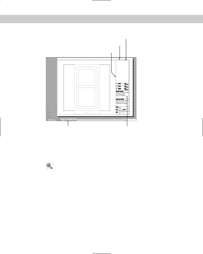
20.To prepare for printing, click the layout tab, A Title Block-Landscape. You see the window inside a title block and border, as shown in Figure 1-7. This title block and border comes with the template to help you easily prepare the drawing for printing. (Chapter 17 explains how to lay out and print/plot a drawing.)
21.To set the scale for printing, click the magenta viewport border (labeled in Figure 1-7). Choose Tools Properties. In the Properties palette, click the Standard Scale item. Click the down arrow that appears to the right of this item and choose 1"=1'. Click the Properties palette’s close button at the top of the palette. (I explain more about scales in Chapter 5.)
Chapter 1 Starting to Draw |
15 |
Title border
Page border
Viewport border
Layout tab |
Title block |
Figure 1-7: The window with a title block as it appears on the layout tab.
22.If the window and its dimension are not centered in the viewport window, double-click inside the viewport border. Then choose View Pan Realtime. Click and drag as necessary to center the window in the viewport. Press Esc to exit pan mode. Double-click outside the viewport border to return to the layout.
23.To add some text to the title block, you need to zoom in. (I explain zooming in more detail in Chapter 8.) From the Standard toolbar, choose Zoom Window. If
another Zoom option is displayed, click and hold that button until the Zoom flyout appears. Then drag down and choose Zoom Window. Follow the prompts:
Specify first corner: Click slightly above and to the left of the words Project Name.
Specify opposite corner: Click slightly below and to the right of the words City ST ZIP.
You should now see those words very large in the drawing area. These words are already placed and formatted, so all you need to do is replace them. (I explain all about how to create and edit text in Chapter 13.)
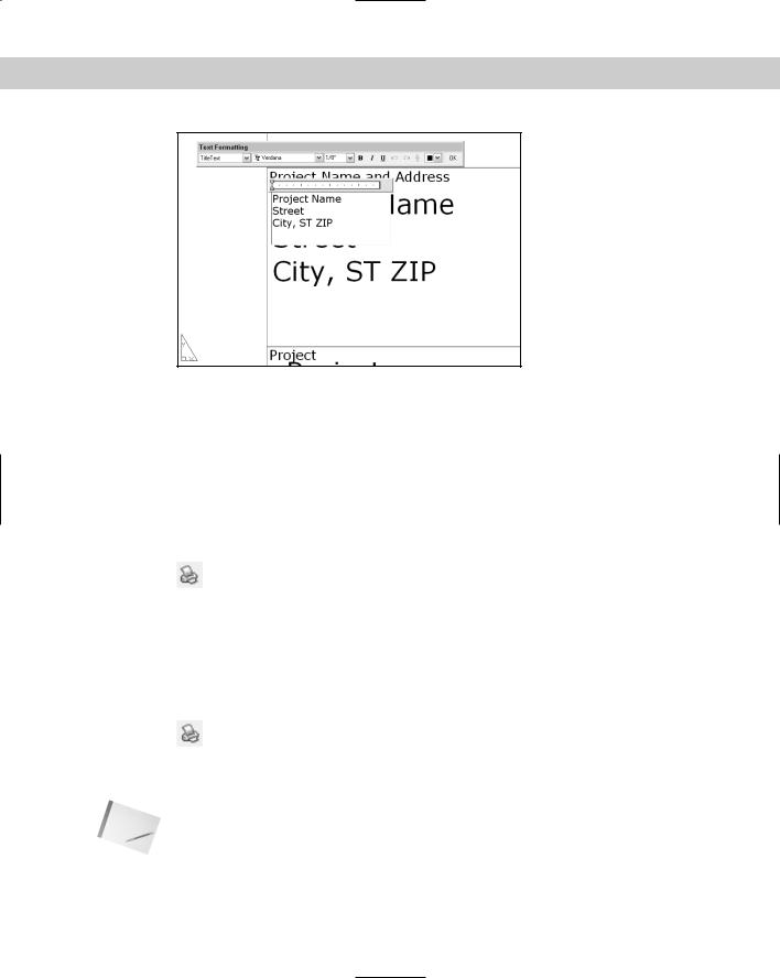
24.Double-click the Project Name text. The text editing window opens, with the Text Formatting toolbar above it, as shown in Figure 1-8.
16 |
Part I AutoCAD and AutoCAD LT Basics |
Figure 1-8: The text editing window.
25.Select the text by dragging from the upper-left corner to the lower-right corner. Type the following:
Double-hung window 2010 Coral Lane Fairfield, IA 12345
Click OK on the Text Formatting toolbar to close the text editing window.
26. To return to your previous view, choose Zoom Previous on the Standard toolbar.
27.You’re ready to print your drawing! Because readers will have varying setups, you can print directly to your printer. However, if you have a plotter set up, you can
use that. (The layout is set up to fit on an 81⁄2-x-11-inch or A-size paper.) Choose Plot on the Standard toolbar. The Plot dialog box opens. (I cover printing and plotting in Chapter 17. Appendix A explains how to configure a printer or plotter.)
28.In the Printer/plotter section of the Plot dialog box, choose the printer or plotter that you want to use from the Name drop-down list.
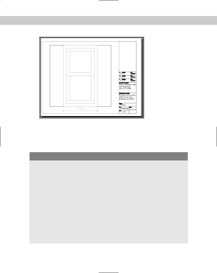
29.Click the Preview button to open the preview window. You should see the window and its title block laid out as shown in Figure 1-9.
30.Make sure your printer or plotter has an 81⁄2-x-11-inch or A-size sheet of paper, and click the Plot button on the Preview window’s toolbar. Congratulations!
You’ve just created and printed your first drawings!
Leave the drawing open on your screen. You practice closing a drawing later in this chapter.
Note If things don’t seem right, click the Close Preview Window button and review the previous steps to see if you can find the problem. Also see the sidebar, “Help! My drawing doesn’t look like the figure.”
Chapter 1 Starting to Draw |
17 |
Figure 1-9: Viewing the window in Preview mode.
In this exercise, you practiced many of the skills that you need to use AutoCAD or AutoCAD LT effectively. Most of your work in AutoCAD or AutoCAD LT builds on these basic skills. The rest of the chapters in this book explain these procedures in much more detail as well as many more features not covered in this beginning exercise.
Help! My drawing doesn’t look like the figure
If your drawing doesn’t look like the image shown in Figure 1-6, there could be several reasons. To fix the problem, try one of the following solutions:
You may have made a mistake. If you think that’s the case, start over and follow the prompts again.
You may have started AutoCAD or AutoCAD LT based on a template with different properties than the default. Be sure to use the template on the AutoCAD 2005 and AutoCAD LT 2005 Bible CD-ROM as explained in Step 2 of the previous exercise. Then follow the prompts again.
If your drawing still seems wrong, put the CD-ROM that accompanies this book in your CD-ROM drive. Choose File Open and use the Open dialog box to find ab01-01.dwg on the CD-ROM. This drawing contains the end result of the exercise. You can try to find the difference between this drawing and yours. You can also copy ab01-01.dwg from the CD-ROM to your hard drive and print or plot it.
One of the preceding options should solve your problem. If you began more than one new drawing, you probably have more than one drawing currently open. You can switch from one open drawing to another by choosing any open drawing from the Window menu.