

- •Foreword
- •Preface
- •Is This Book for You?
- •How This Book Is Organized
- •How to Use This Book
- •Doing the Exercises
- •Conventions Used in This Book
- •What the Icons Mean
- •About the CD-ROM
- •Other Information
- •Contacting the Author
- •Acknowledgments
- •Contents at a Glance
- •Contents
- •Getting Acquainted with AutoCAD and AutoCAD LT
- •Starting AutoCAD and AutoCAD LT
- •Creating a New Drawing
- •Using the AutoCAD and AutoCAD LT Interface
- •Creating Your First Drawing
- •Saving a Drawing
- •Summary
- •Creating a New Drawing from a Template
- •Working with Templates
- •Opening a Drawing with Default Settings
- •Opening an Existing Drawing
- •Using an Existing Drawing as a Prototype
- •Saving a Drawing Under a New Name
- •Summary
- •The Command Line
- •Command Techniques
- •Of Mice and Pucks
- •Getting Help
- •Summary
- •Typing Coordinates
- •Displaying Coordinates
- •Picking Coordinates on the Screen
- •Locating Points
- •Summary
- •Unit Types
- •Drawing Limits
- •Understanding Scales
- •Inserting a Title Block
- •Common Setup Options
- •The MVSETUP Command
- •Summary
- •Using the LINE Command
- •Drawing Rectangles
- •Drawing Polygons
- •Creating Construction Lines
- •Creating Rays
- •Summary
- •Drawing Circles
- •Drawing Arcs
- •Creating Ellipses and Elliptical Arcs
- •Making Donuts
- •Placing Points
- •Summary
- •Panning
- •The ZOOM Command
- •Aerial View
- •Named Views
- •Tiled Viewports
- •Snap Rotation
- •User Coordinate Systems
- •Isometric Drawing
- •Summary
- •Editing a Drawing
- •Selecting Objects
- •Summary
- •Copying and Moving Objects
- •Using Construction Commands
- •Creating a Revision Cloud
- •Hiding Objects with a Wipeout
- •Double-Clicking to Edit Objects
- •Grips
- •Editing with the Properties Palette
- •Selection Filters
- •Groups
- •Summary
- •Working with Layers
- •Changing Object Color, Linetype, and Lineweight
- •Working with Linetype Scales
- •Importing Layers and Linetypes from Other Drawings
- •Matching Properties
- •Summary
- •Drawing-Level Information
- •Object-Level Information
- •Measurement Commands
- •AutoCAD’s Calculator
- •Summary
- •Creating Single-Line Text
- •Understanding Text Styles
- •Creating Multiline Text
- •Creating Tables
- •Inserting Fields
- •Managing Text
- •Finding Text in Your Drawing
- •Checking Your Spelling
- •Summary
- •Working with Dimensions
- •Drawing Linear Dimensions
- •Drawing Aligned Dimensions
- •Creating Baseline and Continued Dimensions
- •Dimensioning Arcs and Circles
- •Dimensioning Angles
- •Creating Ordinate Dimensions
- •Drawing Leaders
- •Using Quick Dimension
- •Editing Dimensions
- •Summary
- •Understanding Dimension Styles
- •Defining a New Dimension Style
- •Changing Dimension Styles
- •Creating Geometric Tolerances
- •Summary
- •Creating and Editing Polylines
- •Drawing and Editing Splines
- •Creating Regions
- •Creating Boundaries
- •Creating Hatches
- •Creating and Editing Multilines
- •Creating Dlines
- •Using the SKETCH Command
- •Digitizing Drawings with the TABLET Command
- •Summary
- •Preparing a Drawing for Plotting or Printing
- •Creating a Layout in Paper Space
- •Working with Plot Styles
- •Plotting a Drawing
- •Summary
- •Combining Objects into Blocks
- •Inserting Blocks and Files into Drawings
- •Managing Blocks
- •Using Windows Features
- •Working with Attributes
- •Summary
- •Understanding External References
- •Editing an Xref within Your Drawing
- •Controlling Xref Display
- •Managing Xrefs
- •Summary
- •Preparing for Database Connectivity
- •Connecting to Your Database
- •Linking Data to Drawing Objects
- •Creating Labels
- •Querying with the Query Editor
- •Working with Query Files
- •Summary
- •Working with 3D Coordinates
- •Using Elevation and Thickness
- •Working with the User Coordinate System
- •Summary
- •Working with the Standard Viewpoints
- •Using DDVPOINT
- •Working with the Tripod and Compass
- •Getting a Quick Plan View
- •Shading Your Drawing
- •Using 3D Orbit
- •Using Tiled Viewports
- •Defining a Perspective View
- •Laying Out 3D Drawings
- •Summary
- •Drawing Surfaces with 3DFACE
- •Drawing Surfaces with PFACE
- •Creating Polygon Meshes with 3DMESH
- •Drawing Standard 3D Shapes
- •Drawing a Revolved Surface
- •Drawing an Extruded Surface
- •Drawing Ruled Surfaces
- •Drawing Edge Surfaces
- •Summary
- •Drawing Standard Shapes
- •Creating Extruded Solids
- •Drawing Revolved Solids
- •Creating Complex Solids
- •Sectioning and Slicing Solids
- •Using Editing Commands in 3D
- •Editing Solids
- •Listing Solid Properties
- •Summary
- •Understanding Rendering
- •Creating Lights
- •Creating Scenes
- •Working with Materials
- •Using Backgrounds
- •Doing the Final Render
- •Summary
- •Accessing Drawing Components with the DesignCenter
- •Accessing Drawing Content with Tool Palettes
- •Setting Standards for Drawings
- •Organizing Your Drawings
- •Working with Sheet Sets
- •Maintaining Security
- •Keeping Track of Referenced Files
- •Handling Errors and Crashes
- •Managing Drawings from Prior Releases
- •Summary
- •Importing and Exporting Other File Formats
- •Working with Raster Images
- •Pasting, Linking, and Embedding Objects
- •Summary
- •Sending Drawings
- •Opening Drawings from the Web
- •Creating Object Hyperlinks
- •Publishing Drawings
- •Summary
- •Working with Customizable Files
- •Creating Keyboard Shortcuts for Commands
- •Customizing Toolbars
- •Customizing Tool Palettes
- •Summary
- •Creating Macros with Script Files
- •Creating Slide Shows
- •Creating Slide Libraries
- •Summary
- •Creating Linetypes
- •Creating Hatch Patterns
- •Summary
- •Creating Shapes
- •Creating Fonts
- •Summary
- •Working with Menu Files
- •Customizing a Menu
- •Summary
- •Introducing Visual LISP
- •Getting Help in Visual LISP
- •Working with AutoLISP Expressions
- •Using AutoLISP on the Command Line
- •Creating AutoLISP Files
- •Summary
- •Creating Variables
- •Working with AutoCAD Commands
- •Working with Lists
- •Setting Conditions
- •Managing Drawing Objects
- •Getting Input from the User
- •Putting on the Finishing Touches
- •Summary
- •Understanding Local and Global Variables
- •Working with Visual LISP ActiveX Functions
- •Debugging Code
- •Summary
- •Starting to Work with VBA
- •Writing VBA Code
- •Getting User Input
- •Creating Dialog Boxes
- •Modifying Objects
- •Debugging and Trapping Errors
- •Moving to Advanced Programming
- •A Final Word
- •Installing AutoCAD and AutoCAD LT
- •Configuring AutoCAD
- •Starting AutoCAD Your Way
- •Configuring a Plotter
- •System Requirements
- •Using the CD with Microsoft Windows
- •What’s on the CD
- •Troubleshooting
- •Index
870 Part V Organizing and Managing Drawings
1
3
2
4
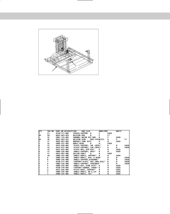
Figure 28-7: The base assembly frame.
Thanks to Robert Mack of the Dexter Company, Fairfield, Iowa, for this drawing.
The Express Tools contain three commands to help you find and change URLs that you create with hyperlinks. SHOWURLS (choose Express Web Tools Show URLs) lists all the hyperlinks in your drawing, can show you to which objects they are linked, and enables you to edit them. CHURLS (choose Express Web Tools Change URLs) prompts you to select a hyperlinked object so that you can change the hyperlink. REPURLS (choose Express Web Tools Find and Replace URLs) replaces the existing hyperlink URL of a selected hyperlinked object.
Publishing Drawings
You can save drawings as DWF (Design Web Format) files. You can use DWF files as a way to deliver files to clients and colleagues. If you place a DWF drawing on a Web site, others can view the drawing in their browser. They can zoom, pan, and print the drawing. You can place links in your drawing so that viewers can jump to supporting data, to other DWF drawings, or to other Web sites.
Understanding DWF files
DWF files are an image format for drawings. Originally meant for displaying drawings on the Web, they’re now used for any situation where you don’t want to send the actual DWG file. The DWF format allows for multiple pages. You can include as many drawings as you want, plus as many layouts as you’ve created for each drawing.
The DWF format has several advantages:
It is a vector format. Viewers can zoom in closely and see the details clearly.
DWF files are 2D representations, similar to a plot. The actual objects are not available to the viewer. They cannot edit the drawing or access object information such as layers, object coordinates, and so on. This feature maintains security for the creator of the drawing.
Chapter 28 Getting on the Internet 871
DWF files are compressed while being transmitted. Their small size reduces the time it takes to download and view them.
The Autodesk DWF Viewer enables people without AutoCAD or AutoCAD LT to view your drawings. You can also post DWF drawings on a Web site.
Viewers can zoom to named views. If you choose, they can also turn layers on and off.
DWF files support URL links to other drawings, data, or files. You can provide the viewer with supporting schedules, and so on.
Creating DWF files
To create a DWF file for a set of drawings, you use the PUBLISH command to do the following:
Create the drawing set, that is, the list of drawings and layouts to include in the DWF file
Specify a Page Setup for each drawing
Save the list of drawings or load an existing list
The PUBLISH command creates the multipage DWF format. The PUBLISHTOWEB command, which creates DWF files (but can also create JPEG or PNG files) is different — it uses a wizard and a template to format a Web page containing images of your drawings. The PUBLISHTOWEB command is covered later in this chapter. Before using the PUBLISH command, save your drawing.
Starting the PUBLISH command
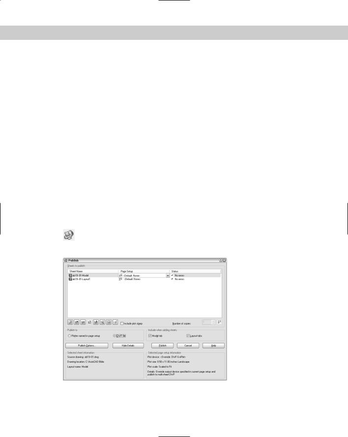
Start the PUBLISH command by choosing Publish on the Standard toolbar. The Publish dialog box opens, as shown in Figure 28-8. You see all the model and layout tabs of the
current drawing displayed.
Figure 28-8: The PUBLISH command opens the Publish Drawing Sheets dialog box, listing the model and layout tabs of the current drawing.

872 Part V Organizing and Managing Drawings
Adding drawings to the drawing list
The next step is to add any other drawings and layouts that you want to include in the drawing list. The PUBLISH command streamlines the process of defining scale and plot area for each drawing by using the page-setup information defined with the layouts. Because layouts include this information, you can quickly create drawings sets for many drawings without individually deciding how to plot each drawing. You can specify a saved page setup for individual drawings for more control. (For more information on page setups and layouts, see Chapter 18.)
You can add new drawings and layouts to the drawing list using any of the following methods:
Drag drawings directly from Windows Explorer. You can add large numbers of drawings this way — in any folder, click the first drawing, press Shift and click the last drawing.
 Click Add Sheets and choose drawings from the Select Drawings dialog box.
Click Load List and choose a saved drawing list.
You can save any drawing list and use it again later. To save a drawing list, click Save List. The Save List As dialog box opens. Change the name if you want, choose a location,
and click Save. Drawing lists have a .dsd extension. (DSD stands for Drawing Set Description.)
Note |
You can use the +PUBLISH command, a variant of the PUBLISH command that lets you start |
|
with a saved DSD file instead of with the current drawing. The Select List of Sheets dialog box |
|
opens. Choose a DSD file and click Select. You can use the –PUBLISH command with a saved |
|
DSD file to publish DWF files from a script file. In the script file, set the FILEDIA system vari- |
|
able to 0 to suppress the display of the Select List of Sheets dialog box. You’re then |
|
prompted for the DSD file. The process automatically generates a log file (with the name of |
|
the drawing list and an extension of .csv) that you can look at in case there are errors. |
Removing model space from the drawing list
By default, the model tab and layouts tabs for each drawing are all included in the drawing list. If you don’t want to see the model tab for drawings, uncheck the Model Tab check box in the Publish dialog box. After you change this setting, new drawings that you add to the drawing set will not include the model space tab.
Editing the drawing list
After you have the drawings and layouts you want, you can modify the list in several ways:
Change the sheet name: The sheet names are generated automatically from the drawing and layout names, but you might want to use a different name. Click the drawing’s row and then click the sheet name one time. Enter a new name.
Tip |
If you aren’t in the habit of renaming your layout tabs, you might find that your sheet names |
|
are rather unhelpful. Handwheel-Layout1 doesn’t explain very much. To rename a layout |
|
tab, right-click it and choose Rename. In the Rename Layout dialog box, enter a new name |
|
and click OK. |
Page setup: If you’ve specified a page setup, you can assign it to any drawing. (You can apply model page setups to model listings and layout page setups to layout listings.) Click the drawing’s page setup and then click the down arrow that appears. From the drop-down list, you can choose a page setup from the drawing or import a page setup.

Chapter 28 Getting on the Internet 873
Change drawing order: The drawing order defines how the drawings in the DWF file will be listed in the viewer. Choose a drawing and use the Move Sheet Up and Move Sheet Down buttons.
Remove drawings: To remove one or more items from the list, select them and click Remove Sheets.
Defining the output
Your list is done. Now you decide on the output. From the Publish To section of the Publish Drawing Sheets dialog box, you can choose two types of output:
DWF File: When you want to create a DWF file for viewing, choose this option. By default, the name of the file is the same as the name of the drawing (and in the same location), but with a .dwf extension. To password-protect the DWF file, enter a password. Don’t forget this password!
Plotters Named in Page Setups: Choose this option to plot all the layouts in the list. This is essentially a batch plot. Each item in the drawing set is plotted to the plotter named in its page setup, including the default page setup. The folder setting is used if you’ve saved a plotter configuration file that plots drawings to a file.
The AutoCAD LT Publish Drawing Sheets dialog box does not contain the option to publish to a plotter. You can only create DWF files with the PUBLISH command in AutoCAD LT.
Setting publish options
Click the Publish Options button to open the Publish Options dialog box, where you can specify how the DWF file will be published. You can do the following:
Specify the location of the DWF file.
Choose the type of DWF file — single-sheet or multi-sheet. You would use a single-sheet format for people using an older viewer that doesn’t support the multi-sheet format.
Specify the DWF filename now or ask to be prompted when you click the Publish button.
Create a password.
Include layer information. If you include layer information, the viewer can turn layers on or off.
Publishing
When you’ve created your drawing list and defined your output, you’re ready to publish. Click the Publish button. You get a message asking if you want to save the list of sheets. Choose Yes or No. When the publishing process is completed, you see the Plot and Publish Complete notification bubble at the lower-right corner of your screen. (I explain this bubble in Chapter 17.)
You can customize several settings for DWF files, such as the resolution and background color (for example black or white). You can also create your own ePlot plotting configuration file. For more information, see the “Customizing DWF settings” sidebar.

874 Part V Organizing and Managing Drawings
Creating DWF files from other applications
You can create a DWF file from a Microsoft Word document, an Excel spreadsheet, or any other Windows application using the new DWF Writer. You can download the DWF Writer for free from http://usa.autodesk.com/adsk/servlet/index?siteID=123112&id=3429570. The DWF Writer works as a printer driver. For example, in Microsoft Word, choose File Print and choose Autodesk DWF Writer from the Printer Name drop-down list. Then click OK to create a DWF file from your current document. You can view this document in the DWF Viewer, as I explain in the section “Viewing DWF drawings” later in this chapter.
On the |
The drawing used in the following Step-by-Step exercise on creating a DWF File, ab28-01. |
CD-ROM |
dwg, is in the Results folder on the CD-ROM. If you did the previous exercise, you also have |
|
this file in your AutoCAD Bible folder. |
STEP-BY-STEP: Creating a DWF File
1.If you did the previous exercise, use ab28-01.dwg. If not, open it from the Results folder on the CD-ROM and save it to your AutoCAD Bible folder.
2.Choose Publish from the Standard toolbar.
3.Choose ab28-01-Model and click Remove Sheets.
4.Click Publish to create the DWF file.
5.A Save Sheet List dialog box opens and asks if you want to save the current list of sheets. Click No. If you’re continuing on to the next Step-by-Step exercise, keep this drawing open.
Using the Publish to Web wizard
The Publish to Web feature creates HTML pages that display your drawings in DWF, JPEG, or PNG format. Through the use of templates, you can upload drawings without getting involved in Web-design issues.
To publish drawings to the Web, first prepare your drawings and decide how many you want to publish. Then follow these steps:
1.Choose File Publish to Web to open the Begin page of the Publish to Web Wizard.
2.Choose to create a new Web page or edit an existing one. Then click Next.
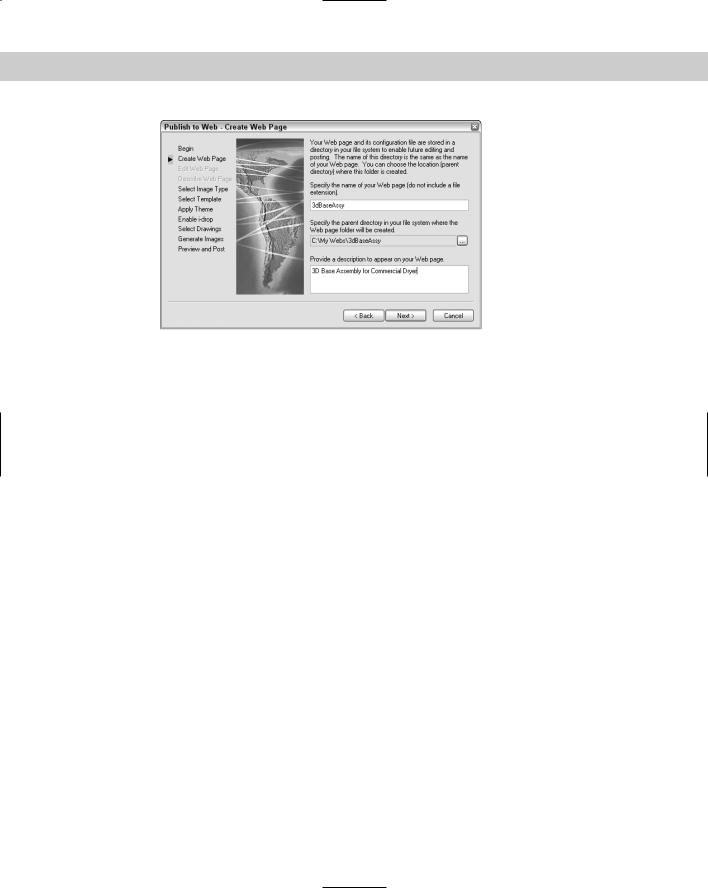
3.On the Create Web Page screen, shown in Figure 28-9, type a filename for the Web page. (This action creates a folder with this name and places all the files for the Web page in the folder.) Then click the ellipsis button (...) to navigate to where you want to create this file. If you already store Web page files on your system, you can use the same location. Finally, add a description that will appear on the Web page. Click Next.
4.On the Select Image Type screen, choose the type of image you want to create — DWF, JPEG, or PNG. As you choose each type from the drop-down list, a description appears on the screen. For JPEG and PNG, also click the image size that will appear on the Web page. Click Next.
Chapter 28 Getting on the Internet 875
Figure 28-9: On the Create Web Page screen, specify where you want to create your Web page on your own computer system and create a description of the page.
5.On the Select Template screen, choose a template that structures your Web page and click Next. You have four choices:
•Array of Thumbnails: Creates a set of thumbnail images. Clicking any image displays a larger image.
•Array plus Summary: Creates a set of thumbnail images. Adds information from the Summary tab of the Drawing Properties dialog box, displayed when the mouse cursor is over a thumbnail. (Choose File Drawing Properties to create summary information.)
•List of Drawings: Creates a list of drawings and a frame displaying a drawing image. Users select a drawing from the list to update the image in the frame.
•List plus Summary: Creates a list of drawings, an image frame, and summary information from the Summary tab of the Drawing Properties dialog box, displayed when the mouse cursor is over a thumbnail. (Choose File Drawing Properties to create summary information.)
6.On the Apply Theme screen, choose one of the preset themes that control colors and fonts on your Web page. You see an example in the preview pane. Click Next.
7.On the Enable i-drop screen, choose whether you want to create an i-drop Web page so that users can drag actual drawings from the Web page into a drawing. Click Next.
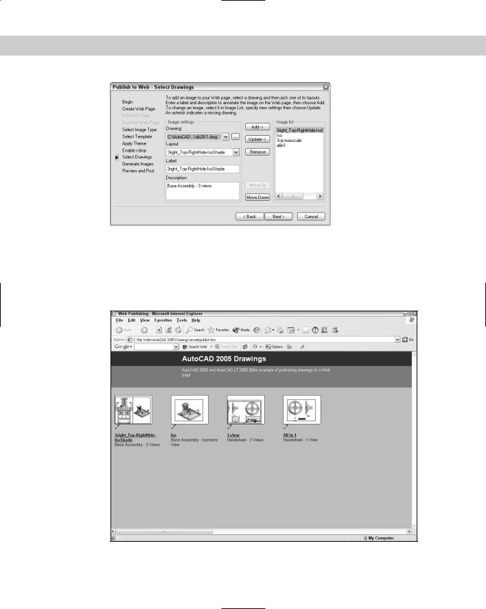
8.On the Select Drawings screen, shown in Figure 28-10, choose the drawings that you want to publish. If the drawing is open, you can select it from the Drawing drop-down list. Select each drawing, choose a layout (or model) from the Layout drop-down list, type a label, and type a description to appear on the Web page. Then click Add. (If the drawing is not open, click the ellipsis button, navigate to the drawing, and click Open. Enter a label and description and then click Add.) Click Next.
9.On the Generate Images screen, choose to regenerate either all images or only those that have changes. (There is no difference if you’re creating a new Web page.) Click Next and wait for the plotting process to complete.
876 Part V Organizing and Managing Drawings
Figure 28-10: On the Select Drawings screen, add each drawing you want to include on the Web page and specify a layout, label, and description for each.
10.On the Preview and Post screen, click Preview to preview what the Web page will look like. Your Web browser opens and displays a fully functional Web page, including links, if any. Figure 28-11 shows an example.
Figure 28-11: A preview of some drawings using the Array of Thumbnails template and DWF files. You can click on any thumbnail to see the full-size DWF file. Note the i-drop icons.
Chapter 28 Getting on the Internet 877
11.Click Post to post your new Web page. The Posting Web dialog box opens, which is like the Save As dialog box. In the Save In drop-down list, choose the desired location. To use FTP to post directly to a server, choose FTP locations or choose FTP from the Places list. (If you’re saving to an Intranet, you’ll choose a location designated by your network administrator.) Double-click the FTP location and wait until you see the folder structure of your Web site. If you want, double-click one of the folders to save there. Click Save. You should see a File Upload dialog box showing the progress of the file transfer. If everything goes well, you’ll see the success message shown in Figure 28-12.
Figure 28-12: Success with the file transfer!
12.If you want, click Send Email to notify people of the URL to the new Web page.
13.To find your new page, look for a file named acwebpublish.htm.
You can always upload the files by yourself, using your own FTP program or whatever other means you use to post to the Web site.
Customizing DWF settings
You can modify the PC3 file that defines the DWF file to specify certain settings that you might want, including compression, resolution, and whether to include layer information. The new DWF file format follows the specification of the DWF6 ePlot.pc3 file. For safety, it’s good to make a backup of the PC3 file before modifying it. To find the PC3 file, choose File Plotter Manager. Double-click DWF6 ePlot.pc3. Right-click the file and choose Copy. Right-click in the file listing and choose Paste. Rename the copy (perhaps DWF6 ePlot-original.pc3). If you don’t like the results of your editing, delete the DWF6 ePlot.pc3 file and remove -original from the name of the copy.
To modify the PC3 file, follow these steps:
1.Choose File Plotter Manager.
2.Double-click DWF6 ePlot.pc3.
3.Click the Device and Document Settings tab and choose Custom Properties. In the middle of the dialog box, click the Custom Properties button to open the DWF6 ePlot Properties dialog box.
Continued

878 Part V Organizing and Managing Drawings
Continued
You can specify the following settings:
Resolution (dpi): Defines the resolution for vector and raster (bitmap) graphics. Of course, a higher resolution results in a larger file size. You can choose from the dropdown lists or enter a custom resolution. For plotting, you can use a resolution that matches the output of your plotter or printer. Use high resolutions for viewing highly detailed drawings.
Format: Specifies the compression format. Compressed Binary is the recommended format and the default. The Zipped ASCII Encoded 2D Stream (advanced) option is an ASCII (text) format that can be uncompressed using WinZip or a similar program.
Font Handling: Specifies how many fonts can be included in the file. Use this setting to reduce file size by limiting the number of possible fonts.
•Use Capture None (all viewer supplied) if you’re sure that the viewer’s computer has all the fonts that the DWF file needs to display.
•Use Capture Some to specify which fonts the DWF file includes. Then click Edit List and deselect all the fonts that you don’t need. The fonts still selected will display properly even if they aren’t on the viewer’s computer.
•Use Capture All if you want to include all fonts from the drawing in the DWF file. When you choose this option, the All as Geometry (largest file size) option becomes available. This includes fonts as geometry (objects) in your drawing and requires plotting the drawing at 1:1 or better to get good-quality output.

Chapter 28 Getting on the Internet 879
Background Color: Specifies the background color shown in the viewer. Click the Color drop-down list. If you change the background from black to white, make sure that the objects are still easily visible. (Yellow doesn’t show up very well on white.) If viewers will be plotting from Autodesk DWF Viewer, change the background color to white or their plots come out with a black background! If the background color is set to black, color 7 objects are plotted in white. For all other background colors, color 7 objects are plotted in black.
Virtual Pen Set Patterns: If, and only if, in the Plotter Configuration File dialog box, for Vector Graphics, you chose 255 Virtual Pens in the Color Depth drop-down list, you’ll see an option to edit virtual pen set patterns. You can set the color, width, and other properties of virtual pens.
Include Layer Information: Includes layer information so that viewers can turn layers on and off. This option is off by default. You can set this option in the Publish Options dialog box, as explained earlier in this section.
Show Paper Boundaries: This displays a paper boundary such as the one you see on a layout tab. It’s on by default and not editable.
Save Preview in DWF: This option is only for use on Buzzsaw.com, because a small preview is always saved with the DWF file.
When you finish specifying the DWF format, click OK. You then see a message asking if you want to apply the changes for the current plot only (which creates an override of the configuration file but doesn’t change it) or to save the changes to the file (which creates a permanent change — you can always change it back).
Editing Web pages
You can edit your Web page — for example, you can delete existing drawings and add new ones. Start the Publish to Web command and choose Edit Existing Web Page on the first screen. Click Next and choose the Web page you want to edit by choosing a PTW (Publish to Web) file. Click Next again. From this point on, you can change any existing information.
On the Select Drawings screen, click Update to update a drawing that has changed since the last time you created the Web page. Click Remove to remove a drawing. To add a new drawing, follow the same procedures described in the previous section.
To change the order of the drawings, select a drawing from the list and click Move Up or Move Down until you get the results you want. Continue through the wizard and re-post your drawings.
Viewing DWF drawings
The final step is to view the drawings. If you use the Publish to Web Wizard to create JPEG or PNG drawings, you simply view them like any other image. However, DWF drawings, whether viewed locally on a computer or from a Web site, can be panned and zoomed and offer other viewing options as well. To view a DWF drawing, you need a special program called Autodesk DWF Viewer. Autodesk DWF Viewer is free and comes with AutoCAD or AutoCAD LT. It is also available as a free download from the Autodesk Web site at www.autodesk.com/ expressviewer. Autodesk DWF Viewer replaces Volo View Express, used with earlier versions of DWF files.
880 Part V Organizing and Managing Drawings
You view the DWF files using the new drawing reader, Autodesk DWF Viewer. Autodesk DWF Viewer can function in two ways:
As a stand-alone reader, it opens like any program. (You can usually find it by choosing Start [All] Programs Autodesk Autodesk DWF Viewer.) Choose File Open to open a DWF file. You can also double-click the DWF file in Windows Explorer. Use the reader this way to view DWF files without using AutoCAD or AutoCAD LT.
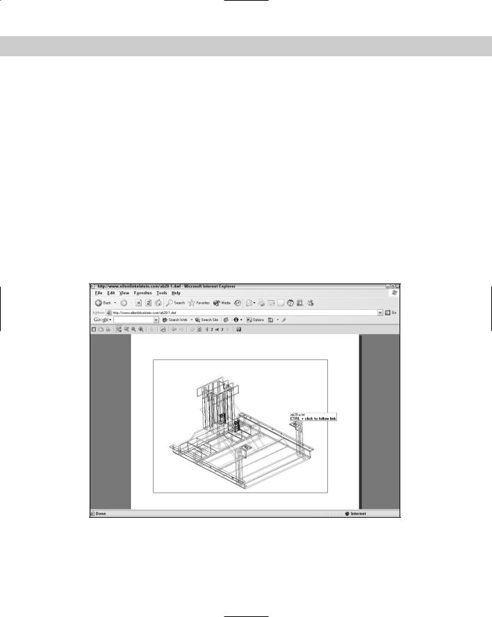
As an ActiveX component, Autodesk DWF Viewer functions within Microsoft Internet Explorer, as shown in Figure 28-13. Use the reader within Internet Explorer when you’ve posted DWF files on a Web site. Enter the URL in the browser and the DWF file appears.
Figure 28-13: Here is Autodesk DWF Viewer used in Internet Explorer.
If you send DWF files to clients or colleagues, you can send them the Install file for Autodesk DWF Viewer as well. This file is about 3MB so including the file in an e-mail or as a download on a Web page is not difficult.
If you’ve given a DWF file a password, a dialog box opens requesting the password before the DWF file is displayed.
Using view options
To view any sheet in the DWF file, choose it from the list as the left or use the Next and Previous buttons on the viewer’s toolbar. Choose View Views to display any named views that were saved with the drawing. You can use saved views to help a customer focus on certain details and provide information about the views you saved.
Chapter 28 Getting on the Internet 881
By default, layer information is not included in the DWF format. As explained earlier in this chapter, you can include layer information if you want. If the DWF file includes layer information, viewers can choose View Layers to open the Layers window, where they can choose any layer and click the Off or On button to turn that layer off or on.
Viewers have complete freedom to pan and zoom however they want. Note that if you’re sending a DWF file to a client who doesn’t use AutoCAD or AutoCAD LT, the controls may not be obvious. The controls are as follows:
Fit to Window is equivalent to a Zoom Extents. The button looks like the Zoom Extents button.
Zoom Rectangle does a Zoom Window.
Zoom enables you to zoom. Drag up to zoom in and drag down to zoom out.
Pan enables you to pan. Drag in any direction to pan in that direction.
A mouse with an IntelliMouse wheel works just like in AutoCAD or AutoCAD LT. Zoom in by scrolling forward and zoom out by scrolling backward. Press the wheel and drag to pan.
If the DWF file has hyperlinks, when your cursor passes over a URL area, a tooltip appears telling you to Ctrl+click to follow the link , as shown in Figure 28-14.
Figure 28-14: Passing over a URL in a DWF file.

882 Part V Organizing and Managing Drawings
Printing and plotting
You can print/plot drawings from Autodesk DWF Viewer. The print options are somewhat like those in Microsoft Word because they take into account the fact that the DWF file can have many pages. Click the Print button to open the Print dialog box, as shown in Figure 28-15.
Figure 28-15: The Print dialog box helps you print or plot drawings from Autodesk DWF Viewer.
The Print dialog box offers the following features:
Printer: In the Printer section, choose the printer or plotter you want to use. Click Properties to specify how the printer/plotter functions. The features depend on the device you choose.
Print What: In the Print What section, you can choose to print the full page or the current view. Check Force All Geometry to Black to print in black only. This feature doesn’t affect the color of raster images.
Page Size & Orientation: Choose the page size from the drop-down list and choose Portrait or Landscape. The paper sizes that are available vary depending on your printer or plotter.
Reduce/Enlarge Drawing: Check Fit to Paper Size to scale the drawing to the chosen paper size. To scale the drawing, uncheck Fit to Paper Size and enter a scale percentage. If the drawing will be larger than the paper, you can check Show Tiles in Page View to display dashed lines that indicate how the drawing will be divided up into sheets of paper.
Print Range: You can print the current page or all the pages, or you can specify which pages you want to print.

Chapter 28 Getting on the Internet 883
Tip |
On the toolbar’s drop-down list of sheets in the drawing set, each layout is numbered. You |
|
can use these numbers to specify which pages you want to print. |
Copies: You can specify how many copies you want of each drawing, reverse their order so you don’t have to shuffle through all the pages yourself, and collate them.
There is no print preview.
Click OK to print. If you choose a size that doesn’t fit on one sheet of paper, you see a message saying that the drawing may print across several pages.
In the following exercise, I use the capability of Internet browsers to browse your hard drive as well as the Internet. This enables you to complete the exercise even if you don’t have an Internet connection available. You need only the files on this book’s CD-ROM, your Internet browser, and Autodesk DWF Viewer.
Using DWF Composer and the Markup Manager
DWF Composer is a new program that enables you to markup DWF files. The idea is to send out DWF files for review and have the reviewers mark comments and changes on the DWF (electronically, of course). In addition to marking up a DWF file, reviewers can navigate through sheet sets, measure lengths and areas, reorganize the sheets in a sheet set, and track changes, Back in AutoCAD, you use the new Markup Manager (choose Markup Manager on the Standard toolbar or press Ctrl-7) to open the marked-up DWF. You can then incorporate these changes back into the original DWG file.
You can also incorporate multiple DWF files into one multi-page DWF file using DWF Composer. If you create DWF files from word processing or spreadsheet files using DWF Writer (see “Creating DWF files from other applications” earlier in this chapter), you can include these files with your drawings in one DWF file.
You need to purchase DWF Composer separately. For more information go to http:// usa.autodesk.com/adsk/servlet/item?siteID=123112&id=4006617.
On the
CD-ROM
The files used in the following Step-by-Step exercise on viewing a DWF drawing, Results\ ab28-01.dwf, Drawings\ab28-a.txt, and Drawings\ab28-b.dwf, are on the CD-ROM. If you didn’t do the previous Step-by-Step exercise, copy all three files from the CD-ROM to your AutoCAD Bible folder.
STEP-BY-STEP: Viewing a DWF Drawing
1.Open Windows Explorer and navigate to ab28-01.dwf in your AutoCAD Bible folder. Double-click the file to open it in Autodesk DWF Viewer.
Note |
If the DWF file were on a Web site, you would view it by typing the URL in Internet Explorer. |
2.Autodesk DWF Viewer opens automatically and displays the DWF file created in the previous Step-by-Step exercise. From the List tab in the left pane of the Autodesk DWF Viewer, choose the second sheet, labeled (2)ab28-01-Iso (11x8.5 in), as shown in Figure 28-16.
884 Part V Organizing and Managing Drawings
1
2
Figure 28-16: The DWF file as seen in Autodesk
DWF Viewer.
3.Press Ctrl and click 1 in Figure 28-16. The text shown in Figure 28-17 opens in a new Internet Explorer window. (You may have to minimize Autodesk DWF Viewer to see the text.) This comes from an Excel spreadsheet saved in text format.
4.Right-click in the drawing to open the shortcut menu. Choose Zoom Rectangle. Drag a window to zoom in. Choose Pan from the menu and pan to the left. Choose Fit in Window to return to the previous view. (If you want, choose Print to print the drawing to the system printer.)
5.Press Ctrl and click 2 in Figure 28-16. You see the horizontal angle in a new Internet Explorer window.
6.Close Autodesk DWF Viewer and the Internet Explorer windows.
Figure 28-17: The text database for the drawing.