

- •Foreword
- •Preface
- •Is This Book for You?
- •How This Book Is Organized
- •How to Use This Book
- •Doing the Exercises
- •Conventions Used in This Book
- •What the Icons Mean
- •About the CD-ROM
- •Other Information
- •Contacting the Author
- •Acknowledgments
- •Contents at a Glance
- •Contents
- •Getting Acquainted with AutoCAD and AutoCAD LT
- •Starting AutoCAD and AutoCAD LT
- •Creating a New Drawing
- •Using the AutoCAD and AutoCAD LT Interface
- •Creating Your First Drawing
- •Saving a Drawing
- •Summary
- •Creating a New Drawing from a Template
- •Working with Templates
- •Opening a Drawing with Default Settings
- •Opening an Existing Drawing
- •Using an Existing Drawing as a Prototype
- •Saving a Drawing Under a New Name
- •Summary
- •The Command Line
- •Command Techniques
- •Of Mice and Pucks
- •Getting Help
- •Summary
- •Typing Coordinates
- •Displaying Coordinates
- •Picking Coordinates on the Screen
- •Locating Points
- •Summary
- •Unit Types
- •Drawing Limits
- •Understanding Scales
- •Inserting a Title Block
- •Common Setup Options
- •The MVSETUP Command
- •Summary
- •Using the LINE Command
- •Drawing Rectangles
- •Drawing Polygons
- •Creating Construction Lines
- •Creating Rays
- •Summary
- •Drawing Circles
- •Drawing Arcs
- •Creating Ellipses and Elliptical Arcs
- •Making Donuts
- •Placing Points
- •Summary
- •Panning
- •The ZOOM Command
- •Aerial View
- •Named Views
- •Tiled Viewports
- •Snap Rotation
- •User Coordinate Systems
- •Isometric Drawing
- •Summary
- •Editing a Drawing
- •Selecting Objects
- •Summary
- •Copying and Moving Objects
- •Using Construction Commands
- •Creating a Revision Cloud
- •Hiding Objects with a Wipeout
- •Double-Clicking to Edit Objects
- •Grips
- •Editing with the Properties Palette
- •Selection Filters
- •Groups
- •Summary
- •Working with Layers
- •Changing Object Color, Linetype, and Lineweight
- •Working with Linetype Scales
- •Importing Layers and Linetypes from Other Drawings
- •Matching Properties
- •Summary
- •Drawing-Level Information
- •Object-Level Information
- •Measurement Commands
- •AutoCAD’s Calculator
- •Summary
- •Creating Single-Line Text
- •Understanding Text Styles
- •Creating Multiline Text
- •Creating Tables
- •Inserting Fields
- •Managing Text
- •Finding Text in Your Drawing
- •Checking Your Spelling
- •Summary
- •Working with Dimensions
- •Drawing Linear Dimensions
- •Drawing Aligned Dimensions
- •Creating Baseline and Continued Dimensions
- •Dimensioning Arcs and Circles
- •Dimensioning Angles
- •Creating Ordinate Dimensions
- •Drawing Leaders
- •Using Quick Dimension
- •Editing Dimensions
- •Summary
- •Understanding Dimension Styles
- •Defining a New Dimension Style
- •Changing Dimension Styles
- •Creating Geometric Tolerances
- •Summary
- •Creating and Editing Polylines
- •Drawing and Editing Splines
- •Creating Regions
- •Creating Boundaries
- •Creating Hatches
- •Creating and Editing Multilines
- •Creating Dlines
- •Using the SKETCH Command
- •Digitizing Drawings with the TABLET Command
- •Summary
- •Preparing a Drawing for Plotting or Printing
- •Creating a Layout in Paper Space
- •Working with Plot Styles
- •Plotting a Drawing
- •Summary
- •Combining Objects into Blocks
- •Inserting Blocks and Files into Drawings
- •Managing Blocks
- •Using Windows Features
- •Working with Attributes
- •Summary
- •Understanding External References
- •Editing an Xref within Your Drawing
- •Controlling Xref Display
- •Managing Xrefs
- •Summary
- •Preparing for Database Connectivity
- •Connecting to Your Database
- •Linking Data to Drawing Objects
- •Creating Labels
- •Querying with the Query Editor
- •Working with Query Files
- •Summary
- •Working with 3D Coordinates
- •Using Elevation and Thickness
- •Working with the User Coordinate System
- •Summary
- •Working with the Standard Viewpoints
- •Using DDVPOINT
- •Working with the Tripod and Compass
- •Getting a Quick Plan View
- •Shading Your Drawing
- •Using 3D Orbit
- •Using Tiled Viewports
- •Defining a Perspective View
- •Laying Out 3D Drawings
- •Summary
- •Drawing Surfaces with 3DFACE
- •Drawing Surfaces with PFACE
- •Creating Polygon Meshes with 3DMESH
- •Drawing Standard 3D Shapes
- •Drawing a Revolved Surface
- •Drawing an Extruded Surface
- •Drawing Ruled Surfaces
- •Drawing Edge Surfaces
- •Summary
- •Drawing Standard Shapes
- •Creating Extruded Solids
- •Drawing Revolved Solids
- •Creating Complex Solids
- •Sectioning and Slicing Solids
- •Using Editing Commands in 3D
- •Editing Solids
- •Listing Solid Properties
- •Summary
- •Understanding Rendering
- •Creating Lights
- •Creating Scenes
- •Working with Materials
- •Using Backgrounds
- •Doing the Final Render
- •Summary
- •Accessing Drawing Components with the DesignCenter
- •Accessing Drawing Content with Tool Palettes
- •Setting Standards for Drawings
- •Organizing Your Drawings
- •Working with Sheet Sets
- •Maintaining Security
- •Keeping Track of Referenced Files
- •Handling Errors and Crashes
- •Managing Drawings from Prior Releases
- •Summary
- •Importing and Exporting Other File Formats
- •Working with Raster Images
- •Pasting, Linking, and Embedding Objects
- •Summary
- •Sending Drawings
- •Opening Drawings from the Web
- •Creating Object Hyperlinks
- •Publishing Drawings
- •Summary
- •Working with Customizable Files
- •Creating Keyboard Shortcuts for Commands
- •Customizing Toolbars
- •Customizing Tool Palettes
- •Summary
- •Creating Macros with Script Files
- •Creating Slide Shows
- •Creating Slide Libraries
- •Summary
- •Creating Linetypes
- •Creating Hatch Patterns
- •Summary
- •Creating Shapes
- •Creating Fonts
- •Summary
- •Working with Menu Files
- •Customizing a Menu
- •Summary
- •Introducing Visual LISP
- •Getting Help in Visual LISP
- •Working with AutoLISP Expressions
- •Using AutoLISP on the Command Line
- •Creating AutoLISP Files
- •Summary
- •Creating Variables
- •Working with AutoCAD Commands
- •Working with Lists
- •Setting Conditions
- •Managing Drawing Objects
- •Getting Input from the User
- •Putting on the Finishing Touches
- •Summary
- •Understanding Local and Global Variables
- •Working with Visual LISP ActiveX Functions
- •Debugging Code
- •Summary
- •Starting to Work with VBA
- •Writing VBA Code
- •Getting User Input
- •Creating Dialog Boxes
- •Modifying Objects
- •Debugging and Trapping Errors
- •Moving to Advanced Programming
- •A Final Word
- •Installing AutoCAD and AutoCAD LT
- •Configuring AutoCAD
- •Starting AutoCAD Your Way
- •Configuring a Plotter
- •System Requirements
- •Using the CD with Microsoft Windows
- •What’s on the CD
- •Troubleshooting
- •Index
950 Part VI Customizing AutoCAD
Customizing a Menu
Menu files are long and complex. However, you often don’t need to deal with every part of the menu file. And even simple changes can be very useful. Start simple and take it from there.
Menu files have eight major types of sections, each defining a different menu section:
Button menus control the buttons on your mouse or puck.
POP menus are the pull-down menus at the top of your screen. You can also create shortcut menus in this section. Shortcut menus appear when you click the right mouse button. (See Chapter 3 for more information on right-clicking.)
Toolbar menus create toolbars.
Image menus create dialog boxes with images, such as the one you see when you choose Draw Surfaces 3D Surfaces in AutoCAD.
The screen menu is AutoCAD’s original menu that used to appear at the right side of your screen. (This section does not exist in AutoCAD LT.) By default, it is not displayed, but it still exists in the menu file. In AutoCAD, you can display it by choosing Tools Options, clicking the Display tab, and checking the Display Screen Menu check box.
Tablet menus control the menu that can be overlaid on a digitizing tablet.
Helpstrings create the short descriptions of each command that appear on the status bar when you place the mouse cursor over a toolbar or a menu item.
Accelerators are keyboard shortcuts. An example is Ctrl+C for the COPYCLIP command.
The menu files contain sections for these types of menus. Each section starts with three asterisks — for example, ***TOOLBARS. Most sections also have subsections that start with two asterisks. You don’t need to customize all the types of menus. You may want to customize only the pull-down menus. If you use a digitizer, you’ll want to customize the Tablet menus.
Looking at acad.mns or aclt.mns
The best way to start customizing a menu is to look at the MNS file and use it as a guide. Each type of menu has its own unique features, but certain features apply to most, if not all, menu types.
Note |
When you create a new, complete menu file based on acad.mnu or acad.mns, don’t forget |
|
that AutoCAD uses the AutoLISP routines in acad.mnl for many commands. You should, |
|
therefore, make a copy of acad.mnl with the same name as your new menu. For example, |
|
if you created a menu called mech.mnu from acad.mnu, make a copy of acad.mnl and |
|
name the copy mech.mnl. This applies to AutoCAD only. |
Here you see the beginning of the pull-down Format menu. (AutoCAD LT is the same except that it’s missing the line that starts ID_Mlstyle.)
***POP5
**FORMAT
ID_MnFormat [F&ormat] ID_Layer [&Layer...]’_layer ID_Ddcolor [&Color...]’_color
ID_Linetype [Li&netype...]’_linetype ID_Linewt [Line&weight...]’_lweight

Chapter 33 Customizing Menus 951
|
[--] |
ID_Style |
[Text &Style...]’_style |
ID_Ddim |
[&Dimension Style...]’_dimstyle |
ID_TblStyle |
[Ta&ble Style...]^c^c_tablestyle |
ID_PlotStyle |
[$(if,$(eq,$(getvar,pstylemode),1),~,)Plot |
St&yle...]^C^C_plotstyle |
|
ID_Ddptype |
[&Point Style...]’_ddptype |
ID_Mlstyle |
[&Multiline Style...]^C^C_mlstyle |
|
[--] |
ID_Units |
[&Units...]’_units |
ID_Thickness |
[&Thickness]’_thickness |
ID_Limits |
[Dr&awing Limits]’_limits |
|
[--] |
ID_Ddrename |
[&Rename...]^C^C_rename |
Notice that each menu item has three parts:
The first part is a name tag. Each name tag must be unique. The most common use for the name tag is to link pull-down menu items and toolbar buttons to their status-bar help. You can also use the name tag to link a keyboard shortcut to a menu item. Name tags are only used in the POP (pull-down) and Toolbar sections of the menu. However, they aren’t mandatory even in these sections. They must not be more than 12 characters and cannot have spaces — or they are ignored.
The second part, in square brackets, is the label. This is what you actually see on the menu. The ellipses (...) after menu items provide a visual cue on the menu that these items open dialog boxes. The ampersand (&) places an underscore under the following letter. You can then type the letter to execute the menu item (instead of clicking the menu item with your mouse). The Buttons, Aux, and Tablet menus do not display or require any label, but you can use the label for your own notes. Shortcut menus don’t display the label either, but the label is required.
Note In Windows 2000 and XP, by default, the underscores only appear if you access the menu using the keyboard. To access a menu, press Alt and the underscores appear. Then type the underscored letter to open the menu. To choose a menu item, type its underscored letter. To disable this behavior and display the underscores all the time, choose Start Control Panel and choose Display. If you have Windows XP, choose the Appearance tab and click the Effects button. Uncheck the Hide Underlined Letters for Keyboard Navigation Until I Press the Alt Key check box. If you have Windows 2000, choose the Effects tab. Uncheck the Hide Keyboard Navigation Indicators Until I Use the Alt Key check box.
The third part is the actual command, called a menu macro. This can be a simple command, any group of commands, or an AutoLISP expression if you’re using AutoCAD. The following conventions are recommended practice:
•Add an apostrophe (‘) before commands that can be used transparently. (Otherwise, the commands won’t work transparently when chosen from the menu macro.)
•All other commands start with ^C^C, which is equivalent to pressing Esc twice. This cancels any other command that may be active. One Esc is generally enough, but occasionally two are necessary.
•The underscore is used before each command. This allows translation of the command into other languages. Your menus would automatically be translated into French in France!

952 Part VI Customizing AutoCAD
Figure 33-4 shows the Format menu. Compare it to the text of the menu file. (This is the AutoCAD menu. The AutoCAD LT menu is slightly different.)
Figure 33-4: The Format menu displays the labels shown in the menu file.
Writing menu macros
The menu macro is the heart of the menu. You need to know a number of special characters and conventions in order to write menu macros. Table 33-2 lists some of the most common ones.
|
|
Table 33-2: Special Characters for Menu Macros |
|
|
|
|
Character |
Description |
|
|
|
|
; |
Equivalent to pressing Enter. The end of a line in a menu macro is also equivalent to |
|
|
pressing Enter. Use the semicolon when you need two returns at the end of a line or |
|
|
any time you want to indicate pressing Enter. Some commands, such as DTEXT/TEXT, |
|
|
also require a return to complete. You can also use ^M. |
|
Space |
Similar to pressing Enter, except when entering text (to create a text object) that |
|
|
contains spaces (such as between words). Use between the command and its |
|
|
options. Note that you can use a space even on the command line for most |
|
|
commands. |
|
\ |
Pauses for user input, such as picking a point or typing a value. |
|
+ |
Used at the end of a line to continue the macro on the next line. |
|
* |
Placed at the beginning of a macro (before the ^C^C), repeats the macro until you |
|
|
end it by pressing Esc or choosing another menu item. For example, the POINT |
|
|
command works this way. |
|
^P |
Turns on and off (toggles) the display of the menu macro, including menu prompts, |
|
|
on the command line. |
Note |
|
|
Because the backslash pauses for user input, you cannot use it to specify a path, as in |
||
|
C:\Program Files\AutoCAD 2005\Support. Use the regular slash (/) instead. |
|

Chapter 33 Customizing Menus 953
Here is one line from the Draw pull-down menu that uses the backslash and the space:
ID_ArcStCeAn |
[S&tart, Center, Angle]^C^C_arc \_c \_a |
Here’s how this command works:
^C^C |
Cancels any previous command. |
_arc |
Starts the ARC command, enabling translation to another language version |
|
of AutoCAD or AutoCAD LT. |
Space |
Equivalent to pressing the spacebar, which acts like pressing Enter after |
|
typing arc on the command line. The command line displays the Specify |
|
start point of arc or [Center]: prompt. |
\The backslash lets you specify a start point.
_c |
Chooses the Center option, enabling translation to another language. |
Space |
Equivalent to pressing the spacebar, which acts like pressing Enter after |
|
typing c on the command line (for the Center option). The command line |
|
displays the Specify center point of arc: prompt. |
\The backslash lets you specify a center point.
_a |
Chooses the Angle option. Because this is at the end of the command, you |
|
don’t need to specify a pause. The user specifies an angle and presses |
|
Enter, ending the command and drawing the arc. |
The backslash allows for only one input, except when used with the SELECT command. Therefore, you can use the SELECT command in menu macros to collect a selection set and then use another command with the Previous option to act on the entire selection set. For example:
ID_MoveRight [Move .1 Right]^C^Cselect \move previous ;.1,0 ;
This macro cancels any existing command, starts the SELECT command, and lets you select as many objects as you want. You end object selection by pressing Enter. Then the macro automatically moves those objects to the right by 0.1 unit.
Here are a few more examples of macros from earlier chapters.
You could place this macro on a pull-down menu to make a selected polyline 0.1-unit wide:
^C^Cpedit \w .1 ;
You would use the following macro to automatically draw four circles with the specified centers and radius. It uses a plus sign near the end because the macro is too long to fit on one line.
^C^Ccircle 2,2 1.5 circle 6,2 1.5 circle 10,2 1.5 circle + 14,2 1.5
You could use this macro to clean up a drawing. It uses CHPROP to select all the objects in a drawing, and the Color option to change their color to ByLayer. Then it uses the LAYER command to freeze the layer named “no-plot” and saves the drawing.
^C^Cchprop all c bylayer -layer f no-plot qsave
Note that using the All selection option is another way to select more than one object in a menu macro.

954 Part VI Customizing AutoCAD
Swapping menus
Sometimes you want a menu item to switch to another menu item. This is called menu swapping. Here is an example of swapping in the Buttons2 menu. (These menus are explained in the next section.)
***BUTTONS2
// Shift + button $P0=SNAP $p0=*
This menu introduces some new special characters that are used in the menus. Because you cannot customize the pick button, the first button listed is the second button. In this case, pressing Shift and the second button (the right button on a two-button mouse) opens the Object Snap menu (as you probably know). The Object Snap menu, however, is elsewhere in the menu. In fact, it is contained in the POP0 pull-down menu. This menu item, therefore, switches you to the POP0 pull-down menu and displays that menu.
The special syntax is as follows:
$section=menugroup.menuname $section=menugroup.*
If the menu group is the same as that of the menu where you’re placing the macro, you can leave it out. The different sections or menu types have their own special abbreviations for menu swapping, as shown in Table 33-3.
Table 33-3: Menu-Section Abbreviations for Menu Swapping
Abbreviation |
Menu Section |
|
|
A1–A4 |
The AUX menus 1 through 4 |
B1–B4 |
The BUTTONS menus 1 through 4 |
P0–P999 |
The POP (pull-down) menus (1 through 499 are for pull-down menus; 0 and |
|
500 through 999 are for shortcut menus) |
I |
The IMAGE menu |
S |
The SCREEN menu |
T1–T4 |
The TABLET menus 1 through 4 |
|
|
Here’s another example from the Draw pull-down menu. The first line shows the Surfaces item on the Draw menu. The next three items are items on the Surfaces submenu. The last item swaps to and displays the subsection of the IMAGE section called image_3dobjects.
ID_MnSurface |
[->Sur&faces] |
ID_Solid |
[&2D Solid]^C^C_solid |
ID_3dface |
[3D &Face]^C^C_3dface |
ID_3dsurface |
[&3D Surfaces...] $I=ACAD.image_3dobjects $I=ACAD.* |
In Figure 33-12, later in this chapter, I show the image-tile portion of the menu that this 3D Surfaces menu item displays.

Chapter 33 Customizing Menus 955
In other words, when you choose Draw Surfaces 3D Surfaces, you get a dialog box displaying all the 3D surface objects you can draw.
Tip You could use this technique to create a menu that swaps to an image menu that inserts commonly used blocks. However, the tool palettes, which I cover in Chapter 26, are another way to accomplish a similar effect.
Working on menu sections
A menu is divided into several major sections or types and each section has its own rules and syntax. There may be several subsections for a major section; for example, there are a number of button menu sections. You can also add sections. For example, users can, and often do, add a pull-down menu. Table 33-4 lists the sections in the AutoCAD and AutoCAD LT standard menus.
|
Table 33-4: Standard Menu Sections |
|
|
Section |
Function |
|
|
***BUTTONS1 |
This menu defines what happens when you press a button on a digitizing |
|
puck or other input device (but not the system mouse). The first button |
|
(pick) cannot be customized, and one button is usually reserved to open |
|
shortcut menus, so you generally only customize this button menu if you |
|
have three or more buttons on your pointing device. |
***BUTTONS2 |
This menu defines what happens when you hold down Shift and press |
|
a button on a digitizing puck or other input device (but not the system |
|
mouse). |
***BUTTONS3 |
This menu defines what happens when you hold down Ctrl and press |
|
a button on a digitizing puck or other input device (but not the system |
|
mouse). (AutoCAD only) |
***BUTTONS4 |
This menu defines what happens when you hold down both Control and |
|
Shift and press a button on a digitizing puck or other input device (but not |
|
the system mouse). (AutoCAD only) |
***AUX1 |
This is an auxiliary button menu that defines what happens when you |
|
press a button on your system mouse. The first button (pick) cannot be |
|
customized, and one button is usually reserved to open shortcut menus, |
|
so that you generally only customize an Aux menu if you have three or |
|
more buttons on your system mouse. |
***AUX2 |
This is an auxiliary button menu that defines what happens when you |
|
hold down Shift and press a button on your system mouse. |
***AUX3 |
This is an auxiliary button menu that defines what happens when you |
|
hold down Ctrl and press a button on your system mouse. |
***AUX4 |
This is an auxiliary button menu that defines what happens when you |
|
hold down Ctrl and Shift and press a button on your system mouse. |
Continued

956 Part VI Customizing AutoCAD
|
Table 33-4 (continued) |
|
|
Section |
Function |
|
|
***POP0 |
This is the first pull-down menu. Although you can display it on the menu, |
|
it is meant to be used for the shortcut menu and usually displays the |
|
object snaps. |
***POP1 |
This is the second pull-down menu. It displays the File menu commands. |
***POP2 |
This is the third pull-down menu. It displays the Edit menu commands. |
***POP3 |
This is the fourth pull-down menu. It displays the View menu commands. |
***POP4 |
This is the fifth pull-down menu. It displays the Insert menu commands. |
***POP5 |
This is the sixth pull-down menu. It displays the Format menu commands. |
***POP6 |
This is the seventh pull-down menu. It displays the Tools menu |
|
commands. |
***POP7 |
This is the eighth pull-down menu. It displays the Draw menu commands. |
***POP8 |
This is the ninth pull-down menu. It displays the Dimension menu |
|
commands. |
***POP9 |
This is the tenth pull-down menu. It displays the Modify menu commands. |
***POP10 |
This is the eleventh pull-down menu. It displays the Window menu |
|
commands. |
***POP11 |
This is the twelfth pull-down menu. It displays the Help menu commands. |
***POP500 |
This is the shortcut menu that displays the Grips menu commands that |
|
appear at the cursor when there is a hot grip and you right-click. |
***POP501 |
This is the default shortcut menu that appears when you right-click in the |
|
drawing area. |
***POP502 |
This is the default shortcut menu that appears when an object is selected |
|
and you right-click in the drawing area. |
***POP503 |
This is the shortcut menu that appears when you’re in the middle of a |
|
command and you right-click in the drawing area. |
***POP504 |
This is the shortcut menu that appears when you select a dimension |
|
object and right-click in the drawing area. |
***POP505 |
This is the shortcut menu that appears when you select a floating |
|
viewport object and right-click in the drawing area. |
***POP506 |
This is the shortcut menu that appears when you select multiple xrefs and |
|
right-click in the drawing area. |
***POP507 |
This is the shortcut menu that appears when you select an MText object |
|
and right-click in the drawing area. |
***POP508 |
This is the shortcut menu that appears when you select a Text object and |
|
right-click in the drawing area. |
***POP509 |
This is the shortcut menu that appears when you select a hatch object |
|
and right-click in the drawing area. |
***POP510 |
This is the shortcut menu that appears when you select a lwpolyline and |
|
right-click in the drawing area. |

Chapter 33 Customizing Menus 957
Section |
Function |
|
|
***POP511 |
This is the shortcut menu that appears when you select a spline and right- |
|
click in the drawing area. |
***POP512 |
This is the shortcut menu that appears when you select a polyline and |
|
right-click in the drawing area. In AutoCAD LT, this shortcut menu appears |
|
when you select multiple viewports and right-click in the drawing area. |
***POP513 |
This is the shortcut menu that appears when you select a single xref and |
|
right-click in the drawing area. In AutoCAD LT, this shortcut menu appears |
|
when you select a maximized viewport and right-click in the drawing area. |
***POP514 |
This is the shortcut menu that appears when you select a block reference |
|
that has no attributes and right-click in the drawing area. In AutoCAD LT, |
|
this shortcut menu appears when you select a minimized viewport and |
|
right-click in the drawing area. |
***POP515 |
This is the shortcut menu that appears when you select a block reference |
|
that has attributes and right-click in the drawing area. This shortcut menu |
|
is not in AutoCAD LT (but you can add it.) |
***POP516 |
This is the shortcut menu that appears when you select multiple floating |
|
viewport objects and right-click in the drawing area. This shortcut menu is |
|
not in AutoCAD LT (but you can add it). |
***POP517 |
This is the shortcut menu that appears when you select a maximized |
|
viewport and right-click in the drawing area. This shortcut menu is not in |
|
AutoCAD LT (but you can add it). |
***POP518 |
This is the shortcut menu that appears when you select a minimized |
|
viewport and right-click in the drawing area. This shortcut menu is not in |
|
AutoCAD LT (but you can add it). |
***TOOLBARS |
This section defines all the toolbars. You can add as many as you like. You |
|
can define toolbars using acad.mns or your own menu, but it’s easier to |
|
do so using the Customize dialog box, as described in Chapter 29. |
***IMAGE |
This section defines image tiles that occasionally appear in dialog boxes. |
|
AutoCAD LT doesn’t contain this menu. |
***SCREEN |
This section creates the screen menu. AutoCAD LT doesn’t contain this menu. |
***TABLET1 |
The Tablet menu is divided into four parts. Each part represents a section |
|
of the menu area on your digitizing tablet. The parts are divided into small |
|
squares, each of which can contain a menu item. This first part is left |
|
blank for you to configure. Figure 33-5 shows the tablet and its four parts. |
***TABLET2 |
This is the second part of the Tablet menu. |
***TABLET3 |
This is the third part of the Tablet menu. |
***TABLET4 |
This is the fourth part of the Tablet menu. |
***HELPSTRINGS |
This section creates status-line descriptions of menu and toolbar items |
|
that appear when you highlight a menu item or place your cursor over a |
|
toolbar button. |
***ACCELERATORS |
The Accelerators section lets you create keyboard shortcuts. These include |
|
several standard Windows shortcuts, which you should not change, such |
|
as Ctrl+C, Ctrl+V, and Ctrl+X. |
|
|
958 Part VI Customizing AutoCAD
You don’t need to have all these sections in your menu. After backing up your menu files, you can delete the button sections (if you only use a system mouse), the screen menu, and the Tablet menus (if you don’t have a digitizing tablet).
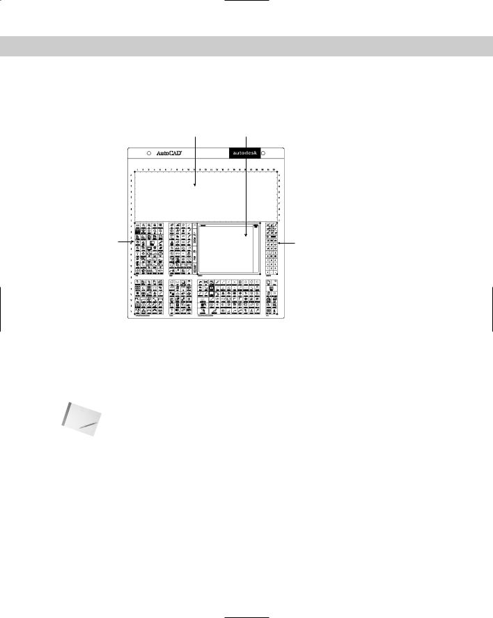
Tablet 1 |
Screen area |
Tablet 2 |
Tablet 3 |
Tablet 4 
Figure 33-5: The standard digitizer Tablet menu and its four parts, which correspond to four sections in the menu file.
The Buttons and Aux menus
The first item on the Buttons menu, BUTTONS1, is the second button because you cannot customize the pick button. You can add as many menu items as your input device has buttons. Here is the BUTTONS1 menu. The AUX1 menu is identical.
Note |
You can customize the Button and Aux sections for full menus only, not for partial menus. |
***BUTTONS1
$M=$(if,$(eq,$(substr,$(getvar,cmdnames),1,5),GRIP_),$P0=ACAD.GRIPS $P0=*);
$P0=SNAP $p0=* ^C^C
^B
^O
^G
^D
^E
^T

Chapter 33 Customizing Menus 959
Here’s what the remaining buttons do:
The second button usually functions as a return (the semicolon at the end of the line represents the return). The first part of the macro includes an expression in a programming language called DIESEL, which is beyond the scope of this book. However, its purpose is to display the Grips shortcut menu. The Grips shortcut menu only appears if you have a hot grip in your drawing.
The third button, if you have one, displays the Object Snap menu. You can change this to whatever you want.
The fourth button, ^C^C, is equivalent to pressing Esc twice.
The fifth button, ^B, is equivalent to pressing Ctrl+B, which turns Snap on and off.
The sixth button, ^O, is equivalent to pressing Ctrl+L, which turns Ortho on and off. (Once upon a time, before Windows, Ctrl+O toggled Ortho on and off.)
The seventh button, ^G, is equivalent to pressing Ctrl+G, which turns the grid on and off.
The eighth button, ^D, is equivalent to pressing Ctrl+D, which toggles the coordinate display mode.
The ninth button, ^E, is equivalent to pressing Ctrl+E, which switches to the next isometric plane.
The tenth button, ^T, is equivalent to pressing Ctrl+T, which turns the tablet on and off.
If you have a number of buttons on your pointing device, you can leave these macros as they are or change them to suit your needs.
Tip You can pan and zoom with the IntelliMouse. The MBUTTONPAN system variable controls the third button or wheel on your pointing device. By default, it’s set to 1, which supports panning and zooming. Set it to 0 to support the definition in the MNU menu file.
The following Step-by-Step exercise shows you how you can customize even a two-button device. Because you may be working on someone else’s computer, the exercise undoes the customization at the end.
STEP-BY-STEP: Customizing the Buttons Menu
1.Back up your menu files. (These are acad.mnu, acad.mns, acad.mnc, acad.mnr, and acad.mnl for AutoCAD and aclt.mnu, aclt.mns, aclt.mnc, and aclt.mnr for AutoCAD LT.)
Caution |
Don’t continue this exercise until you’ve completed Step 1. If you’re working on someone |
|
else’s computer, ask permission before doing this exercise. |
2.To make a duplicate of acad.mns or aclt.mns, right-click the file in Windows Explorer and choose Copy from the shortcut menu. Right-click again and choose Paste. Windows places a copy of the file in the same folder.
Note |
To find the location of your menu files choose Tools Options and click the Files tab. |
|
Double-click Menu, Help, and Miscellaneous File Names (or just Miscellaneous File Names in |
|
AutoCAD LT), to display the location of the menu files. |
960 Part VI Customizing AutoCAD
3.Click the copied menu file and rename it ab1.mns (that’s the number one, not the letter L). Press Enter.
4.If you have AutoCAD, do the same with acad.mnl, making a copy and renaming the copy ab1.mnl.
5.Open Notepad. (Choose Start Run. Type Notepad and click OK.) Open ab1.mns. (To find it, you need to change the Files of Type drop-down list to All Files.)
6.Look for ***MENUGROUP=ACAD or ACLT. Change the menu group name to AB1.
7.If you use a digitizing tablet or other non-system input device, scroll down to the
***BUTTONS3 and ***BUTTONS4 sections. If you use a system mouse, scroll down to the ***AUX3 and ***AUX4 sections. Change the current macros, if any, so that they read as follows:
***BUTTONS3
//Control + button
^B
***BUTTONS4
//Control + shift + button
^F
***AUX3
//Control + button
^B
***AUX4
//Control + shift + button
^F
This lets you turn Snap on and off using Ctrl plus the right button on your pointing device and lets you turn OSNAP on and off using Ctrl+Shift+right-click.
8.Save the file as a text document and close Notepad.
9.Start AutoCAD or AutoCAD LT if it isn’t already open. Open a new drawing using any template.
10.To load the menu, do one of the following:
•If you have AutoCAD, type menu . Choose ab1.mns and click Open. AutoCAD responds with the Menu loaded successfully. MENUGROUP: AB1 message on the command line.
•If you have AutoCAD LT, choose Tools Customize Menu. In the Customize dialog box, click Browse. Locate and choose ab1.mns (you may have to change the File of Type drop-down list to Menu Files (*.mnc, *.mns). Click Open. In the Customize dialog box, check the Replace All check box. Click Load, then click Close to return to your drawing.
11.Press and hold Ctrl and click the right button. The SNAP button on the status bar looks pushed in. Move your cursor around to verify that Snap is on. (If the cursor doesn’t snap to points, then PolarSnap is on. Right-click SNAP on the status bar and choose Grid Snap On.)
Note |
You may find that the shortcut menu is also displayed. This appears to be a bug. |

Chapter 33 Customizing Menus 961
12.Hold Ctrl+Shift and click the right button. OSNAP turns on if it’s currently off or turns off if it’s currently on.
13.Hold Ctrl+Shift and click the right button again to toggle OSNAP again.
14.To return to your original menu, repeat the instructions in Step 10 except choose your original acad.mns or aclt.mns.
15.Again, try using Ctrl plus the right button and Ctrl+Shift+right-click. The button no longer works as before. Instead, it opens the OSNAP shortcut menu.
Don’t save your drawing.
The POP menus
The POP menus control the pull-down and shortcut menus. The pull-down menus are the menus along the top of your screen. The shortcut menus appear at the cursor. In addition to the Snap menu, which appears when you press Shift and the right mouse button, and the Grips menu, which appears when there is a hot grip and you right-click, there are several context-sensitive shortcut menus.
Pull-down menus
The use of the ampersand (&) in the menu label is unique to the pull-down menus. As explained earlier, this places an underscore under the following letter to let you choose the menu item using the keyboard instead of the mouse. You also see [--] in several places. This adds a dividing line in a pull-down menu and is used only to organize the menu into sections.
Here is the POP2 menu:
***POP2 |
|
**EDIT |
|
ID_MnEdit |
[&Edit] |
ID_U |
[&Undo\tCtrl+Z]_u |
ID_Redo |
[&Redo\tCtrl+Y]^C^C_mredo 1 |
|
[--] |
ID_Cutclip |
[Cu&t\tCtrl+X]^C^C_cutclip |
ID_Copyclip |
[&Copy\tCtrl+C]^C^C_copyclip |
ID_Copybase |
[Copy with &Base Point\tCtrl+Shift+C]^C^C_copybase |
ID_Copylink |
[Copy &Link]^C^C_copylink |
ID_Pasteclip |
[&Paste\tCtrl+V]^C^C_pasteclip |
ID_Pastebloc |
[Paste as Bloc&k \tCtrl+Shift+V]^C^C_pasteblock |
ID_Pastehlnk |
[Paste as &Hyperlink]^C^C_pasteashyperlink |
ID_Pasteorig |
[Paste to Original Coor&dinates]^C^C_pasteorig |
ID_Pastesp |
[Paste &Special...]^C^C_pastespec |
|
[--] |
ID_Erase |
[Cle&ar\tDel]^C^C_erase |
ID_SelAll |
[Se&lect All\tCtrl+A]^C^C_ai_selall |
|
[--] |
ID_Links |
[&OLE Links...]^C^C_olelinks |
|
[--] |
ID_TextFind |
[&Find...]^C^C_find |
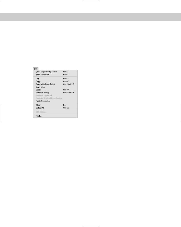
Figure 33-6 shows how the Edit menu appears.
962 Part VI Customizing AutoCAD
The POP menus can have submenus. Use the following codes to start and end submenus:
-> Starts a submenu
<- Ends a submenu
<-<- Ends a submenu of a submenu
Note that several of the items include \t and then text that describes a keyboard shortcut, such as Ctrl+A. In the label portion of a POP menu item, text after \t is moved to the right side of the menu. See Figure 33-6 for several examples of this technique.
Figure 33-6: The Edit menu. Compare it to the menu code and look for the dividing lines and the underscored letters.
Here is an example from the end of the Draw menu in AutoCAD. Notice that both the Surfaces and Solids items have submenus. At the end of the Solids submenu, the Setup item has a second-level submenu. Therefore, the Profile menu item is preceded by <-<-.
ID_MnSurface |
[->Sur&faces] |
ID_Solid |
[&2D Solid]^C^C_solid |
ID_3dface |
[3D &Face]^C^C_3dface |
ID_3dsurface |
[&3D Surfaces...]$I=ACAD.image_3dobjects $I=ACAD.* |
|
[--] |
ID_Edge |
[&Edge]^C^C_edge |
ID_3dmesh |
[3D &Mesh]^C^C_3dmesh |
|
[--] |
ID_Revsurf |
[Revolved &Surface]^C^C_revsurf |
ID_Tabsurf |
[&Tabulated Surface]^C^C_tabsurf |
ID_Rulesurf |
[&Ruled Surface]^C^C_rulesurf |
ID_Edgesurf |
[<-E&dge Surface]^C^C_edgesurf |
ID_MnSolids |
[->Sol&ids] |
ID_Box |
[&Box]^C^C_box |
ID_Sphere |
[&Sphere]^C^C_sphere |
ID_Cylinder |
[&Cylinder]^C^C_cylinder |
ID_Cone |
[C&one]^C^C_cone |
ID_Wedge |
[&Wedge]^C^C_wedge |

Chapter 33 Customizing Menus 963
ID_Torus |
[&Torus]^C^C_torus |
|
[--] |
ID_Extrude |
[E&xtrude]^C^C_extrude |
ID_Revolve |
[&Revolve]^C^C_revolve |
|
[--] |
ID_Slice |
[S&lice]^C^C_slice |
ID_Section |
[S&ection]^C^C_section |
ID_Interfere |
[&Interference]^C^C_interfere |
|
[--] |
ID_MnSetup |
[->Set&up] |
ID_Soldraw |
[&Drawing]^C^C_soldraw |
ID_Solview |
[&View]^C^C_solview |
ID_Solprof |
[<-<-&Profile]^C^C_solprof |
Figure 33-7 shows how this code looks on the AutoCAD Draw menu.
Figure 33-7: The AutoCAD Draw menu with the Solids and Setup submenus.
Tip |
The titles of pull-down POP menus appear as the menu title. Keep these fairly short to keep |
|
the menu titles from running into each other. Don’t place spaces in menu title names — it |
|
becomes hard to distinguish where one menu ends and the next one starts. |
On the |
The drawing used in the following Step-by-Step exercise on creating a pull-down partial |
CD-ROM |
menu, ab33-a.dwg, is in the Drawings folder on the CD-ROM. |

964 Part VI Customizing AutoCAD
STEP-BY-STEP: Creating a Pull-Down Partial Menu
1.If you haven’t already done so, back up the menu files. (These are the acad or aclt files ending with .mnu, .mns, .mnc, .mnr, and .mnl files. AutoCAD LT doesn’t have an
.mnl file.)
Caution |
Don’t continue with this exercise until you’ve completed Step 1. If you’re working on some- |
|
one else’s computer, ask permission before doing this exercise. |
Note |
To find the location of the menu files , choose Tools Options and click the Files tab. |
|
Double-click Menu, Help, and Miscellaneous File Names (or just Miscellaneous File Names in |
|
AutoCAD LT), to display the location of the menu files. |
2.Open Notepad. (Choose Start Run. Type notepad and click OK.)
3.To create the menu group name, the pull-down menu, and the menu name (which will appear on the menu bar), type the following:
***MENUGROUP=AB2
***POP1
[&AB2]
4.To create the first menu item with a submenu, type the following on the next few lines:
ID_SpecEdits |
[->&Special Edits] |
ID_MoveRight |
[&Move .1 Right]^C^C_select;+ |
\move;_previous;;.1,0;;
ID_Plinewdth [<-&Pedit .1]^C^C_pedit;\_w;.1;;
5. To create the next few menu items, starting with a dividing line, type the following:
[--]
ID_4circles [&4 circles]_circle;2,2 1.5;_circle;6,2;+ 1.5;_circle;10,2 1.5;_circle;14,2;1.5
ID_Cleanup [&Clean up]^C^C_chprop;_all;;_c;_bylayer;;+ -layer;_f;no-plot;;_qsave
6.End the menu file with a return. Proofread your typing and save the file as ab2.mnu in the Support folder or any other folder that you’ve placed in the support-file search path. Close Notepad.
7.Open ab33-a.dwg from the CD-ROM. Save it as ab33-01.dwg in your AutoCAD Bible folder.
8.Choose Tools Customize Menus. On the Menu Groups tab of the Menu Customization dialog box, make sure that the Replace All check box is not checked and choose Browse. Select Menu Template (*.mnu) from the Files of Type drop-down list. Find and choose ab2.mnu and click Open. Click Load. Click Yes to the message that warns you about overwriting toolbar changes (because this little menu doesn’t have any toolbars).
9.Choose the Menu Bar tab. Choose AB2 from the Menu Group drop-down list. In the Menu Bar list, choose Window so that your menu will be inserted just before the Window menu. Click Insert to insert the menu. Click Close. The menu should look like Figure 33-8. Notice the submenu and the dividing line.

Chapter 33 Customizing Menus 965
Figure 33-8: The AB2 menu, including the submenu.
10.To try out the menu, choose AB2 Special Edits Move .1 Right. At the Select objects: prompt, pick the vertical red line and right-click to end object selection. The menu macro moves the line 0.1 units to the right.
11.Choose AB2 Special Edits Pedit .1. At the Select polyline or [Multiple]: prompt, choose the green polyline. The polyline becomes 0.1-unit wide.
12.Choose AB2 Clean Up. The color of all the objects changes to ByLayer and the no-plot layer disappears.
13.Choose Tools Customize Menus and unload AB2.
14.Save your drawing.
Note |
If you made a mistake and some of the items don’t work properly, re-edit and save ab2.mnu. |
|
Then choose Tools Customize Menus, unload AB2, reload it, and insert it again. |
Replacing your partial menus (AutoCAD only)
When you’re customizing a partial menu, the process of unloading, loading, and inserting a partial menu can get pretty tedious. Here’s a routine that you can put on your partial menu. You can’t use it the first time (because the partial menu isn’t on your menu bar yet), but after that, you can use it to quickly replace your old partial menu with the new one. This routine turns off the FILEDIA system variable so that you can load and unload the partial menu on the command line, and then it unloads and loads the menu. It then uses a simple AutoLISP expression to place the menu where you want it.
ID_MenuLoad [&Reload ab2 menu]_filedia 0 + _menuunload ab2 menuload ab2.mnu (menucmd + “P10=+ab2.pop1”) _filedia 1
The first part is the name tag, which can be anything you want. The second part is the label that you see on the menu. It can also be anything you want. Then comes the menu macro. Here I’ve used the menu group name ab2 and the menu filename ab2.mnu. Replace these with your menu group name and menu filename. The AutoLISP expression syntax is
(menucmd “Pn=+menugroup.section”)
where n is the number of the POP menu to the right of where you want to insert your partial menu (P10 is usually the Help menu), menugroup is the menu group name, and section is the section name (usually POP1 if your partial menu has one pull-down menu).
If your partial menu has more than one pull-down menu, you must place each POP section using the same syntax.

966 Part VI Customizing AutoCAD
Shortcut menus
You access a shortcut menu by using the buttons on your mouse or puck. The shortcut menus are, therefore, accessed from the Buttons menu by swapping, as described earlier in this chapter.
Here you see the POP0 menu, which is the menu that appears when you press Shift and right-click.
***POP0 |
|
**SNAP |
[&Object Snap Cursor Menu] |
|
|
ID_Tracking |
[Temporary trac&k point]_tt |
ID_From |
[&From]_from |
ID_MidTwoPts |
[Mid Bet&ween 2 Points]_m2p |
ID_MnPointFi |
[->Poin&t Filters] |
ID_PointFilx |
[.X].X |
ID_PointFily |
[.Y].Y |
ID_PointFilz |
[.Z].Z |
|
[--] |
ID_PointFixy |
[.XY].XY |
ID_PointFixz |
[.XZ].XZ |
ID_PointFiyz |
[<-.YZ].YZ |
|
[--] |
ID_OsnapEndp |
[&Endpoint]_endp |
ID_OsnapMidp |
[&Midpoint]_mid |
ID_OsnapInte |
[&Intersection]_int |
ID_OsnapAppa |
[&Apparent Intersect]_appint |
ID_OsnapExte |
[E&xtension]_ext |
|
[--] |
ID_OsnapCent |
[&Center]_cen |
ID_OsnapQuad |
[&Quadrant]_qua |
ID_OsnapTang |
[Tan&gent]_tan |
|
[--] |
ID_OsnapPerp |
[&Perpendicular]_per |
ID_OsnapPara |
[Para&llel]_par |
ID_OsnapNode |
[No&de]_nod |
ID_OsnapInse |
[In&sert]_ins |
ID_OsnapNear |
[Nea&rest]_nea |
ID_OsnapNone |
[&None]_non |
|
[--] |
ID_Osnap |
[&Osnap Settings...]’_+dsettings 2 |
Note that, unlike a regular pull-down menu, the title — in this case, Snap — doesn’t appear at the top of a shortcut menu. However, a title is required anyway.
You can customize shortcut menus that are specific to a command or to a selected object. For example, if you right-click when a polyline is selected, the shortcut menu includes a Polyline Edit item. However, if you right-click when a spline is selected, the shortcut menu includes a Spline Edit item instead. Shortcut menus can also be called context menus because they’re context-sensitive. You can create your own context menus.

Chapter 33 Customizing Menus 967
|
To create a shortcut menu, you use sections ***POP500 through ***POP999. Sections |
|
***POP500 through ***POP518 in AutoCAD, and sections ***POP500 through POP514 in |
|
AutoCAD LT define the existing context-sensitive shortcut menus. |
Tip |
Although the examples shown here use both the initial underline to allow for translation and |
|
the ampersand to allow for keyboard entry, you don’t need to use these if you don’t want to. |
|
When was the last time you used the keyboard to choose a menu item on a shortcut menu? |
|
You can create two kinds of context-sensitive menus — object menus and command menus. |
|
The context-sensitive menus work only for full menus. |
Note |
If you’ve turned on time-sensitive right-clicking, remember to hold down the right mouse |
|
button long enough to open the shortcut menu. See Chapter 3 for details. |
Object menus
The Edit mode shortcut menu appears when you right-click in the drawing area while one or more objects are selected but no command is active, as shown in Figure 33-9.
You can create object menus that are specific to a type of object. You might want to add certain commands that you use often with that type of object. The commands that you add to an object menu are appended to the Edit mode shortcut menu so that the result is a menu that contains the Edit mode shortcut menu plus any additional commands that you’ve added for that type of object.
Figure 33-9: The Edit mode shortcut menu.
To create an object menu, you must name the menu either OBJECT_objectname (used when one object of a type is selected) or OBJECTS_objectname (used when more than one object of a type is selected). The object name is the DXF name of the object. (Three exceptions exist — use BLOCKREF for a block insertion with no attributes, ATTBLOCKREF for a block insertion with attributes, and XREF for an xref.)
968 Part VI Customizing AutoCAD
Cross-
Reference
To find out the object name of an object, type the following on the command line:
(cdr (assoc 0 (entget (car (entsel)))))
That’s five closing parentheses at the end. AutoCAD then prompts you to select an object. As soon as you do, you see the object’s name on the command line.
See Chapters 34 and 35, which cover AutoLISP and Visual LISP, for an explanation of the parts of this AutoLISP expression. These two chapters explain all the functions used in this expression. AutoLISP is not available for AutoCAD LT.
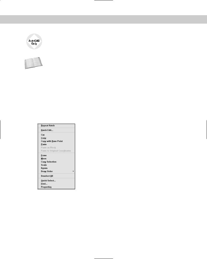
For example, to create an object menu that appears when one or more circles are selected, create an object menu named OBJECTS_circle. Look at the menu file or aclt.mns for examples to help you create your own menus. Here you see ***POP509, which is the hatch object menu:
***POP509
**OBJECT_HATCH
[Context menu for HATCH object] ID_Hatchedit [&Hatch Edit...]^C^C_hatchedit
Figure 33-10 shows how this menu appears when you select a hatch object. As you can see, the menu adds only one item, which executes the HATCHEDIT command.
Figure 33-10: The hatch object shortcut menu.
Command menus
The Command mode shortcut menu appears when you right-click in the drawing area while a command is active. You can create command menus that are specific to a command. The contents of the menu are appended to the Command mode shortcut menu (POP503) so that the result is a menu that contains the Command mode shortcut menu plus any additional commands that you’ve added for that command. The menu doesn’t include any command
menus (except for the default POP503). To create a command menu, you must name the menu COMMAND_commandname, where commandname is any valid command, including any custom
or third-party commands. After you name the menu, you can add commands to it that you would like to have available in the middle of the command just by right-clicking. Here are a couple of possibilities:

Chapter 33 Customizing Menus 969
For the LINE command, you might want to add the PLINE command to the shortcut menu, so that you can change your mind mid-command and create a polyline instead of a line. Of course, you can execute the PLINE command with one pick from the Draw toolbar, but the shortcut menu is closer.
For the ROTATE command, you might want to add the ALIGN command, in case you realize that you need to align an object instead of just rotating it.
Figure 33-11 shows a possible command menu, which turns the running OSNAP off and sets OSNAP to endpoint, using the OSMODE system variable.
Figure 33-11: A custom command menu that appears when you right-click during the ROTATE command.
Here’s the code for the menu file:
***POP519
**COMMAND_ROTATE
[Context menu for ROTATE command] ID_Align [<-A&lign]^C^C_align
Note that you cannot create a similar menu for the MOVE or COPY commands because they don’t have any options. Therefore, you can’t right-click to open a shortcut menu.
STEP-BY-STEP: Creating a Context-Sensitive Object Menu
1.If you did the exercise on customizing the Buttons menu, start Notepad by choosing Start Run, typing notepad, and clicking OK. Open ab1.mns from the Support folder. Choose File Save As and save it as ab3.mns. If you have AutoCAD, use Windows Explorer to find ab1.mnl in AutoCAD’s Support folder. Click it and rename it ab3.mnl. Then go to Step 3.
Caution |
Don’t continue with this exercise without first completing Step 1. If you’re working on some- |
|
one else’s computer, ask permission before doing this exercise. |
2.If you didn’t do the exercise on customizing the Buttons menu, back up your menu files. Then right-click acad.mns or aclt.mns in Windows Explorer and choose Copy
from the shortcut menu. Right-click again and choose Paste. Windows places a copy of acad.mns in the same folder. Click the copied menu file and type ab3.mns . If you have AutoCAD, find acad.mnl and rename it ab3.mnl.
3.Start Notepad (choose Start Run, type notepad, and click OK). Open ab3.mns. You can also double-click ab3.mnl and open it with Notepad.
Note |
To find the location of your menu files, choose Tools Options and click the Files tab. |
|
Double-click Menu, Help, and Miscellaneous File Names (or just Miscellaneous File Names in |
|
AutoCAD LT), to display the location of the menu files. |
970 Part VI Customizing AutoCAD
4.Look for ***MENUGROUP=. Change the word after the equal sign to AB3.
5.Press PageDown until you see ***POP518 (in AutoCAD) or POP514 (in AutoCAD LT), which is the last POP menu in the file. Place the cursor after the end of the last POP menu but before the ***TOOLBARS section and press Enter a couple of times. Place your cursor so that there is a blank line after the previous menu and before the next section. Type the following:
***POP519
**OBJECT_ACAD_TABLE
[Context menu for TABLE object] ID_Explode [E&xplode]^C^C_explode
6.Choose File Save. Save ab3.mns as a Text Document and close Notepad.
7.Start AutoCAD or AutoCAD LT if it isn’t already running. Open a new drawing using any template.
8.Choose Table from the Draw toolbar and click OK in the Table dialog box to create the default table. Pick an insertion point to place the table and click outside the Multiline Text Editor. Click the edge of the table to select it so you can see that the table is one object. Deselect the table.
9.Choose Tools Customize Menus. Click Browse and choose ab3.mns. (If necessary, change the Files of Type drop-down list to Menu Files (*.mnc, *.mns.) Click Open. Check the Replace All check box and click Load. Then click Close to close the dialog box. You see the message Menu loaded successfully. MENUGROUP: AB3 on the command line. (If it scrolls up, you may need to press F2 to open the Text Window.)
10.Select the table. Right-click and choose Explode from the shortcut menu. Click anywhere on the table to see that the table is now just a collection of lines.
11.To return to your original menu, choose Tools Customize Menus. Click Unload. Click Browse and choose acad.mnc or aclt.mnc. Click Open. Click Load to load the menu, and then click Close to close the dialog box.
12.Draw a new table and right-click. You no longer have the Explode option. Press Esc. Do not save your drawing.
Customizing the toolbars from the menu file
Although it’s much easier to customize toolbars directly, as explained in Chapter 29, you can also customize them from the menu file. The toolbar menu starts with ***TOOLBARS. Here is a section of the Standard toolbar code from acad.mnu:
**TB_STANDARD |
|
ID_TbStandar |
[_Toolbar(“Standard Toolbar”, _Top, _Show, 0, 0, |
1)] |
|
ID_QNew |
[_Button(“QNew”, “RCDATA_16_NEW”, |
“RCDATA_16_NEW”)]^C^C_qnew |
|
ID_Open |
[_Button(“Open”, “RCDATA_16_OPEN”, |
“RCDATA_16_OPEN”)]^C^C_open |
|
ID_Save |
[_Button(“Save”, “RCDATA_16_SAVE”, |
“RCDATA_16_SAVE”)]^C^C_qsave [--]

Chapter 33 Customizing Menus 971
ID_Print |
[_Button(“Plot”, “RCDATA_16_PRINT”, |
“RCDATA_16_PRINT”)]^C^C_plot |
|
ID_Preview |
[_Button(“Plot Preview”, “RCDATA_16_PREVIEW”, |
“RCDATA_16_PREVIEW”)]^C^C_preview |
|
ID_Pub |
[_Button(“Publish”, RCDATA_16_PUBL, |
RCDATA_16_PUBL)]^C^C_publish |
|
|
[--] |
ID_Cutclip |
[_Button(“Cut to Clipboard”, “RCDATA_16_CUT”, |
“RCDATA_16_CUT”)]^C^C_cutclip |
|
ID_Copyclip |
[_Button(“Copy to Clipboard”, “RCDATA_16_COPY”, |
“RCDATA_16_COPY”)]^C^C_copyclip |
|
ID_Pasteclip |
[_Button(“Paste from Clipboard”, “RCDATA_16_PASTE”, |
“RCDATA_16_PASTE”)]^C^C_pasteclip |
|
ID_Matchprop |
[_Button(“Match Properties”, “RCDATA_16_MATCH”, |
“RCDATA_16_MATCH”)]’_matchprop |
|
|
[--] |
ID_CtrlUndo |
[_Control(_Undo)] |
ID_CtrlRedo |
[_Control(_Redo)] |
|
[--] |
ID_Pan |
[_Button(“Pan Realtime”, RCDATA_16_RTPAN, |
RCDATA_16_RTPAN)]’_pan |
|
ID_ZoomRealt [_Button(“Zoom Realtime”, RCDATA_16_RTZOOM, |
|
RCDATA_16_RTZOOM)]’_zoom ; |
|
ID_TbZoom |
[_Flyout(“Zoom”, RCDATA_16_ZOOM, RCDATA_16_ZOOM, |
_OtherIcon, ACAD.TB_ZOOM)] |
|
ID_ZoomPrevi [_Button(“Zoom Previous”, RCDATA_16_ZOOPRE, |
|
RCDATA_16_ZOOPRE)]’_zoom _p |
|
|
[--] |
ID_Ai_propch [_Button(“Properties”, RCDATA_16_MODIFY, |
|
RCDATA_16_MODIFY)]$M=$(if,$(and,$(>,$(getvar,opmstate),0)),^C^C_propert |
|
iesclose,^C^C_properties) |
|
ID_Content |
[_Button(“DesignCenter”, RCDATA_16_OPTCONTENTX, |
RCDATA_16_OPTCONTENTX)]$M=$(if,$(and,$(getvar,adcstate),1),’_adcclose,’ |
|
_adcenter) |
|
ID_TPalette |
[_Button(“Tool Palettes”, RCDATA_16_TPALETTE, |
RCDATA_16_TPALETTE)]$M=$(if,$(and,$(getvar,tpstate),1),’_ToolPalettesCl |
|
ose,’_ToolPalettes) |
|
|
[--] |
ID_Help |
[_Button(“Help”, RCDATA_16_HELP, RCDATA_16_HELP)]’_help |
The first line below the heading defines the entire toolbar. The codes refer to the toolbar’s display status (show/hide), shape, whether it’s floating or docked, and so on. Because you routinely change these items directly in AutoCAD or AutoCAD LT, they aren’t crucial.
Note |
Remember that toolbar changes that you make directly in AutoCAD or AutoCAD LT are saved |
|
in the MNS file. |
The next several lines define buttons. The first section of each line is the name tag. In brackets, you specify the actual bitmap that creates the button. Then specify the macro.

972 Part VI Customizing AutoCAD
Creating toggles on pull-down menus
By examining acad.mnu or aclt.mnu, you can accomplish some interesting things with your menus, even if you don’t understand the code. You may have noticed that when the UCS icon is displayed, the View Display UCS Icon On menu item shows a checkmark. If you choose this item again, not only does the UCS icon disappear, but the checkmark does, too. This is called a toggle and is created using the DIESEL programming language, a language that enables you to customize the command line and works only with text strings. However, you can use it for your own menus, even if you don’t know any DIESEL — simply by examining the code and making a few educated guesses. Here is the code:
ID_UcsiconOn [$(if,$(and,$(getvar,ucsicon),1),!.)&On]+ $M=$(if,$(and,$(getvar,ucsicon),1),^C^C_ucsicon + off,^C^C_ucsicon _on)
First, you see the UCSICON system variable mentioned in the expression (getvar,ucsicon). Then you see the expression &On. By now you know that this is the menu label. Finally, you see the two commands at the end that issue the UCSICON system variable and turn it off and on.
Perhaps you could use a similar example in your own menu. For example, when customizing AutoCAD, you often have to turn the FILEDIA system variable on and off. Perhaps you always forget if it’s FILEDIA or DIAFILE and then have to look it up, so you’d like to put it on your menu. Here’s what you would do:
ID_Filedia [$(if,$(and,$(getvar,filedia),1),!.)+ &File Dialogs On]$M=$(if,$(and,$(getvar,filedia),1),+ ^C^C_filedia 0,^C^C_filedia 1)
All you’ve done is substitute FILEDIA for UCSICON in two places, &File Dialogs On for &On, and the new commands at the end (you use 0 and 1 for FILEDIA instead of off and on). It’s okay if you don’t understand the code — the point is that it works!
Note that the format of the Undo and Redo buttons is different from a standard button. Instead of defining a tool button, these items use specially predefined button controls that are built in. These predefined button controls vary in function and are specific to their command. In the case of the Undo and Redo controls, when you pick on the button, they call up a special window that displays the various commands you can undo or redo. The other custom button controls are the Dimstyle, Color, Linetype, Lineweight, Plotstyle, Layer, Txtstyle, View, Refblkname (for the REFEDIT command), UCSmanager, and Viewportscale controls. Because these button controls are built specially for particular commands, only the control’s name is specified.
Also, notice the toolbutton entry for Zoom. This item also doesn’t define a toolbutton but instead defines a toolbar flyout. The OtherIcon code means that whichever button is used last remains on top. You can specify OwnIcon to keep the icon specified here, where the flyout is defined, always on top. The last part refers to the toolbar section that creates the flyout. No macros are listed here because they’re in the referenced toolbar section.
Because Windows lets you display toolbar buttons in both large and small formats, each button actually has two bitmaps.

Chapter 33 Customizing Menus 973
On the |
Keypad creates a toolbar that contains a keypad for numbers and other often-used symbols, |
CD-ROM |
such as @ and <. Look in Software\Chap33\Keypad. |
Image-tile menus
Image-tile menus are created with slides. The image tile displays the contents of the slides. The main use of image-tile menus is to insert blocks. You could use tool palettes in the same way — and tool palettes are easier to create. For more information, see Chapter 26.
AutoCAD LT doesn’t include any image-tile menus but you can create them.
The first line of text that you place after the section or subsection heading appears at the top of the image-tile menu. (See an example following Table 33-3 earlier in the chapter.)
Image-tile menus have both a list box and an image tile for each item. The menu labels use a special format that provides the slide library name, the slide, and a label for the list box. You have the following options:
[slidename] puts the slide name in the list box and displays the slide in the image tile.
[slidelibrary(slidename)] does the same as the first option, but specifies the slide library that contains the slide.
[slidename,labeltext] puts the label text in the list box and displays the slide in the image tile.
[slidelibrary(slidename,labeltext)] does the same as the third option but specifies the slide library that contains the slide.
Chapter 30 discusses slides and slide libraries.
Image-tile menus cannot contain name tags. Here’s the image_3Dobjects subsection of the
IMAGE section of acad.mnu:
***IMAGE
**image_3DObjects [3D Objects]
[acad(Box3d,Box3d)]^C^C_ai_box [acad(Pyramid,Pyramid)]^C^C_ai_pyramid [acad(Wedge,Wedge)]^C^C_ai_wedge [acad(Dome,Dome)]^C^C_ai_dome [acad(Sphere,Sphere)]^C^C_ai_sphere [acad(Cone,Cone)]^C^C_ai_cone [acad(Torus,Torus)]^C^C_ai_torus [acad(Dish,Dish)]^C^C_ai_dish [acad(Mesh,Mesh)]^C^C_ai_mesh
This menu simply executes the commands that create the 3D shapes shown in the dialog box. Figure 33-12 shows the resulting dialog box.

974 Part VI Customizing AutoCAD
Figure 33-12: A subsection of the Image menu creates the 3D Objects dialog box.
As explained in the earlier section on menu swapping, you display an image-tile menu from another menu. For example, to display the 3D Objects menu, AutoCAD uses the following code in the Draw pull-down menu:
ID_3dsurface [&3D Surfaces...]$I=ACAD.image_3dobjects $I=ACAD.*
This swaps to the 3D Objects image-tile menu and displays it. You can create a partial menu that displays an image-tile menu.
AutoCAD or AutoCAD LT automatically creates the dialog box. If it has more than 20 items, AutoCAD or AutoCAD LT creates Previous and Next boxes as well. To use one of the images, choose it either from the listing or the image tile and click OK.
To create your own image-tile menus, you need to create the slides. So that they fit into the image tiles properly, you should create a floating viewport 3 units wide by 2 units high, center the drawing so that it takes up most of the viewport, and create the slide.
Here’s an example of a partial menu that contains one menu item that swaps to an image-tile menu, as well as the image-tile menu itself.
***MENUGROUP=AEC
***POP1 |
|
ID_AEC_sym |
[Arch’l &Elect Symbols]$I=AEC.AEC_SYM $I=AEC.* |
***IMAGE
**AEC_SYM
[Architectural Electrical Symbols]
[ab33-b01,Duplex Receptacle Outlet]^C^C_-insert ab33-b01;\ ; [ab33-b02,Dryer Outlet]^C^C_-insert ab33-b02;\ ; [ab33-b03,Surface Mounted Light]^C^C_-insert ab33-b03;\ ; [ab33-b04,Recessed Light]^C^C_-insert ab33-b04;\ ; [ab33-b05,Wall Washer Light]^C^C_-insert ab33-b05;\ ; [ab33-b06,Recessed Eye Ball Light]^C^C_-insert ab33-b06;\ ; [ab33-b07,Pendant Light]^C^C_-insert ab33-b07;\ ; [ab33-b08,Wall Mounted Light]^C^C_-insert ab33-b08;\ ;
Chapter 33 Customizing Menus 975
[ab33-b09,Sconce]^C^C_-insert ab33-b09;\ ; [ab33-b10,Flood Lights]^C^C_-insert ab33-b10;\ ; [ab33-b11,Thermostat]^C^C_-insert ab33-b11;\ ; [ab33-b12,Single Pole Switch]^C^C_-insert ab33-b12;\ ; [ab33-b13,Three-Way Switch]^C^C_-insert ab33-b13;\ ; [ab33-b14,Master Switch]^C^C_-insert ab33-b14;\ ; [ab33-b15,Exhaust Fan]^C^C_-insert ab33-b15;\ ; [ab33-b16,Smoke Detector]^C^C_-insert ab33-b16;\ ; [ab33-b17,Whole House Fan]^C^C_-insert ab33-b17;\ ;
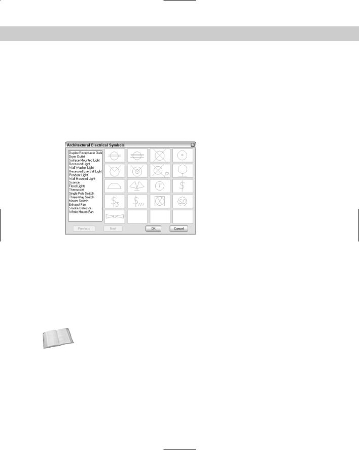
Figure 33-13 shows the resulting image-tile menu.
Figure 33-13: The Image Tile section of the menu listed previously creates this Architectural Electrical Symbols dialog box.
Tablet menus
Tablet menus are fairly straightforward. You can print out AutoCAD’s standard tablet drawing,
AutoCAD 2005\Sample\Tablet.dwg or AutoCAD LT 2005\Sample\Table Overlay.dwg, and compare it to the TABLET section of acad.mnu or aclt.mnu. The entire first section (TABLET1) is left blank for you to configure. This menu section is preset to contain 9 rows and 25 columns. If you configure this menu area (using the TABLET command) to contain 9 rows and 25 columns, you can place your own macro in each of these boxes.
Cross- |
For information on digitizing drawings and calibrating a tablet, see Chapter 16. |
Reference |
|
The TABLET2 section starts this way:
***TABLET2
**TABLET2STD // Row J View ^C^C_regen ‘_zoom _e ‘_zoom _a

976 Part VI Customizing AutoCAD
‘_zoom _w ‘_zoom _p [Draw]\ ^C^C_box ^C^C_mtext ^C^C_circle ^C^C_line ^C^C
When you configure the tablet you need to specify the number of rows and columns. The syntax of the Tablet menu is very simple; you don’t need name tags or labels, just the menu macro itself.
Note If you customize the Tablet menu, don’t forget to also open Tablet.dwg (for AutoCAD) or Tablet Overlay.dwg (for AutoCAD LT), make the corresponding changes, and print it out to overlay on your digitizer so that the drawing you place on your tablet reflects the menu properly.
Working with the Screen menu
I don’t spend much time on the Screen menu here because it’s no longer used very much. If you’re interested in customizing it, read the comments just above the ***SCREEN section of acad.mnu. AutoCAD LT doesn’t contain a Screen menu.
Tip The Screen section is very long. If you don’t use the Screen menu, you can delete it from acad.mns or the menu file you’re using. Don’t forget to back up acad.mns, or your own menu, first.
Creating status-line help messages
The ***HELPSTRINGS section of a menu file creates help messages on the status line for pulldown and toolbar menu items. This section uses the name tag of the menu item. Here is part of the HELPSTRINGS section of acad.mns. The aclt.mns HELPSTRINGS section is similar.
***HELPSTRINGS |
|
|
|
ID_2doptim |
[Set viewport to 2D wireframe: SHADEMODE] |
||
ID_3darray |
[Creates a three-dimensional array: |
3DARRAY] |
|
ID_3dclip |
[Starts 3DORBIT and opens the Adjust Clipping Planes window: 3DCLIP] |
||
ID_3dclipbk |
[Toggles the back clipping plane on or off in the 3D Orbit Adjust |
||
Clipping Planes window: |
DVIEW] |
|
|
ID_3dclipfr |
[Toggles the front clipping plane on or off in the 3D Orbit Adjust |
||
Clipping Planes window: |
DVIEW] |
|
|
ID_3dcorbit |
[Starts the 3DORBIT command with continuous orbit active in the 3D |
||
view: 3DCORBIT] |
|
|
|
ID_3ddistanc |
[Starts the 3DORBIT command and makes objects appear closer or |
||
farther away: |
3DDISTANCE] |
|
|
ID_3dface |
[Creates a three-dimensional face: |
3DFACE] |
|
ID_3dmesh |
[Creates a free-form polygon mesh: |
3DMESH] |
|
ID_3dorbit |
[Controls the interactive viewing of objects in 3D: 3DORBIT] |
||

Chapter 33 Customizing Menus 977
The help string gives the actual text that appears on the status line followed by a colon, two spaces, and the name of the command. You can follow this convention for the sake of consistency — however, some of your macros may use more than one command, so it isn’t
always appropriate. The space between the name tag and the help string is for readability only.
On the |
The file used in the following Step-by-Step exercise on creating help strings, ab2.mnu, is in |
CD-ROM |
the Drawings folder on the CD-ROM. |
|
STEP-BY-STEP: Creating Help Strings |
|
1. If you haven’t already done so, back up your menu files. |
Note |
To find the location of your menu files choose Tools Options and click the Files tab. |
|
Double-click Menu, Help, and Miscellaneous File Names (or just Miscellaneous File Names in |
|
AutoCAD LT), to display the location of the menu files. |
Caution |
Don’t continue with this exercise until you’ve completed Step 1. If you’re working on some- |
|
one else’s computer, ask permission before doing this exercise. |
2.Use Notepad to open ab2.mnu from the CD-ROM. If you did the exercise on creating a pull-down partial menu and copied ab2.mnu to your hard disk, open it from there.
3.At the top of the file, change the menugroup to AB4. Below POP1, change the name of the menu to AB4 as well.
4.Add the following lines to the end of the file and then press Enter. The name tags come from the first section of ab2.mnu but don’t include the first item, which only opens a submenu. (Each helpstring should be on one line; do not wrap to the next line in Notepad.)
***HELPSTRINGS |
|
|
|
|
|
|
ID_MoveRight |
[Moves selected objects |
.1 unit to the right] |
||||
ID_Plinewdth |
[Makes |
the width of |
one |
polyline |
.1] |
|
ID_4circles |
[Draws |
4 |
circles in |
one |
row with |
radius 1.5] |
ID_Cleanup |
[Changes |
color of all objects to |
BYLAYER, freezes |
|||
no-plot layer, and saves]
5.Save the file as ab4.mnu in your Support folder or another folder in the support-file search path. Minimize Notepad.
6.Start AutoCAD or AutoCAD LT with any template. Choose Tools Customize Menus. On the Menu Groups tab, in the File Name text box, type ab4.mnu. Making sure that Replace All is not checked. Click Load. Click Yes at the message warning you about overwriting toolbar changes.
7.Choose the Menu Bar tab. Choose Window on the Menu Bar list and click Insert. The partial menu appears to the left of the Window menu. Click Close.
8.Open the AB4 menu and place the cursor over each item, including the submenu items. The help strings appear on the status bar.
9.Unload AB4.
Don’t save your drawing.

978 Part VI Customizing AutoCAD
Creating keyboard shortcuts
The ***ACCELERATORS section creates keyboard shortcuts. Create keyboard shortcuts to speed up your work. These shortcuts search for a matching name tag and execute that name tag’s command. Here is part of the Accelerators section:
***ACCELERATORS
// Bring up hyperlink dialog ID_Hyperlink [CONTROL+”K”]
//Toggle Orthomode [CONTROL+”L”]^O
//Next Viewport [CONTROL+”R”]^V
ID_SelAll [CONTROL+”A”] ID_Copyclip [CONTROL+TOOLBAR+”C”]
ID_New |
[CONTROL+”N”] |
ID_Open |
[CONTROL+TOOLBAR+”O”] |
ID_Print |
[CONTROL+TOOLBAR+”P”] |
ID_Save |
[CONTROL+TOOLBAR+”S”] |
ID_Saveas |
[CONTROL+SHIFT+”S”] |
ID_APP_EXIT |
[CONTROL+INTERNAL+”Q”] |
ID_Pasteclip |
[CONTROL+TOOLBAR+”V”] |
ID_Copybase |
[CONTROL+SHIFT+”C”] |
ID_Pastebloc |
[CONTROL+SHIFT+”V”] |
ID_Cutclip |
[CONTROL+TOOLBAR+”X”] |
ID_Redo |
[CONTROL+”Y”] |
ID_U |
[CONTROL+”Z”] |
ID_Ai_propch |
[CONTROL+TOOLBAR+”1”] |
ID_CleanScreen |
[CONTROL+”0”] |
ID_Content |
[CONTROL+TOOLBAR+”2”] |
If a shortcut includes the word toolbar, then the shortcut only searches for toolbars with a matching name tag. If a shortcut includes the word internal, then the shortcut searches all commands listed on the Commands tab of the Customize dialog box.
Note Some of the Control shortcut codes are different in the menu than on the keyboard. For example, Ctrl+L on the keyboard is mapped to ^O in the menu (which toggles Ortho), and Ctrl+R is mapped to ^V (which moves you from one floating viewport to the next). These inconsistencies came about when Windows took over some of AutoCAD’s original keyboard shortcuts.
When you customize the menu, you can create keyboard shortcuts in two ways:
You can use a name tag, such as ID_Spell, followed by a label in brackets containing the keyboard shortcut. When you execute the shortcut, AutoCAD or AutoCAD LT looks for the name tag in the rest of the menu file and executes the command attached to that name tag.
You can start with the label containing the shortcut, such as [CONTROL+”L”], and follow it with the menu macro you want the shortcut to execute. Use this method to create shortcuts for macros that don’t exist elsewhere in the menu.
Chapter 33 Customizing Menus 979
Table 33-5 lists the expressions you need to use for all the keys you can use to create shortcuts. When you include CONTROL+ before a key, you need to hold down the Ctrl key as you press the key. You can also use SHIFT+ for the Shift key. You can also use both:
CONTROL+SHIFT+.
Caution |
In general, you should not reassign the commonly used Windows shortcuts, such as Ctrl+C |
|
(to copy data to the Clipboard), Ctrl+V (to paste data from the Clipboard), and so on. |
|
Table 33-5: Expressions for Keys in the |
|
Accelerators Section of the Menu File |
|
|
Key |
Expression |
|
|
F1 through F12 |
“F1,” “F2,” and so on |
Insert |
“INSERT” |
Delete |
“DELETE” |
Arrow keys |
“UP,” “DOWN,” “LEFT,” “RIGHT” — must be used with the Ctrl key |
Numeric keypad |
“NUMPAD0,” “NUMPAD1,” and so on through “NUMPAD9” |
|
|
Choose Tools Customize Keyboard to open the Customize dialog box with the Keyboard tab on top, shown in Figure 33-14. When you use the dialog box to create keyboard shortcuts, you can use only the function keys, Ctrl+, Ctrl+Shift+, and Ctrl+Alt+ combinations.
Figure 33-14: Use the Keyboard tab of the Customize dialog box to easily create keyboard shortcuts without having to open the menu file.
980 Part VI Customizing AutoCAD
To specify a keyboard shortcut for a command or toolbar button, follow these steps:
1.From the Categories drop-down list, choose a menu or toolbar. You can also choose AutoCAD Commands or AutoCAD LT Commands at the bottom of the list to display an alphabetical list of all commands. The choice you make determines your options; for example, the Draw menu includes many Circle and Arc options that aren’t available if you choose the Draw toolbar.
2.From the Commands drop-down list, choose the command you want to use.
3.Click the Press New Shortcut Key text box. Then use the keyboard to press the keyboard shortcut you want. For example, press F12 or Ctrl+3.
4.Click Assign.
5.If you want, continue to assign keyboard shortcuts to other commands.
6.When you’re done, click Close to close the dialog box.
Your changes are saved to the MNS file with the Menu Group specified in the Menu Group text box. In order for your shortcuts to work, the Windows Standard Accelerator Keys check box on the User Preferences tab of the Options dialog box (choose Tools Options) must be checked. (It’s checked by default.)
To remove a keyboard shortcut, click the shortcut in the Current Keys section of the Customize dialog box and click Remove. To view all your shortcuts, click Show All.
On the |
The drawing used in the following Step-by-Step exercise on creating keyboard shortcuts, |
CD-ROM |
ab5.mnu, is in the Results folder on the CD-ROM. |
STEP-BY-STEP: Creating Keyboard Shortcuts
1. If you haven’t already done so, back up your menu files.
Note To find the location of acad.mns, acad.mns, acad.mnc, acad.mnr, and acad.mnl, choose Tools Options and click the Files tab. Double-click the first item, Support File Search Path, to display the location of the support files.
Caution |
Do not continue with this exercise until you’ve completed Step 1. If you’re working on some- |
|
one else’s computer, ask permission before doing this exercise. |
2.Use Notepad to open ab4.mnu from the Results folder of the CD-ROM. If you did the previous exercise and copied ab4.mnu to your hard disk, open it from there.
3.Change the menugroup to AB5. Below POP1, change the name of the menu to AB5 as well.
4.Type the following at the end of the file and then press Enter:
***ACCELERATORS
[CONTROL+”E”]’osmode 1 [CONTROL+”8”]’osmode 7 [CONTROL+”up”]’snap 1 [CONTROL+”down”]’snap .25