

- •Foreword
- •Preface
- •Is This Book for You?
- •How This Book Is Organized
- •How to Use This Book
- •Doing the Exercises
- •Conventions Used in This Book
- •What the Icons Mean
- •About the CD-ROM
- •Other Information
- •Contacting the Author
- •Acknowledgments
- •Contents at a Glance
- •Contents
- •Getting Acquainted with AutoCAD and AutoCAD LT
- •Starting AutoCAD and AutoCAD LT
- •Creating a New Drawing
- •Using the AutoCAD and AutoCAD LT Interface
- •Creating Your First Drawing
- •Saving a Drawing
- •Summary
- •Creating a New Drawing from a Template
- •Working with Templates
- •Opening a Drawing with Default Settings
- •Opening an Existing Drawing
- •Using an Existing Drawing as a Prototype
- •Saving a Drawing Under a New Name
- •Summary
- •The Command Line
- •Command Techniques
- •Of Mice and Pucks
- •Getting Help
- •Summary
- •Typing Coordinates
- •Displaying Coordinates
- •Picking Coordinates on the Screen
- •Locating Points
- •Summary
- •Unit Types
- •Drawing Limits
- •Understanding Scales
- •Inserting a Title Block
- •Common Setup Options
- •The MVSETUP Command
- •Summary
- •Using the LINE Command
- •Drawing Rectangles
- •Drawing Polygons
- •Creating Construction Lines
- •Creating Rays
- •Summary
- •Drawing Circles
- •Drawing Arcs
- •Creating Ellipses and Elliptical Arcs
- •Making Donuts
- •Placing Points
- •Summary
- •Panning
- •The ZOOM Command
- •Aerial View
- •Named Views
- •Tiled Viewports
- •Snap Rotation
- •User Coordinate Systems
- •Isometric Drawing
- •Summary
- •Editing a Drawing
- •Selecting Objects
- •Summary
- •Copying and Moving Objects
- •Using Construction Commands
- •Creating a Revision Cloud
- •Hiding Objects with a Wipeout
- •Double-Clicking to Edit Objects
- •Grips
- •Editing with the Properties Palette
- •Selection Filters
- •Groups
- •Summary
- •Working with Layers
- •Changing Object Color, Linetype, and Lineweight
- •Working with Linetype Scales
- •Importing Layers and Linetypes from Other Drawings
- •Matching Properties
- •Summary
- •Drawing-Level Information
- •Object-Level Information
- •Measurement Commands
- •AutoCAD’s Calculator
- •Summary
- •Creating Single-Line Text
- •Understanding Text Styles
- •Creating Multiline Text
- •Creating Tables
- •Inserting Fields
- •Managing Text
- •Finding Text in Your Drawing
- •Checking Your Spelling
- •Summary
- •Working with Dimensions
- •Drawing Linear Dimensions
- •Drawing Aligned Dimensions
- •Creating Baseline and Continued Dimensions
- •Dimensioning Arcs and Circles
- •Dimensioning Angles
- •Creating Ordinate Dimensions
- •Drawing Leaders
- •Using Quick Dimension
- •Editing Dimensions
- •Summary
- •Understanding Dimension Styles
- •Defining a New Dimension Style
- •Changing Dimension Styles
- •Creating Geometric Tolerances
- •Summary
- •Creating and Editing Polylines
- •Drawing and Editing Splines
- •Creating Regions
- •Creating Boundaries
- •Creating Hatches
- •Creating and Editing Multilines
- •Creating Dlines
- •Using the SKETCH Command
- •Digitizing Drawings with the TABLET Command
- •Summary
- •Preparing a Drawing for Plotting or Printing
- •Creating a Layout in Paper Space
- •Working with Plot Styles
- •Plotting a Drawing
- •Summary
- •Combining Objects into Blocks
- •Inserting Blocks and Files into Drawings
- •Managing Blocks
- •Using Windows Features
- •Working with Attributes
- •Summary
- •Understanding External References
- •Editing an Xref within Your Drawing
- •Controlling Xref Display
- •Managing Xrefs
- •Summary
- •Preparing for Database Connectivity
- •Connecting to Your Database
- •Linking Data to Drawing Objects
- •Creating Labels
- •Querying with the Query Editor
- •Working with Query Files
- •Summary
- •Working with 3D Coordinates
- •Using Elevation and Thickness
- •Working with the User Coordinate System
- •Summary
- •Working with the Standard Viewpoints
- •Using DDVPOINT
- •Working with the Tripod and Compass
- •Getting a Quick Plan View
- •Shading Your Drawing
- •Using 3D Orbit
- •Using Tiled Viewports
- •Defining a Perspective View
- •Laying Out 3D Drawings
- •Summary
- •Drawing Surfaces with 3DFACE
- •Drawing Surfaces with PFACE
- •Creating Polygon Meshes with 3DMESH
- •Drawing Standard 3D Shapes
- •Drawing a Revolved Surface
- •Drawing an Extruded Surface
- •Drawing Ruled Surfaces
- •Drawing Edge Surfaces
- •Summary
- •Drawing Standard Shapes
- •Creating Extruded Solids
- •Drawing Revolved Solids
- •Creating Complex Solids
- •Sectioning and Slicing Solids
- •Using Editing Commands in 3D
- •Editing Solids
- •Listing Solid Properties
- •Summary
- •Understanding Rendering
- •Creating Lights
- •Creating Scenes
- •Working with Materials
- •Using Backgrounds
- •Doing the Final Render
- •Summary
- •Accessing Drawing Components with the DesignCenter
- •Accessing Drawing Content with Tool Palettes
- •Setting Standards for Drawings
- •Organizing Your Drawings
- •Working with Sheet Sets
- •Maintaining Security
- •Keeping Track of Referenced Files
- •Handling Errors and Crashes
- •Managing Drawings from Prior Releases
- •Summary
- •Importing and Exporting Other File Formats
- •Working with Raster Images
- •Pasting, Linking, and Embedding Objects
- •Summary
- •Sending Drawings
- •Opening Drawings from the Web
- •Creating Object Hyperlinks
- •Publishing Drawings
- •Summary
- •Working with Customizable Files
- •Creating Keyboard Shortcuts for Commands
- •Customizing Toolbars
- •Customizing Tool Palettes
- •Summary
- •Creating Macros with Script Files
- •Creating Slide Shows
- •Creating Slide Libraries
- •Summary
- •Creating Linetypes
- •Creating Hatch Patterns
- •Summary
- •Creating Shapes
- •Creating Fonts
- •Summary
- •Working with Menu Files
- •Customizing a Menu
- •Summary
- •Introducing Visual LISP
- •Getting Help in Visual LISP
- •Working with AutoLISP Expressions
- •Using AutoLISP on the Command Line
- •Creating AutoLISP Files
- •Summary
- •Creating Variables
- •Working with AutoCAD Commands
- •Working with Lists
- •Setting Conditions
- •Managing Drawing Objects
- •Getting Input from the User
- •Putting on the Finishing Touches
- •Summary
- •Understanding Local and Global Variables
- •Working with Visual LISP ActiveX Functions
- •Debugging Code
- •Summary
- •Starting to Work with VBA
- •Writing VBA Code
- •Getting User Input
- •Creating Dialog Boxes
- •Modifying Objects
- •Debugging and Trapping Errors
- •Moving to Advanced Programming
- •A Final Word
- •Installing AutoCAD and AutoCAD LT
- •Configuring AutoCAD
- •Starting AutoCAD Your Way
- •Configuring a Plotter
- •System Requirements
- •Using the CD with Microsoft Windows
- •What’s on the CD
- •Troubleshooting
- •Index
942 Part VI Customizing AutoCAD
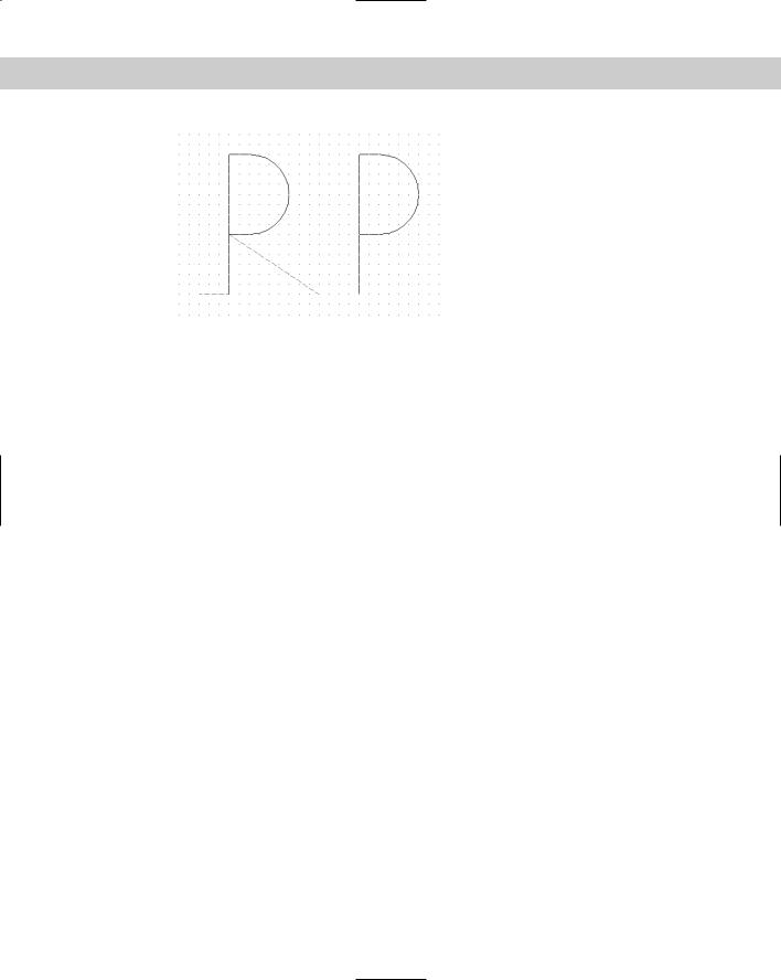
Figure 32-8: The picture and shape of the letter P.
Editing shape files
You don’t often get a shape right the first time. You don’t see the result until after you’ve compiled, loaded, and inserted the shape. Editing shape files involves the following steps:
1.Erase all copies of the shape.
2.Purge the .shx file by using the PURGE command and choosing Shapes in the dialog box. (You may sometimes need to purge more than once.) If you forget this step, when you try to insert the corrected shape, AutoCAD uses the old definition!
3.Edit the .shp file. Don’t forget to change the #ofspecs value in the first line if necessary. Save the file.
4.Recompile the .shp file.
5.Reload the .shx file.
6.Reinsert the shape using the SHAPE command.
Creating Fonts
AutoCAD’s support for TrueType fonts makes so many fonts available that the need to create your own is certainly less than with earlier versions. However, you might want to add special symbols to some existing fonts, especially if you often use these symbols within text.
Font files use the same codes to define the characters as shape files. They have the following unique characteristics:
The shapenumber part of the definition must correspond to the ASCII code value for the character you’re defining. Appendix A of the “AutoCAD Customization Guide” (choose Help Help Contents Customization Guide ASCII Codes) contains all the ASCII codes in octal, hexadecimal, and decimal formats. Fonts generally use either hexadecimal or decimal format.
The shapename part of the definition is lowercase and is usually used to label the character — for example, ucp for uppercase p and lcr for lowercase r.

Chapter 32 Creating Shapes and Fonts 943
The file must include a special shape number 0 that defines the entire font, using the following syntax:
*0,4,font-name above,below,modes,0
The above value specifies how far above the baseline uppercase letters extend. The below value specifies how far below the baseline lowercase letters, such as p or q extend. Together, these two values define the size of the characters. AutoCAD uses these values to scale letters when you define a text height for the font. Modes should be 0 for a horizontal font and 2 for a font that supports both horizontal and vertical orientations. For example, a header for a font named arch with capital letters 21 units high and lowercase letters that extend 7 units below the line could be:
*0,4,arch
21,7,0,0
You must define the line feed (LF), which drops down one line without drawing so that lines of text can be placed beneath each other. The line feed is ASCII code 10.
You need to create a start point and endpoint with the pen up to create spacing between letters. See the previous Step-by-Step exercise for an example.
As with all shapes, you probably want to use AutoCAD to draw all the characters on a grid with a spacing of 1. Decide on the height of the letters and be consistent.
Big fonts and Unicode fonts
The Japanese and Chinese written languages use fonts with thousands of characters because each character represents a word. AutoCAD uses big fonts to support these languages. It is beyond the scope of this book to go into detail about how to create these fonts, but a short explanation is useful.
Big font files use special codes to allow for the larger number of shapes. Big fonts allow up to 65,535 shape numbers. Unicode fonts support the ISO10646 standard, which uses 16-bit encoding to support many languages in one font file. If you open one of the .shp files, you’ll see characters for all the letters that may have accents in French, Spanish, and so on. All the fonts in AutoCAD are now compliant with this standard.
The advantage of Unicode fonts is that characters that you type appear the same in all systems and countries. This is important if you exchange drawings with clients or colleagues in other countries. Unicode fonts use a special header that includes two extra codes.
Unicode special characters can be inserted by typing \u+ and the hexadecimal Unicode value in the font file. (For this reason, Unicode font files use hexadecimal shape numbers.) For example, the hexadecimal code for the plus/minus sign is 00B1. If you type \u+00b1 and press Enter (using DTEXT in this example), you get the plus/minus sign. (It works with multiline text, too.)
If you don’t need the additional capabilities of big fonts or Unicode fonts, you can create fonts without them.

944 Part VI Customizing AutoCAD
Summary
In this chapter, you read about how to create shapes. You discovered how to:
Use shape files when you need to insert a shape many times, using as little storage space as possible
Create fonts using shape files with a few special codes that define both the font as a whole and each character
In the next chapter, I explain how to customize menus.
|
|
|

Customizing Menus
You probably use the AutoCAD and AutoCAD LT menus all the time. (If you don’t, you can skip this chapter.) The menus are designed to be useful for most people, but the whole point of cus-
tomization is that everyone has different needs. You can draw a lot easier and faster by customizing the menus to suit your own individual requirements. Not only can you add commands to a menu, but you can also add menu items consisting of a series of commands that run just like a macro. If you’re using AutoCAD, you can even add AutoLISP routines to your menus. You can edit the default menu or create your own menu. You may want to create specialized menus that are used only for one drawing — for example, a menu to help clients view a drawing. The only limit is your imagination — and the time you can devote to customization.
Working with Menu Files
Menu files were once simple (a long time ago). Now, under Windows, menu files are a complex subject, indeed. However, you need to understand the menu files and how they interact with each other before starting to change them.
Caution |
Don’t even think about customizing a menu until you’ve backed |
|
up at least acad.mnu or aclt.mnu. Better yet, back up all the |
|
menu files (see Table 33-1 for a listing of menu files). |
Understanding menu files
Your menu is comprised of several files in both text and compiled format. In order to customize your menus, you need to understand these files and how they work with each other. Table 33-1 lists all the menu-file types and their functions.
33C H A P T E R
In This Chapter
Understanding and working with menu files
Loading menus and partial menus
Creating commands and macros for menus
946 Part VI Customizing AutoCAD
|
Table 33-1: Menu Files and Functions |
|
|
File |
Function |
|
|
MNU |
The template menu file. AutoCAD comes with acad.mnu. AutoCAD LT comes with |
|
aclt.mnu. This is an ASCII file that you can edit. |
MNS |
The source menu file that is generated from the MNU file. It is also an ASCII file. When |
|
you customize your toolbars as described in Chapter 29, the changes go in this file. |
|
You can edit this file instead of using the MNU file to retain your toolbar |
|
customizations. |
MNC |
The compiled, binary file that the software actually uses when you choose an item on |
|
a menu. Compiled menus offer faster access. When you start AutoCAD or AutoCAD LT, |
|
if you’ve made changes in the MNS menu file, the menu is recompiled, creating a |
|
new MNC file. |
MNR |
A binary file that contains bitmaps (images) used by the menu. |
MNL |
An ASCII file that contains AutoLISP routines used by the menu. When AutoCAD |
|
loads a menu file, it automatically loads this file if it has the same filename. AutoCAD |
|
contains a number of commands that are actually AutoLISP routines — these are found |
|
in acad.mnl. AutoCAD only. |
|
|
The file types listed in Table 33-1 constitute a family of menu files. For example, AutoCAD comes with acad.mnu, acad.mns, acad.mnc, acad.mnr, and acad.mnl. AutoCAD LT comes with aclt.mnu, aclt.mns, aclt.mnc, and aclt.mnr. If you create your own menu, you create a file called, let’s say, special.mnu. From that file, AutoCAD or AutoCAD LT creates special. mns and special.mnr as a minimum. If you’re using AutoCAD, you can also place AutoLISP routines in a file called special.mnl, which will be loaded automatically whenever special. mnc is loaded. If your menu has bitmaps, AutoCAD or AutoCAD LT also creates special.mnr. You can place your menus in any folder in the support-file search path.
Note |
Remember that you can add to the support-file search path by choosing Tools Options |
|
Files tab, choosing Support File Search Path, and clicking Add. The same item shows you the |
|
current location of your menu files. |
New |
AutoCAD and AutoCAD LT now come with a separate menu, custom, that you can use for |
Feature |
your own customization. See Chapter 29 for an example of using this menu for toolbar |
|
|
|
customization. |
Loading and unloading menu files
There are two types of menus — complete and partial. A partial menu usually has only one or two pull-down menus (or toolbars). You can then load this partial menu into your regular base menu. If your menu customization consists of simply adding a few menu items, you can create a partial menu and add it to your current menu.
However, you may also want to have alternate complete menus. Perhaps two different people work on one computer and have different menu needs. Or you may find it useful to have one menu for architectural drawings, another for mechanical drawings, and a third for electrical schematics. Of course, you can customize your one full menu to better suit your needs.

Chapter 33 Customizing Menus 947
Loading a complete menu with the MENU command
To load a complete menu in AutoCAD only, you can use the MENU command at the command line. AutoCAD opens the Select Menu File dialog box, as shown in Figure 33-1.
Figure 33-1: The Select Menu File dialog box.
AutoCAD assumes that you want to load either an MNC or MNS menu file. However, you can use the Files of Type drop-down list to choose an MNU template file. You do this when you’re customizing a menu and want to recompile all the menu files that arise from the MNU file. If you’re simply loading a different menu to use, you should load either the MNC or MNS file. Select the file and click Open to load the menu.
Caution |
Loading a full menu unloads any partial menus that you might have loaded. |
When you start AutoCAD or AutoCAD LT, the last menu you used, which is stored in the Windows registry, is loaded. If you want to use a new menu while in AutoCAD or AutoCAD LT, you must load it.
Caution |
When you load an MNU file, you get a warning that loading the file will overwrite any |
|
changes you’ve made to your toolbars. To avoid this problem, either customize the MNS |
|
menu file or follow the procedure explained here. |
If you’ve customized a menu using the MNU file, here’s how you save the changes you’ve made to your toolbars while you’re customizing a menu:
1.Make the changes to the toolbars.
2.Open the MNS file of the menu you’re using. You can use Notepad to do this.
3.Select the entire toolbar section. It starts with ***TOOLBARS. Copy it to the Clipboard.
948 Part VI Customizing AutoCAD
4.Close the MNS file.
5.Open the MNU file of the same menu. (It has the same filename.)
6.Select the entire toolbar section.
7.Choose Paste from the Standard toolbar. Notepad (or your text editor) replaces the entire toolbar section with the new one from the MNS file.
8.Save the MNU file and close it.
Now your customized toolbars are incorporated into your template MNU menu file. You can customize this file as much as you like and ignore any messages about overwriting your toolbar changes.
Of course, if you make a mistake, you’ve backed up your MNU, MNS, and MNC menu files, so you can simply copy them back over the ones on your hard disk.
You can also load a complete menu with the MENULOAD command, as I discuss next.
Loading or unloading a menu with MENULOAD
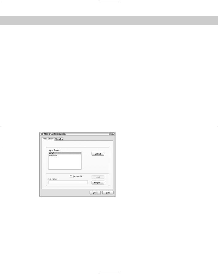
You can use the MENULOAD command to load or unload a full or a partial menu. In AutoCAD LT, you need to use this command. To load a full or partial menu, choose Tools Customize Menus. The Menu Customization dialog box (shown in Figure 33-2) opens.
Figure 33-2: The Menu Customization dialog box.
Every menu, both complete and partial, has a menu group name. The menu group name of the menu that AutoCAD comes with is ACAD. The AutoCAD LT menu is ACLT. When you create your own menus, you give them a menu group name, often (but not necessarily) the name of the file. For example, the files for the ACAD menu group are acad.mnu, acad.mns, acad.mnc, and so on.
Chapter 33 Customizing Menus 949
You can use the Menu Groups tab to load and unload full or partial menus:
To load a partial menu, type the name of the file in the File Name text box or choose Browse to locate the file. Then click Load.
To unload a loaded partial menu, choose the menu you want and click Unload. If you modify a menu, you must unload it first and then reload it.
To load a complete menu in either AutoCAD or AutoCAD LT, use the same procedure for loading a partial menu but choose a full menu. Check the Replace All check box and click Load.
Caution |
If you want to load a partial menu only, be sure that the Replace All check box is not |
|
checked. |
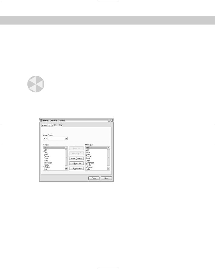
Use the Menu Bar tab, as shown in Figure 33-3, to display, hide, or reorder pull-down menus. First choose the menu group you want from the Menu Group drop-down list.
The Menus box on the left lists all the available pull-down menus. The Menu Bar list on the right displays the current order of the menu bar, from left to right.
Figure 33-3: The Menu Bar tab of the Menu
Customization dialog box.
To remove a pull-down menu, choose it from the Menu Bar list and click Remove. Click Remove All to remove all the pull-down menus.
To insert a pull-down menu, follow these steps:
1.Choose the menu from the Menu Bar list that you want your menu to be to the left of. For example, to insert the Modify menu to the left of the Dimension menu, choose Dimension.
2.Then choose the menu that you want to insert — for example, the Modify menu.
3.Click Insert.
You can move menus by using the Move Up and Move Down buttons. Click Close after you finish using the dialog box.