

- •Foreword
- •Preface
- •Is This Book for You?
- •How This Book Is Organized
- •How to Use This Book
- •Doing the Exercises
- •Conventions Used in This Book
- •What the Icons Mean
- •About the CD-ROM
- •Other Information
- •Contacting the Author
- •Acknowledgments
- •Contents at a Glance
- •Contents
- •Getting Acquainted with AutoCAD and AutoCAD LT
- •Starting AutoCAD and AutoCAD LT
- •Creating a New Drawing
- •Using the AutoCAD and AutoCAD LT Interface
- •Creating Your First Drawing
- •Saving a Drawing
- •Summary
- •Creating a New Drawing from a Template
- •Working with Templates
- •Opening a Drawing with Default Settings
- •Opening an Existing Drawing
- •Using an Existing Drawing as a Prototype
- •Saving a Drawing Under a New Name
- •Summary
- •The Command Line
- •Command Techniques
- •Of Mice and Pucks
- •Getting Help
- •Summary
- •Typing Coordinates
- •Displaying Coordinates
- •Picking Coordinates on the Screen
- •Locating Points
- •Summary
- •Unit Types
- •Drawing Limits
- •Understanding Scales
- •Inserting a Title Block
- •Common Setup Options
- •The MVSETUP Command
- •Summary
- •Using the LINE Command
- •Drawing Rectangles
- •Drawing Polygons
- •Creating Construction Lines
- •Creating Rays
- •Summary
- •Drawing Circles
- •Drawing Arcs
- •Creating Ellipses and Elliptical Arcs
- •Making Donuts
- •Placing Points
- •Summary
- •Panning
- •The ZOOM Command
- •Aerial View
- •Named Views
- •Tiled Viewports
- •Snap Rotation
- •User Coordinate Systems
- •Isometric Drawing
- •Summary
- •Editing a Drawing
- •Selecting Objects
- •Summary
- •Copying and Moving Objects
- •Using Construction Commands
- •Creating a Revision Cloud
- •Hiding Objects with a Wipeout
- •Double-Clicking to Edit Objects
- •Grips
- •Editing with the Properties Palette
- •Selection Filters
- •Groups
- •Summary
- •Working with Layers
- •Changing Object Color, Linetype, and Lineweight
- •Working with Linetype Scales
- •Importing Layers and Linetypes from Other Drawings
- •Matching Properties
- •Summary
- •Drawing-Level Information
- •Object-Level Information
- •Measurement Commands
- •AutoCAD’s Calculator
- •Summary
- •Creating Single-Line Text
- •Understanding Text Styles
- •Creating Multiline Text
- •Creating Tables
- •Inserting Fields
- •Managing Text
- •Finding Text in Your Drawing
- •Checking Your Spelling
- •Summary
- •Working with Dimensions
- •Drawing Linear Dimensions
- •Drawing Aligned Dimensions
- •Creating Baseline and Continued Dimensions
- •Dimensioning Arcs and Circles
- •Dimensioning Angles
- •Creating Ordinate Dimensions
- •Drawing Leaders
- •Using Quick Dimension
- •Editing Dimensions
- •Summary
- •Understanding Dimension Styles
- •Defining a New Dimension Style
- •Changing Dimension Styles
- •Creating Geometric Tolerances
- •Summary
- •Creating and Editing Polylines
- •Drawing and Editing Splines
- •Creating Regions
- •Creating Boundaries
- •Creating Hatches
- •Creating and Editing Multilines
- •Creating Dlines
- •Using the SKETCH Command
- •Digitizing Drawings with the TABLET Command
- •Summary
- •Preparing a Drawing for Plotting or Printing
- •Creating a Layout in Paper Space
- •Working with Plot Styles
- •Plotting a Drawing
- •Summary
- •Combining Objects into Blocks
- •Inserting Blocks and Files into Drawings
- •Managing Blocks
- •Using Windows Features
- •Working with Attributes
- •Summary
- •Understanding External References
- •Editing an Xref within Your Drawing
- •Controlling Xref Display
- •Managing Xrefs
- •Summary
- •Preparing for Database Connectivity
- •Connecting to Your Database
- •Linking Data to Drawing Objects
- •Creating Labels
- •Querying with the Query Editor
- •Working with Query Files
- •Summary
- •Working with 3D Coordinates
- •Using Elevation and Thickness
- •Working with the User Coordinate System
- •Summary
- •Working with the Standard Viewpoints
- •Using DDVPOINT
- •Working with the Tripod and Compass
- •Getting a Quick Plan View
- •Shading Your Drawing
- •Using 3D Orbit
- •Using Tiled Viewports
- •Defining a Perspective View
- •Laying Out 3D Drawings
- •Summary
- •Drawing Surfaces with 3DFACE
- •Drawing Surfaces with PFACE
- •Creating Polygon Meshes with 3DMESH
- •Drawing Standard 3D Shapes
- •Drawing a Revolved Surface
- •Drawing an Extruded Surface
- •Drawing Ruled Surfaces
- •Drawing Edge Surfaces
- •Summary
- •Drawing Standard Shapes
- •Creating Extruded Solids
- •Drawing Revolved Solids
- •Creating Complex Solids
- •Sectioning and Slicing Solids
- •Using Editing Commands in 3D
- •Editing Solids
- •Listing Solid Properties
- •Summary
- •Understanding Rendering
- •Creating Lights
- •Creating Scenes
- •Working with Materials
- •Using Backgrounds
- •Doing the Final Render
- •Summary
- •Accessing Drawing Components with the DesignCenter
- •Accessing Drawing Content with Tool Palettes
- •Setting Standards for Drawings
- •Organizing Your Drawings
- •Working with Sheet Sets
- •Maintaining Security
- •Keeping Track of Referenced Files
- •Handling Errors and Crashes
- •Managing Drawings from Prior Releases
- •Summary
- •Importing and Exporting Other File Formats
- •Working with Raster Images
- •Pasting, Linking, and Embedding Objects
- •Summary
- •Sending Drawings
- •Opening Drawings from the Web
- •Creating Object Hyperlinks
- •Publishing Drawings
- •Summary
- •Working with Customizable Files
- •Creating Keyboard Shortcuts for Commands
- •Customizing Toolbars
- •Customizing Tool Palettes
- •Summary
- •Creating Macros with Script Files
- •Creating Slide Shows
- •Creating Slide Libraries
- •Summary
- •Creating Linetypes
- •Creating Hatch Patterns
- •Summary
- •Creating Shapes
- •Creating Fonts
- •Summary
- •Working with Menu Files
- •Customizing a Menu
- •Summary
- •Introducing Visual LISP
- •Getting Help in Visual LISP
- •Working with AutoLISP Expressions
- •Using AutoLISP on the Command Line
- •Creating AutoLISP Files
- •Summary
- •Creating Variables
- •Working with AutoCAD Commands
- •Working with Lists
- •Setting Conditions
- •Managing Drawing Objects
- •Getting Input from the User
- •Putting on the Finishing Touches
- •Summary
- •Understanding Local and Global Variables
- •Working with Visual LISP ActiveX Functions
- •Debugging Code
- •Summary
- •Starting to Work with VBA
- •Writing VBA Code
- •Getting User Input
- •Creating Dialog Boxes
- •Modifying Objects
- •Debugging and Trapping Errors
- •Moving to Advanced Programming
- •A Final Word
- •Installing AutoCAD and AutoCAD LT
- •Configuring AutoCAD
- •Starting AutoCAD Your Way
- •Configuring a Plotter
- •System Requirements
- •Using the CD with Microsoft Windows
- •What’s on the CD
- •Troubleshooting
- •Index

Chapter 27 Working with Other Applications |
859 |
11.Note that the 1st row of data has a “P” in the Pur/Made column. Return to your spreadsheet and change cell F2 (which now says P) to M and press Enter. Go back to your drawing and note that the P has changed to an M. Because the data are linked, any changes made to the spreadsheet are updated in your drawing.
12.Save your drawing. Close your spreadsheet program without saving the change you made.
Summary
In this chapter, you read about the following:
Importing and exporting other file formats, including both vector and bitmap (raster) formats
Working with DXF files
Managing images and controlling their display
Pasting, linking, and embedding objects into your drawing
The next chapter discusses how to integrate AutoCAD and AutoCAD LT with the Internet.
|
|
|

Getting on the Internet
AutoCAD and AutoCAD LT offer many ways to integrate your drawings with the Internet. You can open drawings from a Web
site, hyperlink objects to anywhere on the Web, and publish drawings on a Web site. When you access a Web site (perhaps your company’s intranet), you can find blocks or other data and drag them into your drawing. This chapter covers all the ways to connect your drawings with the Internet.
Sending Drawings
You can send your drawings to others on your team or to your clients instantly — by either faxing or e-mailing them, just as you fax and e-mail other documents. You can fax a drawing if the recipient doesn’t have AutoCAD or AutoCAD LT and wants to quickly see the drawing on paper. (Later in this chapter, I explain how someone can use Autodesk DWF Viewer to view AutoCAD or AutoCAD LT drawings.)
Use e-mail if the recipient has AutoCAD or AutoCAD LT and may need to edit the drawing. You can also send a drawing to an FTP site.
Another option is to create a PDF file from the drawing and e-mail the PDF file.
Faxing a drawing
If you have fax software installed that you use to fax files from your computer, you can fax a drawing by following these steps:
1.Open the drawing you want to fax.
2.Choose File Plot. From the Printer/Plotter section of the Plot dialog box, choose the printer driver included with your fax software. Use the Fit to Paper option so your drawing fits on the recipient’s 81⁄2-x-11-inch sheet of fax paper. Choose OK.
3.Your fax software opens a dialog box to let you specify the recipient, whether to send a cover page, and so on. Choose Send or Send Fax in the dialog box to send the fax.
28C H A P T E R
In This Chapter
Faxing and e-mailing drawings
Opening drawings from the Web
Creating object hyperlinks
Publishing drawings on the World Wide Web
Creating DWF files
Viewing DWF files
862 Part V Organizing and Managing Drawings
FTPing a drawing
FTP stands for File Transfer Protocol and is a method of uploading or downloading drawings from a computer via the Internet or an intranet. You can specify FTP locations by choosing Tools Add/Modify FTP Locations from the menu of any dialog box that lets you select drawings (such as Select File or Save Drawing As). You need to list the name of the FTP site, choose a log-on type (Anonymous or User), and specify your user name and password if you’re logging on as a User. You can then open drawings from, and save them to, FTP locations.
To FTP a drawing, choose File Save As. Choose FTP, which is the last item on the Places list on the left side of the dialog box. (You may have to scroll down to see it.) Here you see FTP sites that you’ve added to the list. Select the FTP site and click Save.
E-mailing a drawing
You can e-mail a drawing from your e-mail program and include the drawing file as an attachment. Your recipient opens the attachment, automatically launching AutoCAD or AutoCAD LT. You may want to use compression software, such as PKZIP or WinZip to compress the drawing to reduce sending and receiving time.
Using eTransmit
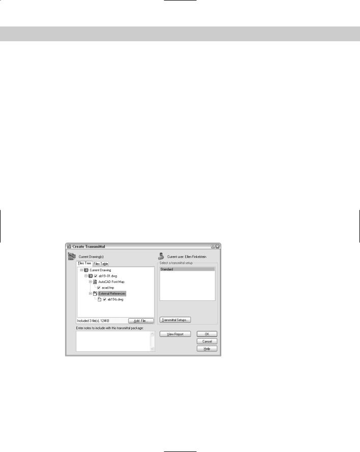
The eTransmit feature packs together all associated files with your drawing so that you can e-mail it to colleagues, clients, customers, and so on. To start a transmission, choose File eTransmit. The Create Transmittal dialog box opens, shown in Figure 28-1 with the Files Tree tab on top.
Figure 28-1: The Create Transmittal dialog box enables you to create a transmittal file that you can attach to an e-mail message. The transmittal file contains a drawing along with all its associated files.
In the Notes section, write a note to the recipient. The content of the Notes section becomes part of the transmittal report, a separate file included in the EXE or ZIP file. If you send an e-mail message, the note becomes the body of the message.
Chapter 28 Getting on the Internet 863
New |
You can now save transmittal setups and then use these setups to quickly specify the set- |
Feature |
tings you want whenever you use eTransmit. |
|
Specifying transmittal settings
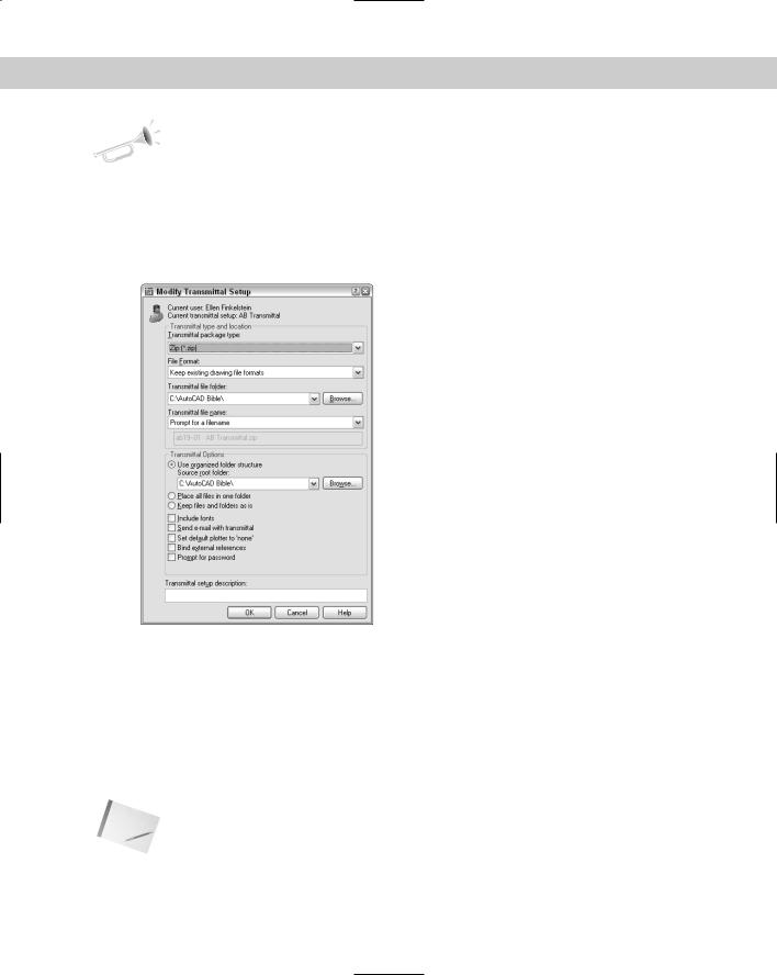
Click Transmittal Settings to open the Transmittal Setups dialog box, which lists saved setups. You can choose any saved setup. To create a new setup, click New, name the setup, and click Continue. To modify an existing setup, select the setup and click Modify. In both cases, you end up in the Modify Transmittal Setup dialog box, shown in Figure 28-2.
Figure 28-2: Use the Modify Transmittal Settings dialog box to specify how to structure your transmittal.
From the Transmittal Package Type drop-down list, choose one of the following types of transmittals:
Folder (set of files): Creates a folder that includes all the files in the transmittal. The files are not compressed.
Self-extracting executable (*.exe): Creates a compressed EXE file. Recipients can double-click the file to decompress and extract the files.
Note Some people won’t open EXE files for fear of computer viruses, so you might need to notify your recipient in advance that you’re sending the EXE file. Also, some e-mail programs block EXE attachments.
Zip (*.zip): Creates a compressed ZIP file. Recipients need WinZip, PKZIP, or a similar decompression application.

864 Part V Organizing and Managing Drawings
|
From the File Format drop-down list, you can choose to save files in earlier release formats |
|
if you want. From the Transmittal File Folder drop-down list, choose a location to save the |
|
transmittal files or click Browse to specify another location. You can leave this item blank |
|
to save the files in the same folder as the first drawing on the list in the Create Transmittal |
|
dialog box. If you’re transmitting a sheet set (AutoCAD only), the transmittal file goes in the |
|
same file as the drawing set data (DST) file. |
|
If you create an EXE or ZIP file, you can use the Transmittal File Name drop-down list to choose |
|
how you want to name the file. You can choose to be prompted for a filename, have eTransmit |
|
assign a name and overwrite any existing file with that name, or have eTransmit assign a name |
|
and increment the filename (add a number) to avoid overwriting any existing file. |
Tip |
Because you often don’t need the transmittal file after you’ve sent it (you already have all the |
|
files), you can put it in the Windows\Temp file or another location where you place files that |
|
you’ll delete. |
At the bottom of the dialog box are several Transmittal Options:
Choose one of the following folder structure options:
•Use Organized Folder Structure to create a hierarchical folder structure based on the structure of the files in the transmittal package. You can specify the root folder for this structure. When the recipient opens the transmittal package, all these folders are created.
•Place All Files in One Folder puts all the files in one folder that the recipient specifies.
•Keep Files and Folders As Is retains the exact paths of the existing files and folders.
Include Fonts includes the AutoCAD fonts in the transmittal. If your drawing only uses fonts included in a normal installation of AutoCAD or AutoCAD LT, you can probably assume that your recipients have them. TrueType fonts aren’t included because they’re proprietary.
Send E-mail with Transmittal opens your e-mail program and creates a new message with the files as attachments and the notes as the body of the message. Using this feature makes sending your drawings extremely easy.
Set Default Plotter to None removes the plotter information from the drawings, since they’re probably not useful to your recipient.
Bind External References binds xrefs to their host drawings.
Prompt for Password opens a dialog box (after you save the transmittal file) where you can specify a password. Be sure to tell your recipient the password.
At the bottom of the dialog box, you can add a description for the transmittal. Then click OK. The Transmittal Setups dialog box reappears, where you can choose the transmittal setup you want. Then click Close.