- •Foreword
- •Preface
- •Is This Book for You?
- •How This Book Is Organized
- •How to Use This Book
- •Doing the Exercises
- •Conventions Used in This Book
- •What the Icons Mean
- •About the CD-ROM
- •Other Information
- •Contacting the Author
- •Acknowledgments
- •Contents at a Glance
- •Contents
- •Getting Acquainted with AutoCAD and AutoCAD LT
- •Starting AutoCAD and AutoCAD LT
- •Creating a New Drawing
- •Using the AutoCAD and AutoCAD LT Interface
- •Creating Your First Drawing
- •Saving a Drawing
- •Summary
- •Creating a New Drawing from a Template
- •Working with Templates
- •Opening a Drawing with Default Settings
- •Opening an Existing Drawing
- •Using an Existing Drawing as a Prototype
- •Saving a Drawing Under a New Name
- •Summary
- •The Command Line
- •Command Techniques
- •Of Mice and Pucks
- •Getting Help
- •Summary
- •Typing Coordinates
- •Displaying Coordinates
- •Picking Coordinates on the Screen
- •Locating Points
- •Summary
- •Unit Types
- •Drawing Limits
- •Understanding Scales
- •Inserting a Title Block
- •Common Setup Options
- •The MVSETUP Command
- •Summary
- •Using the LINE Command
- •Drawing Rectangles
- •Drawing Polygons
- •Creating Construction Lines
- •Creating Rays
- •Summary
- •Drawing Circles
- •Drawing Arcs
- •Creating Ellipses and Elliptical Arcs
- •Making Donuts
- •Placing Points
- •Summary
- •Panning
- •The ZOOM Command
- •Aerial View
- •Named Views
- •Tiled Viewports
- •Snap Rotation
- •User Coordinate Systems
- •Isometric Drawing
- •Summary
- •Editing a Drawing
- •Selecting Objects
- •Summary
- •Copying and Moving Objects
- •Using Construction Commands
- •Creating a Revision Cloud
- •Hiding Objects with a Wipeout
- •Double-Clicking to Edit Objects
- •Grips
- •Editing with the Properties Palette
- •Selection Filters
- •Groups
- •Summary
- •Working with Layers
- •Changing Object Color, Linetype, and Lineweight
- •Working with Linetype Scales
- •Importing Layers and Linetypes from Other Drawings
- •Matching Properties
- •Summary
- •Drawing-Level Information
- •Object-Level Information
- •Measurement Commands
- •AutoCAD’s Calculator
- •Summary
- •Creating Single-Line Text
- •Understanding Text Styles
- •Creating Multiline Text
- •Creating Tables
- •Inserting Fields
- •Managing Text
- •Finding Text in Your Drawing
- •Checking Your Spelling
- •Summary
- •Working with Dimensions
- •Drawing Linear Dimensions
- •Drawing Aligned Dimensions
- •Creating Baseline and Continued Dimensions
- •Dimensioning Arcs and Circles
- •Dimensioning Angles
- •Creating Ordinate Dimensions
- •Drawing Leaders
- •Using Quick Dimension
- •Editing Dimensions
- •Summary
- •Understanding Dimension Styles
- •Defining a New Dimension Style
- •Changing Dimension Styles
- •Creating Geometric Tolerances
- •Summary
- •Creating and Editing Polylines
- •Drawing and Editing Splines
- •Creating Regions
- •Creating Boundaries
- •Creating Hatches
- •Creating and Editing Multilines
- •Creating Dlines
- •Using the SKETCH Command
- •Digitizing Drawings with the TABLET Command
- •Summary
- •Preparing a Drawing for Plotting or Printing
- •Creating a Layout in Paper Space
- •Working with Plot Styles
- •Plotting a Drawing
- •Summary
- •Combining Objects into Blocks
- •Inserting Blocks and Files into Drawings
- •Managing Blocks
- •Using Windows Features
- •Working with Attributes
- •Summary
- •Understanding External References
- •Editing an Xref within Your Drawing
- •Controlling Xref Display
- •Managing Xrefs
- •Summary
- •Preparing for Database Connectivity
- •Connecting to Your Database
- •Linking Data to Drawing Objects
- •Creating Labels
- •Querying with the Query Editor
- •Working with Query Files
- •Summary
- •Working with 3D Coordinates
- •Using Elevation and Thickness
- •Working with the User Coordinate System
- •Summary
- •Working with the Standard Viewpoints
- •Using DDVPOINT
- •Working with the Tripod and Compass
- •Getting a Quick Plan View
- •Shading Your Drawing
- •Using 3D Orbit
- •Using Tiled Viewports
- •Defining a Perspective View
- •Laying Out 3D Drawings
- •Summary
- •Drawing Surfaces with 3DFACE
- •Drawing Surfaces with PFACE
- •Creating Polygon Meshes with 3DMESH
- •Drawing Standard 3D Shapes
- •Drawing a Revolved Surface
- •Drawing an Extruded Surface
- •Drawing Ruled Surfaces
- •Drawing Edge Surfaces
- •Summary
- •Drawing Standard Shapes
- •Creating Extruded Solids
- •Drawing Revolved Solids
- •Creating Complex Solids
- •Sectioning and Slicing Solids
- •Using Editing Commands in 3D
- •Editing Solids
- •Listing Solid Properties
- •Summary
- •Understanding Rendering
- •Creating Lights
- •Creating Scenes
- •Working with Materials
- •Using Backgrounds
- •Doing the Final Render
- •Summary
- •Accessing Drawing Components with the DesignCenter
- •Accessing Drawing Content with Tool Palettes
- •Setting Standards for Drawings
- •Organizing Your Drawings
- •Working with Sheet Sets
- •Maintaining Security
- •Keeping Track of Referenced Files
- •Handling Errors and Crashes
- •Managing Drawings from Prior Releases
- •Summary
- •Importing and Exporting Other File Formats
- •Working with Raster Images
- •Pasting, Linking, and Embedding Objects
- •Summary
- •Sending Drawings
- •Opening Drawings from the Web
- •Creating Object Hyperlinks
- •Publishing Drawings
- •Summary
- •Working with Customizable Files
- •Creating Keyboard Shortcuts for Commands
- •Customizing Toolbars
- •Customizing Tool Palettes
- •Summary
- •Creating Macros with Script Files
- •Creating Slide Shows
- •Creating Slide Libraries
- •Summary
- •Creating Linetypes
- •Creating Hatch Patterns
- •Summary
- •Creating Shapes
- •Creating Fonts
- •Summary
- •Working with Menu Files
- •Customizing a Menu
- •Summary
- •Introducing Visual LISP
- •Getting Help in Visual LISP
- •Working with AutoLISP Expressions
- •Using AutoLISP on the Command Line
- •Creating AutoLISP Files
- •Summary
- •Creating Variables
- •Working with AutoCAD Commands
- •Working with Lists
- •Setting Conditions
- •Managing Drawing Objects
- •Getting Input from the User
- •Putting on the Finishing Touches
- •Summary
- •Understanding Local and Global Variables
- •Working with Visual LISP ActiveX Functions
- •Debugging Code
- •Summary
- •Starting to Work with VBA
- •Writing VBA Code
- •Getting User Input
- •Creating Dialog Boxes
- •Modifying Objects
- •Debugging and Trapping Errors
- •Moving to Advanced Programming
- •A Final Word
- •Installing AutoCAD and AutoCAD LT
- •Configuring AutoCAD
- •Starting AutoCAD Your Way
- •Configuring a Plotter
- •System Requirements
- •Using the CD with Microsoft Windows
- •What’s on the CD
- •Troubleshooting
- •Index

1096 Part VIII Appendixes
Tip To start AutoCAD with a specific profile, you can specify a profile using a command-line switch, as explained in the next section.
Starting AutoCAD Your Way
When you choose the AutoCAD icon to open AutoCAD, Windows notwithstanding, you execute a statement similar to the one old-timers once typed at the DOS prompt. This is called a com- mand-line statement. By default, it looks something like c:\Program Files\AutoCAD 2005\ acad.exe or c:\Program Files\AutoCAD LT 2005\aclt.exe. Your exact command-line statement depends on where you installed AutoCAD or AutoCAD LT.
Using command-line switches
You can add parameters, called switches, to this command line and control what happens when you start the program. Always add a space between the acad.exe or aclt.exe command and a switch. Before any switch, you can add the name of a drawing to open that drawing. You need quotation marks around any path or drawing name that contains spaces. Table A-1 lists the available command-line switches and their functions.
Table A-1: Command-Line Switches
Switch |
Example |
Function |
|
|
|
/c |
/c c:\steve\steve.cfg |
Specifies the location and, optionally, the filename of |
|
|
the hardware configuration file you want to use. |
|
|
Configuration files are discussed in the next section. |
/s |
/s c:\steve |
Specifies support folders for fonts, menus, AutoLISP |
|
|
files, linetypes, and hatch patterns. Use this when you |
|
|
want to use support files that are not in AutoCAD’s |
|
|
support-file search path. You can specify up to 15 |
|
|
folders, separated by semicolons (without spaces). |
|
|
AutoCAD only. |
/b |
“c:\drawings\Union |
Opens a drawing (here named “Union Hill Apts”) and |
|
Hill Apts.dwg” /b setup |
runs a script (here named “setup”). The full drawing |
|
|
path is required. Omit the drawing to run the script with |
|
|
a new drawing. |
/t |
/t a-tb |
Opens a new drawing based on a template file (here |
|
|
named “a-tb”). |
/nologo |
|
Starts AutoCAD without displaying the AutoCAD logo. |
|
|
AutoCAD only. |
/v |
“c:\drawings\Union |
Opens a drawing and immediately displays the specified |
|
Apts” /v front |
view (here named “front”). The full drawing path is |
|
|
required. |
/r |
/r |
Resets AutoCAD to the default configuration |
|
|
(acad2005.cfg) for the default system pointing |
|
|
device. AutoCAD only. |

Appendix A Installing and Configuring AutoCAD and AutoCAD LT 1097
Switch |
Example |
Function |
|
|
|
/p |
/p steve |
Specifies an existing profile to use when starting |
|
|
AutoCAD. This profile is used only for the current |
|
|
session. You can also change profiles using the Profile |
|
|
tab of the Options dialog box. Use quotation marks |
|
|
around the name if it contains spaces. AutoCAD only. |
/nossm |
/nossm |
Opens AutoCAD without the Sheet Set Manager. |
|
|
AutoCAD only. |
/set |
/set ab26-f |
Opens AutoCAD and the named sheet set (here called |
|
|
“ab26-f”). AutoCAD only. |
|
|
|
You can combine switches. For example, the following command-line statement opens the drawing “Union Hill Apts” in the front view and runs the setup script.
C:\Program Files\AutoCAD 2005\acad.exe “c:\drawings\Union Hill Apts.dwg” /v front /b setup
To change the command-line switch, follow these steps:
1.Right-click the shortcut to AutoCAD or AutoCAD LT on your desktop.
2.Choose Properties.
3.Click the Shortcut tab.
4.In the Target text box, add your switches to the end of the current command-line statement.
5.Click OK.
Understanding configuration files
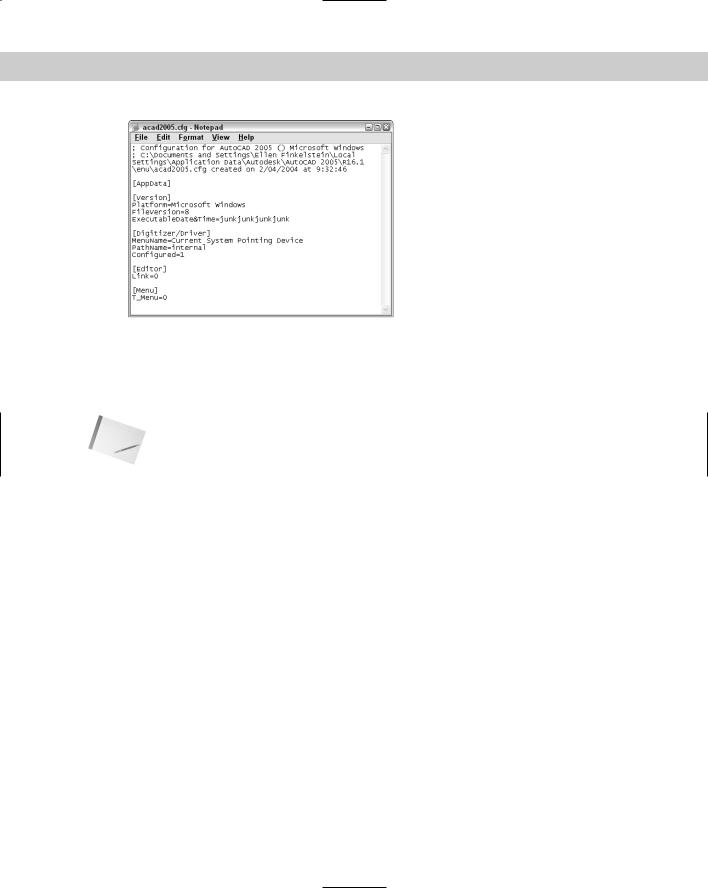
Every time you open AutoCAD, a configuration file is created. This file, acad2005.cfg (for AutoCAD) or aclt2005.cfg (for AutoCAD LT) by default, is an ASCII file containing mostly hardware-configuration information for your mouse and digitizer. Figure A-12 shows the beginning of the default file.
If you use multiple pointing devices — for example, a large and a small digitizer — you may want to create more than one configuration file to make it easy to switch from one configuration to another.
You should not edit the configuration file; instead, let AutoCAD create it for you. The problem is that AutoCAD assumes one configuration file and overwrites the previous one whenever you make changes that affect the file — such as adding a pointing device.
1098 Part VIII Appendixes
Figure A-12: The acad2005.cfg file.
Remember that you can use the /c command-line switch to specify a configuration file. To create a new file, follow these steps:
1.Use Windows Explorer to back up your current configuration file under a new name, such as acad2005-orig.cfg.
Note |
To find acad2005.cfg, choose Tools Options and click the Files tab. Double-click Menu, |
|
Help, and Miscellaneous Files, and then double-click Configuration File. I found aclt2005.cfg |
|
in C:\Documents and Settings\[username]\Local Settings\Application Data\Autodesk\ |
|
AutoCAD LT Torino\R10\enu. |
2.Open AutoCAD and make the pointer change you want on the System tab of the Options dialog box. (If you’re installing a new digitizer, follow the manufacturer’s instructions to install the digitizer.) Click OK.
3.Close AutoCAD.
4.In Explorer, find the new acad2005.cfg that AutoCAD created. Change its name, using something meaningful, such as LargeDigitizer.cfg.
5.If you want to keep the original acad2005.cfg, change its name back to acad2005.cfg.
You now have two configuration files. (You can create more if you want.) To use them, you can change the command-line switch as needed, but there’s an easier way, as explained in the next section.
Creating multiple configurations
This appendix has discussed three different ways to create session configurations:
Profiles
Configuration files
Command-line switches

Appendix A Installing and Configuring AutoCAD and AutoCAD LT 1099
You can use command-line switches to specify a profile and a configuration file as well as to configure AutoCAD in other ways — such as opening a drawing with a certain template or running a script file when you open a drawing.
If you regularly use these features, you should create multiple configurations to make it easy to open AutoCAD the way you want by doing the following:
Create the profiles and configuration files you need.
Make as many shortcuts as you need.
Note To create a new shortcut, use Explorer to find acad.exe (usually in AutoCAD 2005) or aclt.exe (usually in AutoCAD LT 2005). Right-click it and choose Create Shortcut from the menu. Drag this to your desktop and rename it.
Change the command-line switches to specify the profiles and configuration files you want, and add any other command-line switches you need.
For example, here are command lines for two separate AutoCAD desktop shortcuts. You could make similar command lines for AutoCAD LT.
C:\Program Files\AutoCAD 2005\acad.exe /t acad /nologo
C:\Program Files\AutoCAD 2005\acad.exe /p steve /c steve.cfg /t arch
The first command-line statement opens drawings using the acad.dwt template and doesn’t display the logo. It also uses the default profile and configuration file.
The second command-line statement opens drawings using the arch.dwt template and displays the logo. It also uses the steve profile and the steve configuration file.
You could also have each configuration run different script files. This technique takes some time to set up, but after it’s done it saves you time and reduces errors each time you open AutoCAD or AutoCAD LT.
Configuring a Plotter
Windows supports many printers. To add a printer supported by Windows, choose Start Settings Printers and double-click Add Printer. A printer added in this way is called a
Windows system printer.
The Windows system printer drivers are great for small desktop printers because that’s their intended use, but they aren’t optimized for pen plotters or large-format plotters. For this purpose, AutoCAD and AutoCAD LT come with nonsystem drivers. These drivers are specially designed for CAD. You cannot use them with other Windows applications.
Note |
There is a Windows system driver for DesignJet plotters created by Hewlett-Packard. See the |
|
“Installing AutoCAD and AutoCAD LT” section, earlier in this chapter, for information on |
|
installing this driver. |
1100 Part VIII Appendixes
Using the Plotter Manager
To configure a non-system plotter, use the Plotter Manager. (You can also use the Plotter Manager to create custom settings for a system printer.) You have several ways to open the Plotter Manager:
From Windows, choose Start Settings Control Panel and double-click Autodesk Plotter Manager.
From within AutoCAD or AutoCAD LT, choose File Plotter Manager.
From within AutoCAD or AutoCAD LT, choose Tools Options. On the Plot and Publish tab, click Add or Configure Plotters.
The Plotter Manager has a wizard (double-click Add-a-Plotter Wizard) that guides you through the process of configuring a printer. Follow the instructions on each page, which vary based on your previous choices.
For more information, see the “Use Plotters and Printers” section in the AutoCAD Help Installation Guide. Choose Help Help and then choose Driver and Peripheral Guide from the Contents tab.
During the process of configuring a plotter, you can import a PCP or PC2 configuration file created with an earlier release.
The result of configuring a plotter is a plotter configuration file that has a filename extension of PC3. These PC3 files are saved in the Plotters folder. (To find the PC3 files, choose Tools Options and click the Files tab. Double-click Printer Support File Path and then double-click Printer Configuration Search Path.) You can share configured plot files with colleagues or copy them to another computer, such as a notebook computer. You can configure more than one plotter. You can also create more than one configuration for a single plotter. To use a PC3 file, choose it from the Plot Device tab of the Plot dialog box.
At the end of the Plotter Manager Wizard, you can click Edit Plotter Configuration to change the default settings for your plotter. You can also click Calibrate Plotter to test that the plotter plots accurately.
Editing a plotter configuration
You can edit a plotter configuration and change its original settings. You can access the file in several ways:
As just mentioned, click Edit Plotter Configuration at the end of the Plotter Manager Wizard.
From within AutoCAD or AutoCAD LT, choose File Page Setup Manager. Click Modify. In the Page Setup dialog box, choose the plotter that you want and click Properties.
From within AutoCAD, click Plot on the Standard toolbar. Choose the plotter you want and click Properties.
From Windows Explorer, double-click a PC3 file. By default, PC3 files are in the AutoCAD 2005\Plotters folder.
A PC3 file is not an ASCII file. When you open a PC3 file, you see the Plotter Configuration Editor dialog box.

Appendix A Installing and Configuring AutoCAD and AutoCAD LT 1101
The General tab lists basic information about the plotter. This tab does not contain any options that you can configure, although you can add a description of the plotter and its settings.
The Ports tab enables you to choose to plot through a port (the usual situation), plot to a file, or use AutoSpool to plot to a printer spooler. If more than one port is available, you can choose and configure the port.
The Device and Document Settings tab contains plotting options, depending on your plotter.
As you select an item from the top part of the Plotter Configuration Editor, the appropriate options become available on the bottom of the dialog box. You can configure the following (your plotter will probably show different options):
Media: The source and size of the paper.
Physical Pen Configuration: Correction for filled areas (for extra accuracy), pen optimization for faster plotting, pen color, pen speed, and pen width.
Graphics: Color depth (the number of colors), monochrome, resolution, and dithering.
Custom properties: Vary by plotter. For Windows system printers, you might find settings such as draft printing and grayscale (for color printers).
Initialization Strings: Rarely used nowadays. If you’re plotting to an unsupported plotter, you may be able to prepare the plotter for printing, set options, and restore the plotter to its original state using ASCII text initialization strings.
User-Defined Paper Sizes and Calibration: Calibrate a plotter, create custom paper sizes, and change the plottable area of standard paper sizes.
When you finish making changes, click OK to save the changes to the PC3 files. You can also click Save As to create a new PC3 file. Click Default to return all settings to their defaults.
|
|
|