

- •Foreword
- •Preface
- •Is This Book for You?
- •How This Book Is Organized
- •How to Use This Book
- •Doing the Exercises
- •Conventions Used in This Book
- •What the Icons Mean
- •About the CD-ROM
- •Other Information
- •Contacting the Author
- •Acknowledgments
- •Contents at a Glance
- •Contents
- •Getting Acquainted with AutoCAD and AutoCAD LT
- •Starting AutoCAD and AutoCAD LT
- •Creating a New Drawing
- •Using the AutoCAD and AutoCAD LT Interface
- •Creating Your First Drawing
- •Saving a Drawing
- •Summary
- •Creating a New Drawing from a Template
- •Working with Templates
- •Opening a Drawing with Default Settings
- •Opening an Existing Drawing
- •Using an Existing Drawing as a Prototype
- •Saving a Drawing Under a New Name
- •Summary
- •The Command Line
- •Command Techniques
- •Of Mice and Pucks
- •Getting Help
- •Summary
- •Typing Coordinates
- •Displaying Coordinates
- •Picking Coordinates on the Screen
- •Locating Points
- •Summary
- •Unit Types
- •Drawing Limits
- •Understanding Scales
- •Inserting a Title Block
- •Common Setup Options
- •The MVSETUP Command
- •Summary
- •Using the LINE Command
- •Drawing Rectangles
- •Drawing Polygons
- •Creating Construction Lines
- •Creating Rays
- •Summary
- •Drawing Circles
- •Drawing Arcs
- •Creating Ellipses and Elliptical Arcs
- •Making Donuts
- •Placing Points
- •Summary
- •Panning
- •The ZOOM Command
- •Aerial View
- •Named Views
- •Tiled Viewports
- •Snap Rotation
- •User Coordinate Systems
- •Isometric Drawing
- •Summary
- •Editing a Drawing
- •Selecting Objects
- •Summary
- •Copying and Moving Objects
- •Using Construction Commands
- •Creating a Revision Cloud
- •Hiding Objects with a Wipeout
- •Double-Clicking to Edit Objects
- •Grips
- •Editing with the Properties Palette
- •Selection Filters
- •Groups
- •Summary
- •Working with Layers
- •Changing Object Color, Linetype, and Lineweight
- •Working with Linetype Scales
- •Importing Layers and Linetypes from Other Drawings
- •Matching Properties
- •Summary
- •Drawing-Level Information
- •Object-Level Information
- •Measurement Commands
- •AutoCAD’s Calculator
- •Summary
- •Creating Single-Line Text
- •Understanding Text Styles
- •Creating Multiline Text
- •Creating Tables
- •Inserting Fields
- •Managing Text
- •Finding Text in Your Drawing
- •Checking Your Spelling
- •Summary
- •Working with Dimensions
- •Drawing Linear Dimensions
- •Drawing Aligned Dimensions
- •Creating Baseline and Continued Dimensions
- •Dimensioning Arcs and Circles
- •Dimensioning Angles
- •Creating Ordinate Dimensions
- •Drawing Leaders
- •Using Quick Dimension
- •Editing Dimensions
- •Summary
- •Understanding Dimension Styles
- •Defining a New Dimension Style
- •Changing Dimension Styles
- •Creating Geometric Tolerances
- •Summary
- •Creating and Editing Polylines
- •Drawing and Editing Splines
- •Creating Regions
- •Creating Boundaries
- •Creating Hatches
- •Creating and Editing Multilines
- •Creating Dlines
- •Using the SKETCH Command
- •Digitizing Drawings with the TABLET Command
- •Summary
- •Preparing a Drawing for Plotting or Printing
- •Creating a Layout in Paper Space
- •Working with Plot Styles
- •Plotting a Drawing
- •Summary
- •Combining Objects into Blocks
- •Inserting Blocks and Files into Drawings
- •Managing Blocks
- •Using Windows Features
- •Working with Attributes
- •Summary
- •Understanding External References
- •Editing an Xref within Your Drawing
- •Controlling Xref Display
- •Managing Xrefs
- •Summary
- •Preparing for Database Connectivity
- •Connecting to Your Database
- •Linking Data to Drawing Objects
- •Creating Labels
- •Querying with the Query Editor
- •Working with Query Files
- •Summary
- •Working with 3D Coordinates
- •Using Elevation and Thickness
- •Working with the User Coordinate System
- •Summary
- •Working with the Standard Viewpoints
- •Using DDVPOINT
- •Working with the Tripod and Compass
- •Getting a Quick Plan View
- •Shading Your Drawing
- •Using 3D Orbit
- •Using Tiled Viewports
- •Defining a Perspective View
- •Laying Out 3D Drawings
- •Summary
- •Drawing Surfaces with 3DFACE
- •Drawing Surfaces with PFACE
- •Creating Polygon Meshes with 3DMESH
- •Drawing Standard 3D Shapes
- •Drawing a Revolved Surface
- •Drawing an Extruded Surface
- •Drawing Ruled Surfaces
- •Drawing Edge Surfaces
- •Summary
- •Drawing Standard Shapes
- •Creating Extruded Solids
- •Drawing Revolved Solids
- •Creating Complex Solids
- •Sectioning and Slicing Solids
- •Using Editing Commands in 3D
- •Editing Solids
- •Listing Solid Properties
- •Summary
- •Understanding Rendering
- •Creating Lights
- •Creating Scenes
- •Working with Materials
- •Using Backgrounds
- •Doing the Final Render
- •Summary
- •Accessing Drawing Components with the DesignCenter
- •Accessing Drawing Content with Tool Palettes
- •Setting Standards for Drawings
- •Organizing Your Drawings
- •Working with Sheet Sets
- •Maintaining Security
- •Keeping Track of Referenced Files
- •Handling Errors and Crashes
- •Managing Drawings from Prior Releases
- •Summary
- •Importing and Exporting Other File Formats
- •Working with Raster Images
- •Pasting, Linking, and Embedding Objects
- •Summary
- •Sending Drawings
- •Opening Drawings from the Web
- •Creating Object Hyperlinks
- •Publishing Drawings
- •Summary
- •Working with Customizable Files
- •Creating Keyboard Shortcuts for Commands
- •Customizing Toolbars
- •Customizing Tool Palettes
- •Summary
- •Creating Macros with Script Files
- •Creating Slide Shows
- •Creating Slide Libraries
- •Summary
- •Creating Linetypes
- •Creating Hatch Patterns
- •Summary
- •Creating Shapes
- •Creating Fonts
- •Summary
- •Working with Menu Files
- •Customizing a Menu
- •Summary
- •Introducing Visual LISP
- •Getting Help in Visual LISP
- •Working with AutoLISP Expressions
- •Using AutoLISP on the Command Line
- •Creating AutoLISP Files
- •Summary
- •Creating Variables
- •Working with AutoCAD Commands
- •Working with Lists
- •Setting Conditions
- •Managing Drawing Objects
- •Getting Input from the User
- •Putting on the Finishing Touches
- •Summary
- •Understanding Local and Global Variables
- •Working with Visual LISP ActiveX Functions
- •Debugging Code
- •Summary
- •Starting to Work with VBA
- •Writing VBA Code
- •Getting User Input
- •Creating Dialog Boxes
- •Modifying Objects
- •Debugging and Trapping Errors
- •Moving to Advanced Programming
- •A Final Word
- •Installing AutoCAD and AutoCAD LT
- •Configuring AutoCAD
- •Starting AutoCAD Your Way
- •Configuring a Plotter
- •System Requirements
- •Using the CD with Microsoft Windows
- •What’s on the CD
- •Troubleshooting
- •Index
500 Part III Working with Data
15.Drag the toilet into the water closet and use a Midpoint object snap to place it at the middle of the bottom wall of the water closet. If you want, choose DesignCenter on the Standard bar to close the DesignCenter (or click its Close button).
16.Do a Zoom Extents and save your drawing.
The MINSERT command (AutoCAD only) lets you insert blocks in a rectangular array. Type minsert . MINSERT prompts you for an insertion point, scale factors, and rotation angle using the same prompts as the INSERT command, without the dialog box. It then starts the same prompts as the Rectangular option of the ARRAY command, asking for the number of rows and columns and the distance between them. The value of MINSERT is that it reduces the size of your drawing because the array is one block object. The disadvantage is that you can’t edit the individual blocks in the array or the array as a whole in any way. If you need to edit them, erase the entire array of blocks, redefine the single block, if necessary, and start over, this time using DDINSERT and ARRAY separately. You cannot explode a minserted block.
Managing Blocks
Several factors require care when working with blocks. Large libraries of blocks need to be well managed so that you can find the block you need quickly. You also need to consider the issue of which layers you use when you define your blocks, so that you get the desired results when you insert them.
New |
You can now use the QSELECT command to select all instances of a block from a drop-down |
Feature |
list. Choose Block Reference as the object type, Name as the property, and from the Value |
|
|
|
drop-down list, choose the block that you want. |
Working with layers
You may want a block to take on the current layer when inserted or to retain its original layer. You can manage block layers along with their color and linetype properties to obtain the desired result. A block can be defined in four ways to determine what layer, color, linetype, and lineweight properties it will use when it’s inserted, as shown in Table 18-1. Each method has different results when the block is inserted, although some of the differences are minor.
As you can see, careful planning of the layers you use when creating a block is essential. As Table 18-1 makes clear, two of the methods (setting the objects to ByBlock and creating them on layer 0) create chameleon blocks that take on the properties of the current layer. Use the other two methods when you want the block to retain its properties regardless of the current layer.
Creating blocks on layer 0 is the simplest method. If you want the blocks to have a specific color and linetype, create a layer for them and switch to that layer before inserting the blocks. You can also change the layer of a block, after it’s inserted, in the same way that you change the layer of any object.

Chapter 18 Working with Blocks and Attributes |
501 |
Table 18-1: Properties of Block Component Objects and Insertion Results
Properties of Component Objects Insertion Results
On any layer (except layer 0), with color, lineweight, and linetype set to ByLayer
On any layer (except 0), color, linetype, and lineweight set explicitly
On any layer (except layer 0), with color, linetype, and lineweight set to ByBlock
On layer 0 (with color, linetype, and lineweight set to ByBlock or ByLayer)
The block keeps properties of that layer. If you insert a block into another drawing without that layer, the drawing creates the layer. If you insert the block into another drawing with that layer, but the layer has a different color and linetype properties, the block takes on properties of the layer that are different from those you created it on. If you insert the block on a different layer, the block keeps the properties of the layer on which it was created, but the Properties palette reports the block as being on the layer on which it was inserted, because it reports the layer of the insertion point, not the block objects.
The block keeps the color, linetype, and lineweight with properties that were explicitly set. If you insert the block into another drawing, the drawing creates the layer on which original objects were made.
The block takes on the color of the current color setting. (If the current color is set to ByLayer, the block will take on the current layer’s color.) If you insert the block into another drawing, the drawing creates the layer on which original objects were made. Note: If the color, linetype, and lineweight are ByBlock when you create objects for a block, the objects are always shown with black/ white color, a continuous linetype, and the default lineweight.
The block takes on the layer and properties of the current layer it’s inserted on. If you insert the block into another drawing, no layers are created.
On the |
The drawing that you need for the following Step-by-Step exercise on working with blocks |
CD-ROM |
and layers, ab18-d.dwg, is in the Drawings folder on the CD-ROM. |
STEP-BY-STEP: Working with Blocks and Layers
1.Open ab18-d.dwg from the CD-ROM.
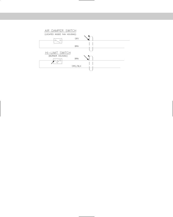
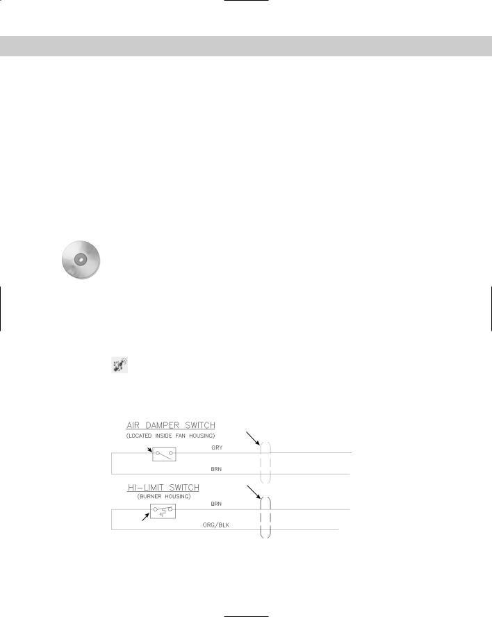
2.Save the file as ab18-04.dwg in your AutoCAD Bible folder. This is a portion of an electrical schematic, as shown in Figure 18-11. OSNAP should be on. Set running object snaps for endpoint, midpoint, quadrant, and intersection.
3.Choose Make Block from the Draw toolbar. In the Name text box of the Block Definition dialog box, type hl switch. Choose Select Objects. Use a selection window to select the entire hi-limit switch box (not including the text labels). Right-click to end selection.
Choose Pick Point in the Base Point section of the dialog box. Use the Quadrant object snap to pick the left quadrant of the left circle in the switch, at 1 in Figure 18-11. Choose Retain in the Objects section. Click OK. The objects in this block were created on the Object layer, which is red with a continuous linetype. The color, linetype, and lineweight are set to ByLayer.
502 Part III Working with Data
2
3
4
5
1
Figure 18-11: The electrical schematic has several symbols that would be useful as blocks.
4.Use a selection window to select the air damper switch. (The objects are currently on the Object layer, which is red with a continuous linetype.) Click the Color Control dropdown list and choose ByBlock. Do the same with the Linetype Control and the Lineweight Control drop-down lists. The switch turns black (or white if you’re using a black screen). The objects are still selected.
5.Choose Make Block again from the Draw toolbar. In the Name text box, type ad switch. The dialog box says 4 objects selected. Choose Pick Point. Use the Quadrant object snap to pick the left quadrant of the left circle in the switch. Click OK.
6.Use a selection window to select the top conduit symbol at 2 in Figure 18-11 (it is four objects). (It is currently on the Conduit layer, which is black and has a linetype of Hidden2.) Use the Color Control drop-down list to set the color to green. Use the Linetype Control drop-down list to set the linetype to Hidden2. Choose Make Block
from the Draw toolbar. In the Name text box, type top conduit. The dialog box tells you that four objects are selected. Choose Pick Point. Use the Intersection object snap to pick 3. Click OK. The conduit appears green with the Hidden2 linetype.
7.Use a selection window to select the bottom conduit at 4. (It is currently on the Conduit layer, which is black and has a linetype of Hidden2.) Use the Layer Control drop-down list to set the layer to 0. Choose Make Block from the Draw toolbar. In the block Name text box, type bot conduit. The dialog box tells you that four objects are selected. Choose Pick Point. Use the Intersection object snap to pick 5. Click OK. The conduit appears black with a continuous linetype.
8.Save your drawing. Choose File New. In the Select Template dialog box, click the down arrow next to the Open button. Choose one of the Open with No Template options. A new drawing opens with only one layer, layer 0. (Click the Layer Control drop-down list to check, if you want.)
9.Choose DesignCenter from the Standard toolbar. In the left pane, locate your AutoCAD Bible folder and then locate ab18-4.dwg. Double-click the drawing, and then click Blocks. In the right pane, double-click hl switch. In the Insert dialog box, check Specify On-Screen for Insertion Point and Scale. Click OK. Follow the prompts to insert the file anywhere in the drawing, using a scale factor of 3. The block, whose objects were created on the Object layer, retained its original color (red), linetype, and lineweight but is listed as being on layer 0. Select the block and look at the Layer Control drop-down list to verify this.
Chapter 18 Working with Blocks and Attributes |
503 |
10.Check the Layer Control drop-down list. A new layer, Object, is the layer that the original objects were on.
11.In the right pane of the DesignCenter, double-click top conduit. In the Insert dialog box, click OK. Follow the prompts to insert the file anywhere in the drawing, using a scale factor of 3. Again, the object retains its explicitly set properties of green color and Hidden2 linetype but is listed as being on layer 0. Click the Layer Control dropdown list to see that the Conduit layer has been added to the drawing.
12.Click the Color Control drop-down list on the Object Properties toolbar and choose Cyan to make it the current color.
13.In the DesignCenter’s right pane, double-click ad switch. In the Insert dialog box, click OK. Follow the prompts to insert the file anywhere in the drawing, using a scale factor of 3. The block (whose objects were created on the Object layer and whose properties were set to ByBlock) takes on the current color of Cyan and is listed on layer 0.
14.Choose Layer Properties Manager from the Layers toolbar and click New in the Layer Properties Manager. Name the new layer Green and set its color to Green. Click Current to make it the current layer and then click OK.
15.Double-click bot conduit. In the Insert dialog box, click OK. Follow the prompts to insert the file anywhere in the drawing, using a scale factor of 3. The block, whose original objects were on layer 0, has the properties of layer Green and is listed on layer Green.
16.Click the DesignCenter’s Close button to close the DesignCenter. Don’t save this new drawing.
Exploding blocks
You can explode blocks into their original objects. You may need to do this to edit a block. If you want, you can then redefine the block as explained earlier in this chapter.
To explode a block, choose Explode from the Modify toolbar. (You can select objects before or after choosing the command.) You can also explode polylines, dimensions, hatches, regions, multilines, and certain 3D objects (bodies, 3D meshes, 3D solids, polyface meshes, and polygon meshes) into simpler types of objects. (Drawing in 3D is covered in Part IV.) Exploding a block with nested blocks only explodes the top-level block. You need to use EXPLODE again to explode the next level of blocks.
When you explode blocks that were created on layer 0 or with BYBLOCK objects, the objects return to their original status and appear black/white with a continuous linetype and default lineweight again.
If you insert a block with different X and Y scales, the command does its best to create objects based on their new shapes. For example, if you have a block that includes a circle and insert it with an X scale of 1 and a Y scale of 2, you see an ellipse. Therefore, when you explode the block, you get an ellipse from what used to be a circle.
Using the XPLODE command
The XPLODE command is a version of the EXPLODE command that you can use to control the final layer, color, and linetype of the objects. If you select more than one object, you can set the properties for all the objects you select at once (that is, globally) or for each object individually.
504 Part III Working with Data
To xplode an object, type xplode . (XPLODE is actually an AutoLISP program in AutoCAD and is also built into AutoCAD LT.) At the Select objects: prompt, select one or more blocks. If you select more than one object, XPLODE displays the XPlode Individually/<Globally>: prompt. Right-click and choose Individually to get prompts for each block individually. Press Enter to accept the Globally default option. If you choose the Individually option, XPLODE highlights each block in turn so you know which block you’re working on as you respond to prompts.
At the Enter an option [All/Color/LAyer/LType/LWeight/Inherit from parent block/Explode] <Explode>: prompt, choose whether you want to specify color, layer, linetype, lineweight, or all four. The Color option has been updated to enable you to specify true colors using the RGB system. (See Chapter 11 for more information.) The Inherit from Parent Block option works only for blocks created on layer 0 whose color and linetype were also set to ByBlock. These ByBlock objects then retain their color and linetype after you explode them.
Xplode cannot explode blocks whose X and Y scale factors have unequal absolute values. That means an X scale of 1 and a Y scale of –1 is okay, but not an X scale of 2 and a Y scale of –3.
On the |
The drawing that you need for the following Step-by-Step exercise on exploding and xploding |
CD-ROM |
blocks, ab18-e.dwg, is in the Drawings folder on the CD-ROM. |
STEP-BY-STEP: Exploding and Xploding Blocks
1.Open ab18-e.dwg from the CD-ROM.
2.Save the file as ab18-05.dwg in your AutoCAD Bible folder. This is the same electrical schematic used in the previous exercise, except that the objects are now blocks that have been inserted (see Figure 18-12). OSNAP should be on. Set running object snaps for endpoint, midpoint, quadrant, and intersection. The current layer is Object.
3.Choose Explode from the Modify toolbar. At the Select objects: prompt, choose the air damper switch at 1 in Figure 18-12. Press Enter to end selection. The switch
turns black or white (the opposite of your screen color) because it was created from objects whose color and linetype were set to ByBlock.
4. Choose Undo from the Standard toolbar.
3
1
4
2
Figure 18-12: The electrical schematic has several blocks that have been inserted.

Chapter 18 Working with Blocks and Attributes |
505 |
5.Type xplode . At the Select objects: prompt, choose the air damper switch again. Press Enter to end selection. At the Enter an option [All/Color/LAyer/LType/ LWeight/Inherit from parent block/Explode] <Explode>: prompt, right-click
and choose Layer. At the Enter new layer name for exploded objects <OBJECT>: prompt, press Enter to accept the default of OBJECT, the current layer. The command line informs you Object exploded onto layer OBJECT.
6.Choose the hi-limit switch at 2. Choose Explode from the Modify toolbar. The command explodes the block onto the Object layer because these objects were created on that layer with their color and linetype set to ByLayer.
7.Type xplode . The top conduit was created from objects set explicitly to green color and hidden2 linetype. The bottom conduit was created from objects set to layer 0. Follow the prompts:
Select objects: Choose the conduits at 3 and 4. End selection.
2 objects found.
Xplode Individually/<Globally>: to accept the default.
Enter an option [All/Color/LAyer/LType/LWeight/Inherit from parent block/Explode] <Explode>: Right-click and choose All.
New Color [Truecolor/Colorbook] <BYLAYER>: (AutoCAD LT doesn’t
include the Truecolor/COlorbook options.)
Enter new linetype name for exploded objects <BYLAYER>: Enter new lineweight < BYLAYER >:
Enter new layer name for exploded objects <OBJECT>: conduit Objects exploded with color of BYLAYER, linetype of BYLAYER, and layer conduit.
8.Save your drawing.
Editing blocks
Blocks can be complex objects. You may need to add, remove, or change a component of a block. Here are a few additional points that can help you work with blocks.
Double-clicking to edit blocks
If you double-click a block in AutoCAD, you open the Reference Edit dialog box, which is explained in detail in Chapter 19, because it’s often used with external references. In AutoCAD LT, when you double-click a block the Properties palette opens, where you can change the block’s basic properties.
Editing blocks with grips
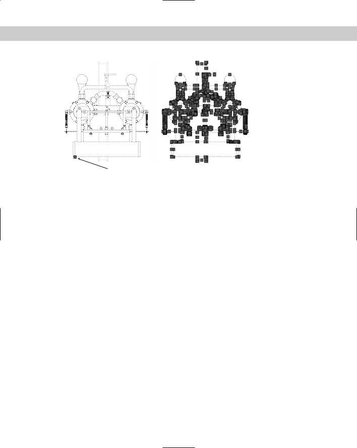
To a certain extent, you can use grip editing with blocks. By default, when you select a block, only one grip — at the base point — is displayed. However, you can show the grips of all the objects by choosing Tools Options. On the Selection tab, choose Enable Grips within Blocks and click OK. Figure 18-13 shows the results of both settings.
As a general rule, you don’t want to enable grips for blocks when working with such complex blocks. However, you can turn them on to use grips to mirror, rotate, move, or scale the block if you want to use the grip of a component object as a base point for the edit.
506 Part III Working with Data
Single grip at base point
Figure 18-13: By default, only one grip appears at the base point for a block. You can also choose to display the grips for all the component objects.
Thanks to Sid Herbage of Mississauga, Ontario, for this drawing of a quadricycle engine.
Updating blocks
As I mentioned earlier in the chapter, when you redefine a block, all instances of that block are automatically updated. However, if you inserted a file to use as a block in a drawing and then changed that file, your current drawing has no way of knowing of the change in that drawing file. (Use an external reference instead to solve this problem. See Chapter 19 for more on external references.)
To update blocks that came from inserting files, you can reinsert the file. Follow these steps:
1.Choose Insert Block.
2.Click Browse.
3.Choose the file you’ve changed and click Open. (You must locate the actual file rather than choose the block of the same name that already exists in the drawing.)
4.A message asks if you want to redefine the block because that block already exists in the drawing. Choose Yes.
5.Press Esc to avoid actually inserting a new copy of the block.
The drawing updates all the instances of the block with the new file. You can also use the DesignCenter to insert and update blocks.
Substituting blocks
You can substitute a different file as the basis for blocks in your drawing. There are three reasons for doing this:
If you have many instances of complex blocks, you may find that regen times are slow. You can create a simple block, WBLOCK it, and substitute it for the original blocks until plotting time. This is similar to using QTEXT to replace text with rectangles (see Chapter 13).
Chapter 18 Working with Blocks and Attributes |
507 |
You can create more than one version of a drawing — for example, an office layout with various kinds of desks. You can create the drawing with one type of desk, inserting files of the desks. Substitute a file of another type of desk, and you have a new office layout design.
Another common reason to substitute blocks is when your company switches to a different standard for a part.
To substitute blocks, follow these steps:
1.Type -insert on the command line.
2.Type blockname=filename where blockname is the name of the block and filename is the name of the file. (If the file is not in the support file search path, type the entire path.) Press Enter.
Note |
To place a folder in the support file search path, choose Tools Options and click the File |
|
tab. Double-click Support File Search Path. Click Add, and then type the path or browse to it. |
|
After you’re done, click OK to close the Options dialog box. |
3.A message tells you that the block with this name already exists and asks if you want to redefine it. Type y .
4.Press Esc to avoid actually inserting a new copy of the new file.
The file you inserted replaces the current blocks.
|
|
The Express Tools command, BLOCKREPLACE (choose Express Blocks Replace Block with |
|
|
Another Block) is another way to substitute blocks. Another Express Tools command, NCOPY |
|
|
(choose Express Blocks Copy Nested Objects), copies objects nested inside blocks or |
|
|
|
|
|
xrefs. XLIST (choose Express Blocks List Xref/Block Properties) lists properties of nested |
|
|
objects within blocks. SHP2BLK (choose Express Modify Convert Shape to Block) con- |
|
|
verts a shape definition to a block. |
Cross- |
For information on installing Express Tools, see Appendix A. For information on shape defini- |
|
Reference |
tions, see Chapter 32. |
|
|
|
|
Usually when you insert a file into a drawing, the block name and filename are the same. Likewise, when you WBLOCK a block, you usually name the file with the name of the block. Be aware that, when you use block substitution, you have a block in your drawing that is the same as a file of a different name. For example, if you have a block in your drawing called smalldesk and substitute a file called bigdesk, you now have a block called smalldesk that is actually the same as the file bigdesk. This can get confusing, so use block substitution with care.
On the
CD-ROM
Wb.exe unzips to three programs that create a list of blocks in your drawing and writes them to separate drawing files. Display the list of blocks and open selected drawings from the list; and, after you modify them, update those drawings as blocks in your current drawing. Wblockm also write blocks all the blocks in your drawing to a folder that you specify. Look in \Software\Chap18\Wb. These programs work with AutoCAD only. MPE-arch is a library of mechanical, plumbing, and electrical symbols for architectural drawings, mostly lights and outlets. Mpe.dwg contains all the symbols and can be used as a legend. Look in \Software\Chap18\Mpe-arch. North is a collection of North symbols for architectural drawings. Look in \Software\Chap18\North.