

- •Foreword
- •Preface
- •Is This Book for You?
- •How This Book Is Organized
- •How to Use This Book
- •Doing the Exercises
- •Conventions Used in This Book
- •What the Icons Mean
- •About the CD-ROM
- •Other Information
- •Contacting the Author
- •Acknowledgments
- •Contents at a Glance
- •Contents
- •Getting Acquainted with AutoCAD and AutoCAD LT
- •Starting AutoCAD and AutoCAD LT
- •Creating a New Drawing
- •Using the AutoCAD and AutoCAD LT Interface
- •Creating Your First Drawing
- •Saving a Drawing
- •Summary
- •Creating a New Drawing from a Template
- •Working with Templates
- •Opening a Drawing with Default Settings
- •Opening an Existing Drawing
- •Using an Existing Drawing as a Prototype
- •Saving a Drawing Under a New Name
- •Summary
- •The Command Line
- •Command Techniques
- •Of Mice and Pucks
- •Getting Help
- •Summary
- •Typing Coordinates
- •Displaying Coordinates
- •Picking Coordinates on the Screen
- •Locating Points
- •Summary
- •Unit Types
- •Drawing Limits
- •Understanding Scales
- •Inserting a Title Block
- •Common Setup Options
- •The MVSETUP Command
- •Summary
- •Using the LINE Command
- •Drawing Rectangles
- •Drawing Polygons
- •Creating Construction Lines
- •Creating Rays
- •Summary
- •Drawing Circles
- •Drawing Arcs
- •Creating Ellipses and Elliptical Arcs
- •Making Donuts
- •Placing Points
- •Summary
- •Panning
- •The ZOOM Command
- •Aerial View
- •Named Views
- •Tiled Viewports
- •Snap Rotation
- •User Coordinate Systems
- •Isometric Drawing
- •Summary
- •Editing a Drawing
- •Selecting Objects
- •Summary
- •Copying and Moving Objects
- •Using Construction Commands
- •Creating a Revision Cloud
- •Hiding Objects with a Wipeout
- •Double-Clicking to Edit Objects
- •Grips
- •Editing with the Properties Palette
- •Selection Filters
- •Groups
- •Summary
- •Working with Layers
- •Changing Object Color, Linetype, and Lineweight
- •Working with Linetype Scales
- •Importing Layers and Linetypes from Other Drawings
- •Matching Properties
- •Summary
- •Drawing-Level Information
- •Object-Level Information
- •Measurement Commands
- •AutoCAD’s Calculator
- •Summary
- •Creating Single-Line Text
- •Understanding Text Styles
- •Creating Multiline Text
- •Creating Tables
- •Inserting Fields
- •Managing Text
- •Finding Text in Your Drawing
- •Checking Your Spelling
- •Summary
- •Working with Dimensions
- •Drawing Linear Dimensions
- •Drawing Aligned Dimensions
- •Creating Baseline and Continued Dimensions
- •Dimensioning Arcs and Circles
- •Dimensioning Angles
- •Creating Ordinate Dimensions
- •Drawing Leaders
- •Using Quick Dimension
- •Editing Dimensions
- •Summary
- •Understanding Dimension Styles
- •Defining a New Dimension Style
- •Changing Dimension Styles
- •Creating Geometric Tolerances
- •Summary
- •Creating and Editing Polylines
- •Drawing and Editing Splines
- •Creating Regions
- •Creating Boundaries
- •Creating Hatches
- •Creating and Editing Multilines
- •Creating Dlines
- •Using the SKETCH Command
- •Digitizing Drawings with the TABLET Command
- •Summary
- •Preparing a Drawing for Plotting or Printing
- •Creating a Layout in Paper Space
- •Working with Plot Styles
- •Plotting a Drawing
- •Summary
- •Combining Objects into Blocks
- •Inserting Blocks and Files into Drawings
- •Managing Blocks
- •Using Windows Features
- •Working with Attributes
- •Summary
- •Understanding External References
- •Editing an Xref within Your Drawing
- •Controlling Xref Display
- •Managing Xrefs
- •Summary
- •Preparing for Database Connectivity
- •Connecting to Your Database
- •Linking Data to Drawing Objects
- •Creating Labels
- •Querying with the Query Editor
- •Working with Query Files
- •Summary
- •Working with 3D Coordinates
- •Using Elevation and Thickness
- •Working with the User Coordinate System
- •Summary
- •Working with the Standard Viewpoints
- •Using DDVPOINT
- •Working with the Tripod and Compass
- •Getting a Quick Plan View
- •Shading Your Drawing
- •Using 3D Orbit
- •Using Tiled Viewports
- •Defining a Perspective View
- •Laying Out 3D Drawings
- •Summary
- •Drawing Surfaces with 3DFACE
- •Drawing Surfaces with PFACE
- •Creating Polygon Meshes with 3DMESH
- •Drawing Standard 3D Shapes
- •Drawing a Revolved Surface
- •Drawing an Extruded Surface
- •Drawing Ruled Surfaces
- •Drawing Edge Surfaces
- •Summary
- •Drawing Standard Shapes
- •Creating Extruded Solids
- •Drawing Revolved Solids
- •Creating Complex Solids
- •Sectioning and Slicing Solids
- •Using Editing Commands in 3D
- •Editing Solids
- •Listing Solid Properties
- •Summary
- •Understanding Rendering
- •Creating Lights
- •Creating Scenes
- •Working with Materials
- •Using Backgrounds
- •Doing the Final Render
- •Summary
- •Accessing Drawing Components with the DesignCenter
- •Accessing Drawing Content with Tool Palettes
- •Setting Standards for Drawings
- •Organizing Your Drawings
- •Working with Sheet Sets
- •Maintaining Security
- •Keeping Track of Referenced Files
- •Handling Errors and Crashes
- •Managing Drawings from Prior Releases
- •Summary
- •Importing and Exporting Other File Formats
- •Working with Raster Images
- •Pasting, Linking, and Embedding Objects
- •Summary
- •Sending Drawings
- •Opening Drawings from the Web
- •Creating Object Hyperlinks
- •Publishing Drawings
- •Summary
- •Working with Customizable Files
- •Creating Keyboard Shortcuts for Commands
- •Customizing Toolbars
- •Customizing Tool Palettes
- •Summary
- •Creating Macros with Script Files
- •Creating Slide Shows
- •Creating Slide Libraries
- •Summary
- •Creating Linetypes
- •Creating Hatch Patterns
- •Summary
- •Creating Shapes
- •Creating Fonts
- •Summary
- •Working with Menu Files
- •Customizing a Menu
- •Summary
- •Introducing Visual LISP
- •Getting Help in Visual LISP
- •Working with AutoLISP Expressions
- •Using AutoLISP on the Command Line
- •Creating AutoLISP Files
- •Summary
- •Creating Variables
- •Working with AutoCAD Commands
- •Working with Lists
- •Setting Conditions
- •Managing Drawing Objects
- •Getting Input from the User
- •Putting on the Finishing Touches
- •Summary
- •Understanding Local and Global Variables
- •Working with Visual LISP ActiveX Functions
- •Debugging Code
- •Summary
- •Starting to Work with VBA
- •Writing VBA Code
- •Getting User Input
- •Creating Dialog Boxes
- •Modifying Objects
- •Debugging and Trapping Errors
- •Moving to Advanced Programming
- •A Final Word
- •Installing AutoCAD and AutoCAD LT
- •Configuring AutoCAD
- •Starting AutoCAD Your Way
- •Configuring a Plotter
- •System Requirements
- •Using the CD with Microsoft Windows
- •What’s on the CD
- •Troubleshooting
- •Index
664 Part IV Drawing in Three Dimensions
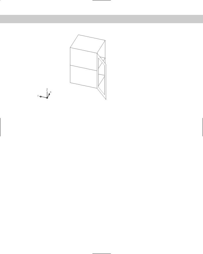
Figure 23-6: The completed kitchen cabinet, including a window in the door.
Drawing Surfaces with PFACE
PFACE draws surfaces called polyface meshes, which are a type of polyline. However, you cannot edit them with PEDIT. The best way to edit them is with grips. AutoCAD designed PFACE for the creation of surfaces using AutoLISP routines or other automated methods. Consequently, the input for polyface meshes is somewhat awkward. However, polyface meshes have the following advantages:
You can draw surfaces with any number of sides, unlike 3D faces, which can only have three or four sides.
The entire surface is one object.
Sections that are on one plane do not show edges so that you don’t have to bother with making edges invisible.
You can explode polyface meshes into 3D faces.
If you create a polyface mesh on more than one plane, each plane can be on a different layer or have a different color. This can be useful for assigning materials for rendering or other complex selection processes.
On the other hand, polyface meshes are difficult to create and edit. Figure 23-7 shows two polyface meshes — one on one plane and the other on three planes.
The prompts for PFACE are divided into two phases. The first phase simply asks for vertices. The second phase asks you to specify which vertex makes up which face (or plane). The second phase is fairly meaningless for polyface meshes on one plane, but you have to specify the vertices anyway. Here’s how to do it:

Chapter 23 Creating 3D Surfaces 665
1. Type pface .
2. At the Specify location for vertex 1: prompt, specify the first vertex.
3. Continue to specify vertices at the Specify location for vertex 2 or <define faces>: or Specify location for vertex 3 or <define faces>: prompts (and so on). Press Enter when you’ve finished.
4.At the Face 1, vertex 1: Enter a vertex number or [Color/Layer]: prompt,
type which vertex starts the first face of the polyface mesh. It’s usually vertex 1, so you type 1 .
5.At the Face 1, vertex 2: Enter a vertex number or [Color/Layer] <next face>: prompt, type which vertex comes next on the first face. Continue to specify the vertices for the first face.
If you’re drawing a polyface mesh on one plane, continue to specify all the vertices in order and press Enter twice when you’re done to end the command.
If you’re drawing a polyface mesh on more than one plane, continue to specify the vertices on the first face (that is, plane) and press Enter. At the Face 2, vertex 1: Enter a vertex number or [Color/Layer]: prompt, type the first vertex of the second face (plane) and continue to specify vertices for the second face. Press Enter. Continue to specify vertices for all the faces. Press Enter twice to end the command.
Tip |
In order to easily draw a polyface mesh with PFACE, draw 2D objects as a guide for picking |
|
vertices. Then you can use object snaps to pick the vertices. Also, for polyface meshes on |
|
more than one plane, draw a diagram that numbers the vertices. This helps you specify |
|
which vertices make up which face. |
Eight-sided polyface |
Polyface mesh |
mesh on one plane |
on three planes |
Figure 23-7: You can create many-sided polyface meshes on one plane, or on several different planes. After you use the HIDE command, the polyface mesh hides objects behind it.
666 Part IV Drawing in Three Dimensions
During the second phase of the prompts, when PFACE asks you to define the faces, you can right-click and choose Layer or Color and specify the layer or color. Then specify the vertices that are to be on that layer or color.
In the following Step-by-Step exercise, you draw a hexagonal night table with polyface meshes.
On the |
The drawing used in the following Step-by-Step exercise on drawing polyface meshes, |
CD-ROM |
ab23-b.dwg, is in the Drawings folder on the CD-ROM. |
STEP-BY-STEP: Drawing Polyface Meshes
1.Open ab23-b.dwg from the CD-ROM.
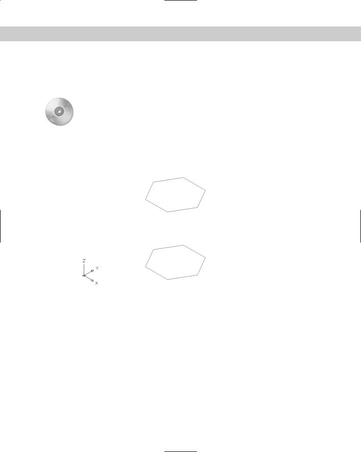
2.Save it as ab23-02.dwg in your AutoCAD Bible folder. Two hexagons have been drawn, one 24 inches above the other, on the Const layer, as shown in Figure 23-8.
4
3
5
2
6
1
0
9
!
8
@
7
Figure 23-8: The two hexagons are the basis for a night table.
3.Type pface . Follow the prompts. First you specify all the vertices. Then you specify the top hexagon, then the five sides (the front is open), and finally the bottom hexagon. Unfortunately, if you make a mistake, you must start over.
Specify location for vertex 1: Pick 1 in Figure 23-8.
Specify location for vertex 2 or <define faces>: Pick 2 in Figure 23-8.
Specify location for vertex 3 or <define faces>: Pick 3. Specify location for vertex 4 or <define faces>: Pick 4. Specify location for vertex 5 or <define faces>: Pick 5. Specify location for vertex 6 or <define faces>: Pick 6. Specify location for vertex 7 or <define faces>: Pick 7. Specify location for vertex 8 or <define faces>: Pick 8.

Chapter 23 Creating 3D Surfaces 667
Specify location for vertex 9 or <define faces>: Pick 9. Specify location for vertex 10 or <define faces>: Pick 0. Specify location for vertex 11 or <define faces>: Pick !. Specify location for vertex 12 or <define faces>: Pick @. Specify location for vertex 13 or <define faces>:
Face 1, vertex 1: Enter a vertex number or [Color/Layer]: 1 Face 1, vertex 2: Enter a vertex number or [Color/Layer] <next face>: 2
Face 1, vertex 3: Enter a vertex number or [Color/Layer] <next face>: 3
Face 1, vertex 4: Enter a vertex number or [Color/Layer] <next face>: 4
Face 1, vertex 5: Enter a vertex number or [Color/Layer] <next face>: 5
Face 1, vertex 6: Enter a vertex number or [Color/Layer] <next face>: 6
Face 1, vertex 7: Enter a vertex number or [Color/Layer] <next face>:
Face 2, vertex 1: Enter a vertex number or [Color/Layer]: 12 Face 2, vertex 2: Enter a vertex number or [Color/Layer] <next face>: 6
Face 2, vertex 3: Enter a vertex number or [Color/Layer] <next face>: 5
Face 2, vertex 4: Enter a vertex number or [Color/Layer] <next face>: 11
Face 2, vertex 5: Enter a vertex number or [Color/Layer] <next face>:
Face 3, vertex 1: Enter a vertex number or [Color/Layer]: 5 Face 3, vertex 2: Enter a vertex number or [Color/Layer] <next face>: 11
Face 3, vertex 3: Enter a vertex number or [Color/Layer] <next face>: 10
Face 3, vertex 4: Enter a vertex number or [Color/Layer] <next face>: 4
Face 3, vertex 5: Enter a vertex number or [Color/Layer] <next face>:
Face 4, vertex 1: Enter a vertex number or [Color/Layer]: 10 Face 4, vertex 2: Enter a vertex number or [Color/Layer] <next face>: 4
Face 4, vertex 3: Enter a vertex number or [Color/Layer] <next face>: 3
Face 4, vertex 4: Enter a vertex number or [Color/Layer] <next face>: 9
Face 4, vertex 5: Enter a vertex number or [Color/Layer] <next face>:
Face 5, vertex 1: Enter a vertex number or [Color/Layer]: 3 Face 5, vertex 2: Enter a vertex number or [Color/Layer] <next face>: 9
Face 5, vertex 3: Enter a vertex number or [Color/Layer] <next face>: 8
668 Part IV Drawing in Three Dimensions
Face 5, vertex 4: Enter a vertex number or [Color/Layer] <next face>: 2
Face 5, vertex 5: Enter a vertex number or [Color/Layer] <next face>:
Face 6, vertex 1: Enter a vertex number or [Color/Layer]: 8 Face 6, vertex 2: Enter a vertex number or [Color/Layer] <next face>: 2
Face 6, vertex 3: Enter a vertex number or [Color/Layer] <next face>: 1
Face 6, vertex 4: Enter a vertex number or [Color/Layer] <next face>: 7
Face 6, vertex 5: Enter a vertex number or [Color/Layer] <next face>:
Face 7, vertex 1: Enter a vertex number or [Color/Layer]: 7 Face 7, vertex 2: Enter a vertex number or [Color/Layer] <next face>: 8
Face 7, vertex 3: Enter a vertex number or [Color/Layer] <next face>: 9
Face 7, vertex 4: Enter a vertex number or [Color/Layer] <next face>: 10
Face 7, vertex 5: Enter a vertex number or [Color/Layer] <next face>: 11
Face 7, vertex 6: Enter a vertex number or [Color/Layer] <next face>: 12
Face 7, vertex 7: Enter a vertex number or [Color/Layer] <next face>:
Face 8, vertex 1: Enter a vertex number or [Color/Layer]:
4.Choose View Hide to see the final result.
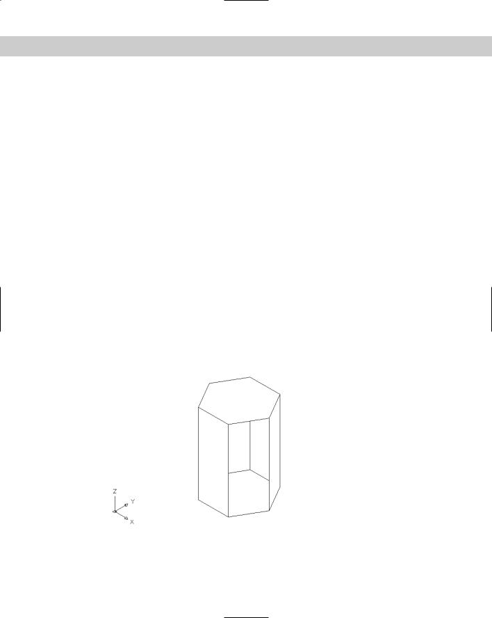
5.Save your drawing. It should look like Figure 23-9.
Figure 23-9: The completed hexagonal night table.