

- •Foreword
- •Preface
- •Is This Book for You?
- •How This Book Is Organized
- •How to Use This Book
- •Doing the Exercises
- •Conventions Used in This Book
- •What the Icons Mean
- •About the CD-ROM
- •Other Information
- •Contacting the Author
- •Acknowledgments
- •Contents at a Glance
- •Contents
- •Getting Acquainted with AutoCAD and AutoCAD LT
- •Starting AutoCAD and AutoCAD LT
- •Creating a New Drawing
- •Using the AutoCAD and AutoCAD LT Interface
- •Creating Your First Drawing
- •Saving a Drawing
- •Summary
- •Creating a New Drawing from a Template
- •Working with Templates
- •Opening a Drawing with Default Settings
- •Opening an Existing Drawing
- •Using an Existing Drawing as a Prototype
- •Saving a Drawing Under a New Name
- •Summary
- •The Command Line
- •Command Techniques
- •Of Mice and Pucks
- •Getting Help
- •Summary
- •Typing Coordinates
- •Displaying Coordinates
- •Picking Coordinates on the Screen
- •Locating Points
- •Summary
- •Unit Types
- •Drawing Limits
- •Understanding Scales
- •Inserting a Title Block
- •Common Setup Options
- •The MVSETUP Command
- •Summary
- •Using the LINE Command
- •Drawing Rectangles
- •Drawing Polygons
- •Creating Construction Lines
- •Creating Rays
- •Summary
- •Drawing Circles
- •Drawing Arcs
- •Creating Ellipses and Elliptical Arcs
- •Making Donuts
- •Placing Points
- •Summary
- •Panning
- •The ZOOM Command
- •Aerial View
- •Named Views
- •Tiled Viewports
- •Snap Rotation
- •User Coordinate Systems
- •Isometric Drawing
- •Summary
- •Editing a Drawing
- •Selecting Objects
- •Summary
- •Copying and Moving Objects
- •Using Construction Commands
- •Creating a Revision Cloud
- •Hiding Objects with a Wipeout
- •Double-Clicking to Edit Objects
- •Grips
- •Editing with the Properties Palette
- •Selection Filters
- •Groups
- •Summary
- •Working with Layers
- •Changing Object Color, Linetype, and Lineweight
- •Working with Linetype Scales
- •Importing Layers and Linetypes from Other Drawings
- •Matching Properties
- •Summary
- •Drawing-Level Information
- •Object-Level Information
- •Measurement Commands
- •AutoCAD’s Calculator
- •Summary
- •Creating Single-Line Text
- •Understanding Text Styles
- •Creating Multiline Text
- •Creating Tables
- •Inserting Fields
- •Managing Text
- •Finding Text in Your Drawing
- •Checking Your Spelling
- •Summary
- •Working with Dimensions
- •Drawing Linear Dimensions
- •Drawing Aligned Dimensions
- •Creating Baseline and Continued Dimensions
- •Dimensioning Arcs and Circles
- •Dimensioning Angles
- •Creating Ordinate Dimensions
- •Drawing Leaders
- •Using Quick Dimension
- •Editing Dimensions
- •Summary
- •Understanding Dimension Styles
- •Defining a New Dimension Style
- •Changing Dimension Styles
- •Creating Geometric Tolerances
- •Summary
- •Creating and Editing Polylines
- •Drawing and Editing Splines
- •Creating Regions
- •Creating Boundaries
- •Creating Hatches
- •Creating and Editing Multilines
- •Creating Dlines
- •Using the SKETCH Command
- •Digitizing Drawings with the TABLET Command
- •Summary
- •Preparing a Drawing for Plotting or Printing
- •Creating a Layout in Paper Space
- •Working with Plot Styles
- •Plotting a Drawing
- •Summary
- •Combining Objects into Blocks
- •Inserting Blocks and Files into Drawings
- •Managing Blocks
- •Using Windows Features
- •Working with Attributes
- •Summary
- •Understanding External References
- •Editing an Xref within Your Drawing
- •Controlling Xref Display
- •Managing Xrefs
- •Summary
- •Preparing for Database Connectivity
- •Connecting to Your Database
- •Linking Data to Drawing Objects
- •Creating Labels
- •Querying with the Query Editor
- •Working with Query Files
- •Summary
- •Working with 3D Coordinates
- •Using Elevation and Thickness
- •Working with the User Coordinate System
- •Summary
- •Working with the Standard Viewpoints
- •Using DDVPOINT
- •Working with the Tripod and Compass
- •Getting a Quick Plan View
- •Shading Your Drawing
- •Using 3D Orbit
- •Using Tiled Viewports
- •Defining a Perspective View
- •Laying Out 3D Drawings
- •Summary
- •Drawing Surfaces with 3DFACE
- •Drawing Surfaces with PFACE
- •Creating Polygon Meshes with 3DMESH
- •Drawing Standard 3D Shapes
- •Drawing a Revolved Surface
- •Drawing an Extruded Surface
- •Drawing Ruled Surfaces
- •Drawing Edge Surfaces
- •Summary
- •Drawing Standard Shapes
- •Creating Extruded Solids
- •Drawing Revolved Solids
- •Creating Complex Solids
- •Sectioning and Slicing Solids
- •Using Editing Commands in 3D
- •Editing Solids
- •Listing Solid Properties
- •Summary
- •Understanding Rendering
- •Creating Lights
- •Creating Scenes
- •Working with Materials
- •Using Backgrounds
- •Doing the Final Render
- •Summary
- •Accessing Drawing Components with the DesignCenter
- •Accessing Drawing Content with Tool Palettes
- •Setting Standards for Drawings
- •Organizing Your Drawings
- •Working with Sheet Sets
- •Maintaining Security
- •Keeping Track of Referenced Files
- •Handling Errors and Crashes
- •Managing Drawings from Prior Releases
- •Summary
- •Importing and Exporting Other File Formats
- •Working with Raster Images
- •Pasting, Linking, and Embedding Objects
- •Summary
- •Sending Drawings
- •Opening Drawings from the Web
- •Creating Object Hyperlinks
- •Publishing Drawings
- •Summary
- •Working with Customizable Files
- •Creating Keyboard Shortcuts for Commands
- •Customizing Toolbars
- •Customizing Tool Palettes
- •Summary
- •Creating Macros with Script Files
- •Creating Slide Shows
- •Creating Slide Libraries
- •Summary
- •Creating Linetypes
- •Creating Hatch Patterns
- •Summary
- •Creating Shapes
- •Creating Fonts
- •Summary
- •Working with Menu Files
- •Customizing a Menu
- •Summary
- •Introducing Visual LISP
- •Getting Help in Visual LISP
- •Working with AutoLISP Expressions
- •Using AutoLISP on the Command Line
- •Creating AutoLISP Files
- •Summary
- •Creating Variables
- •Working with AutoCAD Commands
- •Working with Lists
- •Setting Conditions
- •Managing Drawing Objects
- •Getting Input from the User
- •Putting on the Finishing Touches
- •Summary
- •Understanding Local and Global Variables
- •Working with Visual LISP ActiveX Functions
- •Debugging Code
- •Summary
- •Starting to Work with VBA
- •Writing VBA Code
- •Getting User Input
- •Creating Dialog Boxes
- •Modifying Objects
- •Debugging and Trapping Errors
- •Moving to Advanced Programming
- •A Final Word
- •Installing AutoCAD and AutoCAD LT
- •Configuring AutoCAD
- •Starting AutoCAD Your Way
- •Configuring a Plotter
- •System Requirements
- •Using the CD with Microsoft Windows
- •What’s on the CD
- •Troubleshooting
- •Index
330 Part II Drawing in Two Dimensions
9.Again choose Multiline Text from the Draw toolbar. Pick two boundary points within the Date box of the title block. In the Multiline Text Editor, right-click and choose Insert Field.
10.From the Field Category drop-down list, choose Date & Time. From the Field Names list, choose CreateDate. From the Format list, choose M/d/yy. Click OK. Click anywhere outside the Multiline Text Editor to place the field.
11.Save your drawing. The title block should look like Figure 13-28.
Figure 13-28: The title block after adding some fields.
Managing Text
Text is a complex object type. Text greatly increases drawing size and adds redraw and regeneration time. The more-complex fonts, such as the TrueType fonts, can have a huge impact on how long it takes to open and save a file. The techniques described in this section help you manage text and improve performance while editing your drawing.
Using Quicktext
The QTEXT command replaces all text with rectangles that approximate the placement of the original text, as shown in Figure 13-29. All text objects, including dimensions, attributes, and tolerances, are affected. To use QTEXT, type qtext on the command line. Type on to get the rectangles; type off to return to regular text. Then type regen at the command line. Quicktext takes effect only after a regeneration; it does not apply to OLE objects that you have pasted into a drawing from the Windows Clipboard (see Chapter 27).
Using AutoCAD and AutoCAD LT fonts
AutoCAD and AutoCAD LT fonts are simpler than TrueType fonts, and some fonts are simpler than others. The simplest font is txt.shx, the font used by the default Standard text style. You can easily define a text style using an AutoCAD or AutoCAD LT font and then change the font to something nicer just before plotting. Be aware that the text may take up more or less space than before.
When your drawing cannot find the specified font, it uses an alternate font. This may happen if you receive a drawing done by someone else that uses a custom or third-party font that you don’t have. You can specify the alternate font by choosing Tools Options and clicking the plus sign next to Text Editor, Dictionary, and Font File Names on the Files tab. Choose Alternate Font File to specify the alternate font, which is simplex.shx by default.
Chapter 13 Creating Text 331
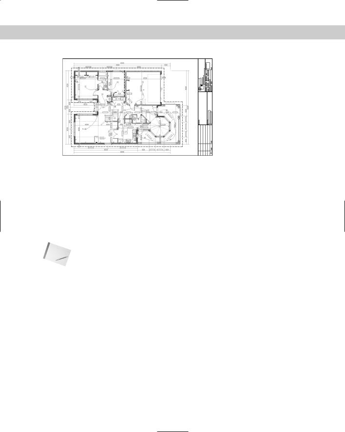
Figure 13-29: A drawing with QTEXT on. Rectangles have replaced all the text.
Thanks to Rod Greer of R. G. Greer Design, Inc., Fergus, Ontario, for this drawing.
You can further control the fonts used in your drawing by customizing the Font Mapping File,
\acad.fmp. The format is current_font; font_to_substitute. (You need to use the actual filenames of the fonts.) To substitute a simpler font for the Arial Black font, you could add the following line:
Ariblk.ttf;simplex.shx
To find the Windows TrueType fonts, look in the Fonts subfolder of your Windows folder.
Note |
To find acad.fmp, choose Tools Options and click the File tab. Double-click Text Editor, |
|
Dictionary, and Font File Names. Double-click Font Mapping File. Click the path list to view |
|
the location of acad.fmp. AutoCAD and AutoCAD LT only read the font-mapping file when |
|
you open a new drawing, so that any changes you make are effective only after you start a |
|
new drawing. |
Freezing text layers
Freezing text layers can help regeneration time dramatically — a good reason to give text its own layer. Don’t forget to freeze dimension text, too. Dimensions are usually placed on a separate layer (see Chapter 14).
Using MIRRTEXT
When you mirror sections of your drawing that include text, you usually don’t want any backward text (unless you’re Alice going through the looking glass). The MIRRTEXT system variable controls whether text is mirrored or retains its normal orientation. The default value for MIRRTEXT is off, so that mirrored text is not backward. The text is copied to the mirrored location, but reads from left to right (if that’s the direction of the language you’re using).
332 Part II Drawing in Two Dimensions
If you do want to mirror the text, type mirrtext . At the New value for MIRRTEXT <0>: prompt, type 1 to turn MIRRTEXT on. This system variable is saved with the drawing, so you may still need to change it when you open older drawings.
On the |
The drawing used in the following Step-by-Step exercise on managing text, ab13-e.dwg, is |
CD-ROM |
in the Drawings folder on the CD-ROM. |
STEP-BY-STEP: Managing Text
1.Open ab13-e.dwg from your CD-ROM.
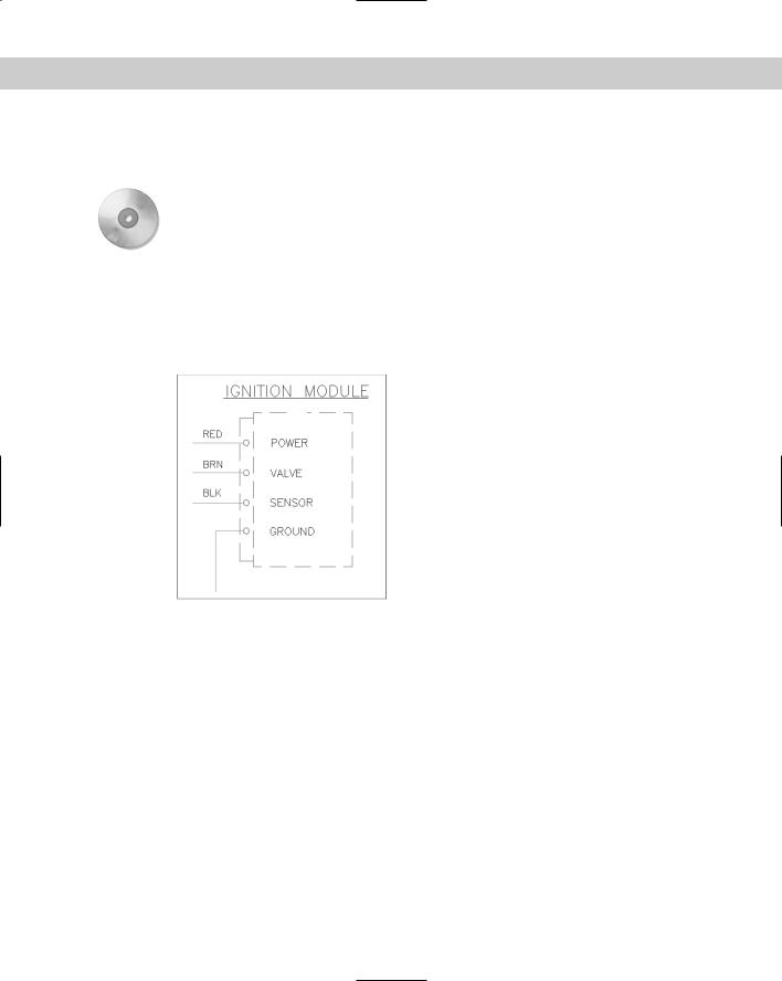
2.Save the file as ab13-08.dwg in your AutoCAD Bible folder. This is a small section of an electrical schematic, as shown in Figure 13-30. Make sure ORTHO and OSNAP are on, and set running snaps for endpoint, midpoint, and intersection.
1
Figure 13-30: A section of an electrical schematic.
3
2
3.Type qtext . At the Enter mode [ON/OFF] <OFF>: prompt, type on_ . Type regen . The command replaces the text with rectangles.
4.Type qtext . At the Enter mode [ON/OFF] <ON>: prompt, type off . Type regen . Your original text reappears.
5.Start the MIRROR command. Follow the prompts:
Select objects: Start a window by picking 2 in Figure 13-21. Specify opposite corner: Pick 1. Press Enter to end object selection.
Specify first point of mirror line: Use the Midpoint running object snap to pick the midpoint at 3.
Specify second point of mirror line: Pick any point vertical to the
first point.
Delete source objects? [Yes/No] <N>:
The command mirrors the objects and the text, because the MIRRTEXT system variable was set to 1. The text is backward.
Chapter 13 Creating Text 333
6.Choose Undo from the Standard toolbar.
7.Type mirrtext . At the Enter new value for MIRRTEXT <1>: prompt, type 0 .
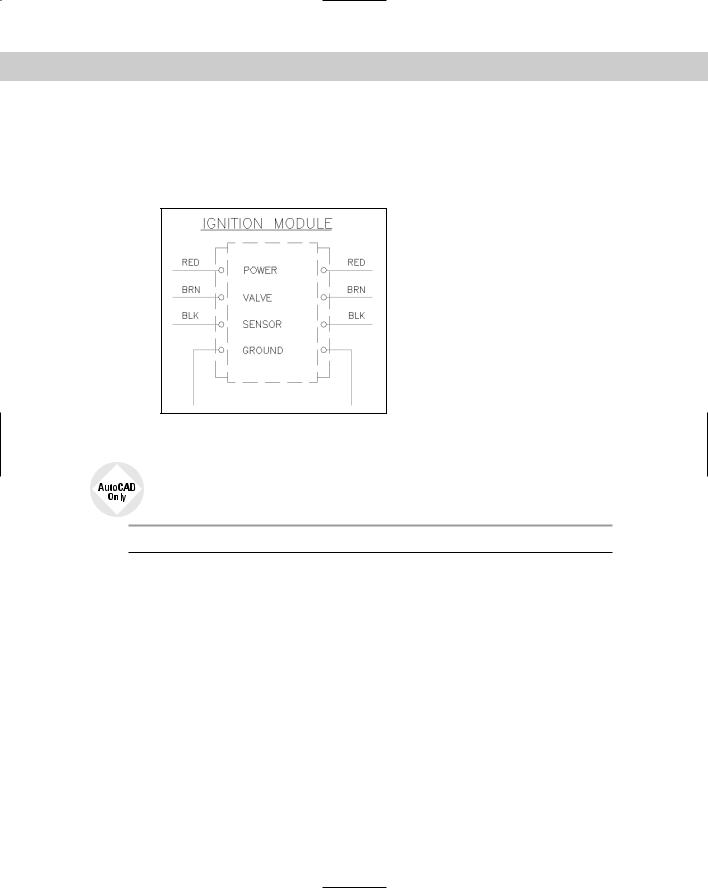
8.Repeat the mirror operation using the same instructions as in Step 5. This time the command mirrors the objects, but the text reads properly, as shown in Figure 13-31.
Figure 13-31: The text on the right was mirrored with MIRRTEXT set to 0.
9. Save your drawing.
Express Tools has a number of text routines that you may find very helpful. Table 13-3 lists these tools. See Appendix A for information on installing Express Tools.
Table 13-3: Express Tools for Text
Command |
Menu |
Description |
|
|
|
RTEXT |
Express Text Remote Text |
Displays text from an outside file. You can specify the |
|
|
text style, height, and rotation. Use RTEDIT on the |
|
|
command line to edit remote text. |
TEXTFIT |
Express Text Text Fit |
Stretches or shrinks Text objects (but not MText) to fit |
|
|
between two points. |
TEXTMASK |
Express Text Text Mask |
Creates a wipeout, 3D face, or 2D solid object behind |
|
|
the text with a little extra space around the text. You |
|
|
can use this to make text on top of a hatch more |
|
|
legible. |
TEXTUNMASK |
Express Text Text Unmask |
Removes a text mask. |
TXTEXP |
Express Text Explode Text |
Transforms Text or Mtext into geometrical shapes. |
TXT2MTXT |
Express Text Convert Text |
Converts Text objects to Mtext objects. |
|
to MText |
|
Continued