

- •Preface
- •About This Book
- •Acknowledgments
- •Contents at a Glance
- •Contents
- •Relaxing at the Beach
- •Dressing the Scene
- •Animating Motion
- •Rendering the Final Animation
- •Summary
- •The Interface Elements
- •Using the Menus
- •Using the Toolbars
- •Using the Viewports
- •Using the Command Panel
- •Using the Lower Interface Bar Controls
- •Interacting with the Interface
- •Getting Help
- •Summary
- •Understanding 3D Space
- •Using the Viewport Navigation Controls
- •Configuring the Viewports
- •Working with Viewport Backgrounds
- •Summary
- •Working with Max Scene Files
- •Setting File Preferences
- •Importing and Exporting
- •Referencing External Objects
- •Using the File Utilities
- •Accessing File Information
- •Summary
- •Customizing Modify and Utility Panel Buttons
- •Working with Custom Interfaces
- •Configuring Paths
- •Selecting System Units
- •Setting Preferences
- •Summary
- •Creating Primitive Objects
- •Exploring the Primitive Object Types
- •Summary
- •Selecting Objects
- •Setting Object Properties
- •Hiding and Freezing Objects
- •Using Layers
- •Summary
- •Cloning Objects
- •Understanding Cloning Options
- •Mirroring Objects
- •Cloning over Time
- •Spacing Cloned Objects
- •Creating Arrays of Objects
- •Summary
- •Working with Groups
- •Building Assemblies
- •Building Links between Objects
- •Displaying Links and Hierarchies
- •Working with Linked Objects
- •Summary
- •Using the Schematic View Window
- •Working with Hierarchies
- •Setting Schematic View Preferences
- •Using List Views
- •Summary
- •Working with the Transformation Tools
- •Using Pivot Points
- •Using the Align Commands
- •Using Grids
- •Using Snap Options
- •Summary
- •Exploring the Modifier Stack
- •Exploring Modifier Types
- •Summary
- •Exploring the Modeling Types
- •Working with Subobjects
- •Modeling Helpers
- •Summary
- •Drawing in 2D
- •Editing Splines
- •Using Spline Modifiers
- •Summary
- •Creating Editable Mesh and Poly Objects
- •Editing Mesh Objects
- •Editing Poly Objects
- •Using Mesh Editing Modifiers
- •Summary
- •Introducing Patch Grids
- •Editing Patches
- •Using Modifiers on Patch Objects
- •Summary
- •Creating NURBS Curves and Surfaces
- •Editing NURBS
- •Working with NURBS
- •Summary
- •Morphing Objects
- •Creating Conform Objects
- •Creating a ShapeMerge Object
- •Creating a Terrain Object
- •Using the Mesher Object
- •Working with BlobMesh Objects
- •Creating a Scatter Object
- •Creating Connect Objects
- •Modeling with Boolean Objects
- •Creating a Loft Object
- •Summary
- •Understanding the Various Particle Systems
- •Creating a Particle System
- •Using the Spray and Snow Particle Systems
- •Using the Super Spray Particle System
- •Using the Blizzard Particle System
- •Using the PArray Particle System
- •Using the PCloud Particle System
- •Using Particle System Maps
- •Controlling Particles with Particle Flow
- •Summary
- •Understanding Material Properties
- •Working with the Material Editor
- •Using the Material/Map Browser
- •Using the Material/Map Navigator
- •Summary
- •Using the Standard Material
- •Using Shading Types
- •Accessing Other Parameters
- •Using External Tools
- •Summary
- •Using Compound Materials
- •Using Raytrace Materials
- •Using the Matte/Shadow Material
- •Using the DirectX 9 Shader
- •Applying Multiple Materials
- •Material Modifiers
- •Summary
- •Understanding Maps
- •Understanding Material Map Types
- •Using the Maps Rollout
- •Using the Map Path Utility
- •Using Map Instances
- •Summary
- •Mapping Modifiers
- •Using the Unwrap UVW modifier
- •Summary
- •Working with Cameras
- •Setting Camera Parameters
- •Summary
- •Using the Camera Tracker Utility
- •Summary
- •Using Multi-Pass Cameras
- •Creating Multi-Pass Camera Effects
- •Summary
- •Understanding the Basics of Lighting
- •Getting to Know the Light Types
- •Creating and Positioning Light Objects
- •Viewing a Scene from a Light
- •Altering Light Parameters
- •Working with Photometric Lights
- •Using the Sunlight and Daylight Systems
- •Using Volume Lights
- •Summary
- •Selecting Advanced Lighting
- •Using Local Advanced Lighting Settings
- •Tutorial: Excluding objects from light tracing
- •Summary
- •Understanding Radiosity
- •Using Local and Global Advanced Lighting Settings
- •Working with Advanced Lighting Materials
- •Using Lighting Analysis
- •Summary
- •Using the Time Controls
- •Working with Keys
- •Using the Track Bar
- •Viewing and Editing Key Values
- •Using the Motion Panel
- •Using Ghosting
- •Animating Objects
- •Working with Previews
- •Wiring Parameters
- •Animation Modifiers
- •Summary
- •Understanding Controller Types
- •Assigning Controllers
- •Setting Default Controllers
- •Examining the Various Controllers
- •Summary
- •Working with Expressions in Spinners
- •Understanding the Expression Controller Interface
- •Understanding Expression Elements
- •Using Expression Controllers
- •Summary
- •Learning the Track View Interface
- •Working with Keys
- •Editing Time
- •Editing Curves
- •Filtering Tracks
- •Working with Controllers
- •Synchronizing to a Sound Track
- •Summary
- •Understanding Your Character
- •Building Bodies
- •Summary
- •Building a Bones System
- •Using the Bone Tools
- •Using the Skin Modifier
- •Summary
- •Creating Characters
- •Working with Characters
- •Using Character Animation Techniques
- •Summary
- •Forward versus Inverse Kinematics
- •Creating an Inverse Kinematics System
- •Using the Various Inverse Kinematics Methods
- •Summary
- •Creating and Binding Space Warps
- •Understanding Space Warp Types
- •Combining Particle Systems with Space Warps
- •Summary
- •Understanding Dynamics
- •Using Dynamic Objects
- •Defining Dynamic Material Properties
- •Using Dynamic Space Warps
- •Using the Dynamics Utility
- •Using the Flex Modifier
- •Summary
- •Using reactor
- •Using reactor Collections
- •Creating reactor Objects
- •Calculating and Previewing a Simulation
- •Constraining Objects
- •reactor Troubleshooting
- •Summary
- •Understanding the Max Renderers
- •Previewing with ActiveShade
- •Render Parameters
- •Rendering Preferences
- •Creating VUE Files
- •Using the Rendered Frame Window
- •Using the RAM Player
- •Reviewing the Render Types
- •Using Command-Line Rendering
- •Creating Panoramic Images
- •Getting Printer Help
- •Creating an Environment
- •Summary
- •Creating Atmospheric Effects
- •Using the Fire Effect
- •Using the Fog Effect
- •Summary
- •Using Render Elements
- •Adding Render Effects
- •Creating Lens Effects
- •Using Other Render Effects
- •Summary
- •Using Raytrace Materials
- •Using a Raytrace Map
- •Enabling mental ray
- •Summary
- •Understanding Network Rendering
- •Network Requirements
- •Setting up a Network Rendering System
- •Starting the Network Rendering System
- •Configuring the Network Manager and Servers
- •Logging Errors
- •Using the Monitor
- •Setting up Batch Rendering
- •Summary
- •Compositing with Photoshop
- •Video Editing with Premiere
- •Video Compositing with After Effects
- •Introducing Combustion
- •Using Other Compositing Solutions
- •Summary
- •Completing Post-Production with the Video Post Interface
- •Working with Sequences
- •Adding and Editing Events
- •Working with Ranges
- •Working with Lens Effects Filters
- •Summary
- •What Is MAXScript?
- •MAXScript Tools
- •Setting MAXScript Preferences
- •Types of Scripts
- •Writing Your Own MAXScripts
- •Learning the Visual MAXScript Editor Interface
- •Laying Out a Rollout
- •Summary
- •Working with Plug-Ins
- •Locating Plug-Ins
- •Summary
- •Low-Res Modeling
- •Using Channels
- •Using Vertex Colors
- •Rendering to a Texture
- •Summary
- •Max and Architecture
- •Using AEC Objects
- •Using Architectural materials
- •Summary
- •Tutorial: Creating Icy Geometry with BlobMesh
- •Tutorial: Using Caustic Photons to Create a Disco Ball
- •Summary
- •mental ray Rendering System
- •Particle Flow
- •reactor 2.0
- •Schematic View
- •BlobMesh
- •Spline and Patch Features
- •Import and Export
- •Shell Modifier
- •Vertex Paint and Channel Info
- •Architectural Primitives and Materials
- •Minor Improvements
- •Choosing an Operating System
- •Hardware Requirements
- •Installing 3ds max 6
- •Authorizing the Software
- •Setting the Display Driver
- •Updating Max
- •Moving Max to Another Computer
- •Using Keyboard Shortcuts
- •Using the Hotkey Map
- •Main Interface Shortcuts
- •Dialog Box Shortcuts
- •Miscellaneous Shortcuts
- •System Requirements
- •Using the CDs with Windows
- •What’s on the CDs
- •Troubleshooting
- •Index
752 Part VII Animation
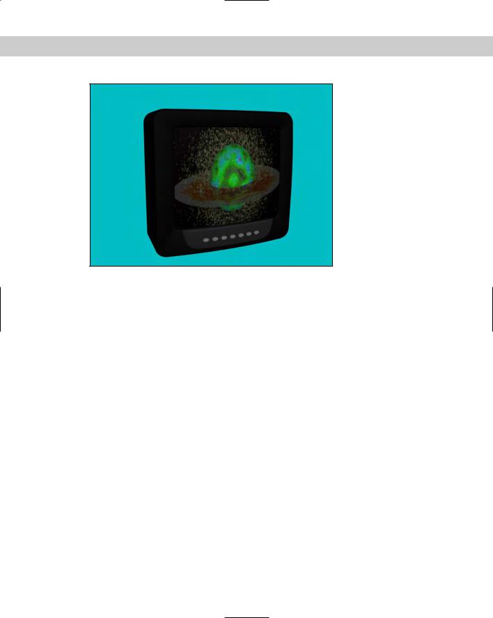
Figure 30-15: You can use IFL files to animate materials via a list of images.
Working with Previews
More than likely, your final output will be rendered using the highest quality settings with all effects enabled, and you can count on this taking a fair amount of time. After waiting several days for a sequence to render is a terrible time to find out that your animation keys are off.
Even viewing animation sequences in the viewports with the Play Animation button cannot catch all problems.
One way to catch potential problems is to create a sample preview animation. Previews are test animation sequences that render quickly to give you an idea of the final output. The Animation menu includes several commands for creating, renaming, and viewing previews. The rendering options available for previews are the same as the shading options that are available in the viewports.
Creating previews
You create previews by choosing Animation Make Preview to open the Make Preview dialog box, shown in Figure 30-16.
In the Make Preview dialog box, you can specify what frames to include using the Active Time Segment or Custom Range options. You can also choose Every Nth Frame or select a specific frame rate in the Playback FPS field. The image size is determined by the Percent of Output value, which is a percentage of the final output size. The resolution is also displayed.

Chapter 30 Animation Basics 753
Figure 30-16: The Make Preview dialog box lets you specify the range, size, and output of a preview file.
The Display in Preview section offers a variety of options to include in the preview. These options include Geometry, Shapes, Lights, Cameras, Helpers, Space Warps, Particle Systems, Active Grid, Safe Frames, Frame Numbers, Background, and Bone Objects. Because the preview output is rendered like the viewports, certain selected objects such as Lights and Cameras actually display their icons as part of the file. The Frame Numbers option prints the frame number in the upper-left corner of each frame.
The Rendering Level drop-down list includes the same shading options used to display objects in the viewports, including Smooth, Smooth + Highlights, Facets, Facets + Highlights, Lit Wireframes, Wireframe, and Bounding Box.
Output options include the default AVI option; a Custom File Type option, which enables you to choose your own format; and the Use Device option, which you can use to render the preview to a different device. For the AVI option, you can select a CODEC, which is used to compress the resulting file. Options include Cinepak Code by Radius, Microsoft Video 1, and Full Frames (uncompressed), depending on the CODECs that are installed on your system. When the Use Device option is selected, the Choose Device button becomes active. Clicking this button opens the Select Output Image Device dialog box, where you can select and configure output devices such as a Digital Recorder.
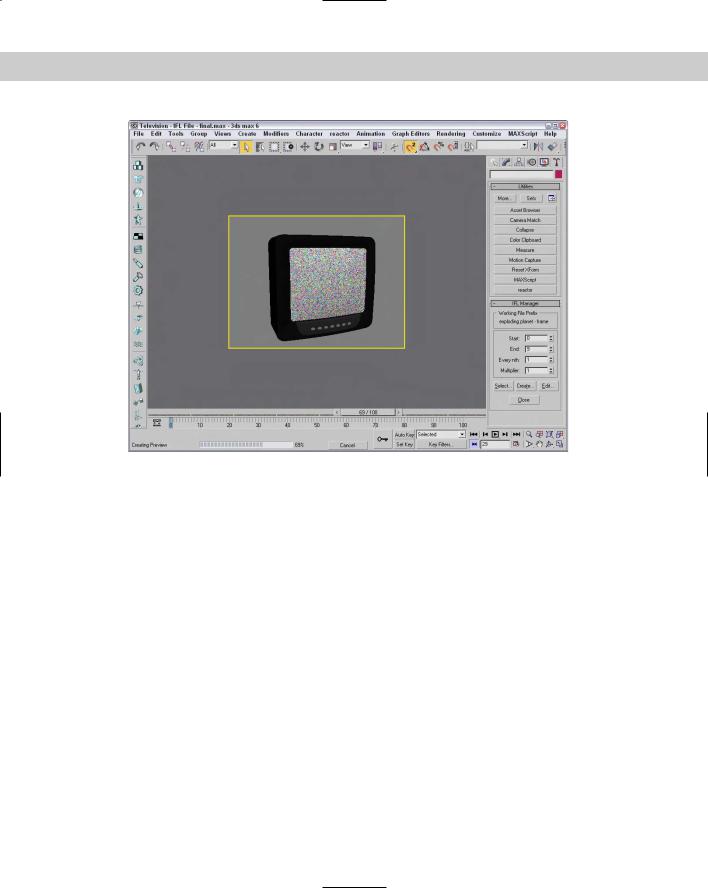
At the bottom of the dialog box is a Render Viewport drop-down list, where you can select which viewport to use to create your preview file. The Create button starts the rendering process. When a preview is being rendered, the viewports are replaced with a single image of the current render frame, and the Status bar is replaced by a Progress bar and a Cancel button. Figure 30-17 shows a preview file being created.
Tip |
You can use the Esc key on your keyboard to cancel a rendering job. |
If you cancel the rendering, the Make Preview alert box offers the options Stop and Play, Stop and Don’t Play, and Don’t Stop.
754 Part VII Animation
Figure 30-17: When a preview file is being created, the viewports are replaced with a single view of the current frame.
Viewing previews
When a preview file is finished rendering, the default Media Player for your system loads and displays the preview file. You can disable this autoplay feature using the Autoplay Preview File option in the General panel of the Preference Settings dialog box.
At any time, you can replay the preview file using the Animation View Preview menu command. This command loads the latest preview file and displays it in the Media Player.
Renaming previews
The preview file is actually saved as a file named scene.avi and is saved by default in the previews subdirectory. Be aware that this file is automatically overwritten when a new preview is created. You can save a preview file by renaming it by choosing Animation Rename Preview File. This command opens the Save Preview As dialog box, where you can give the preview file a name.
Wiring Parameters
Another useful way to expand the number of parameters is to create custom parameters. These custom parameters can define some aspect of the scene that makes sense to you. For example, if you create a model of a bicycle, you can define a custom parameter for the pedal rotation.
Chapter 30 Animation Basics 755
These custom parameters can then be wired to other objects using the Wiring Parameters feature. By wiring parameters, you can make the parameter of one object control the parameter of another object. For example, you can wire the On/Off parameter of a light to the movement of a switch. All parameters that can be animated can be wired.
Adding custom parameters
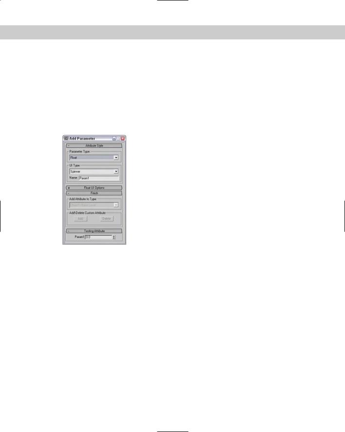
As if the standard parameters for the various modeling types weren’t enough, you can also add your own custom parameters using the Add Parameter panel, shown in Figure 30-18. You can open this modeless panel by choosing Animation Add Custom Attributes.
Figure 30-18: You can use the Add Parameter dialog box to create custom parameters.
The Parameter Type drop-down list lets you choose the parameter format. Possibilities include float (a decimal-point number), integer, Boolean (true or false), array, node, color, and texture map. The UI Type drop-down list defines how the parameter is displayed in the rollout. How the parameter looks depends on the type of parameter. Float and integer values can be spinners or sliders, Boolean values can be check boxes or radio buttons, array values are drop-down lists, nodes are pick buttons (allowing you to select an object in the viewports), color and RGB values are color pickers, and texture maps are map buttons. You can also name the parameter.
The Options rollout changes depending on which parameter type was selected. These rollouts contain settings for the interface’s Width, value ranges, default values, Alignment (left, right, or center), and list items.
The Finish rollout is used to tell which rollout to add the custom attribute to. From the Add Attribute to Type drop-down list, you can choose to add the attribute to the object’s base level, to the selected modifier, or to the object material. The Add and Delete buttons can make the custom parameter appear or disappear in the rollout that you specified. The Testing Attribute rollout shows what the interface element will look like.
The value of custom attributes becomes apparent when you start wiring parameters.
756 Part VII Animation
Using the Parameter Wiring dialog box
You can access the Parameter Wiring dialog box in several places. The Animation Wire Parameters Wire Parameters menu makes a pop-up menu of parameters appear. Selecting a parameter from the menu changes the cursor to a dotted line (like the one used when linking objects). Click the object that you want to wire to, and another pop-up menu lets you choose the parameter to wire to. The Parameter Wiring dialog box appears with the parameter for each object selected from a hierarchy tree.
You can also wire parameters using the right-click quadmenu and selecting Wire Parameters. The Wire Parameters option is disabled if multiple objects are selected.
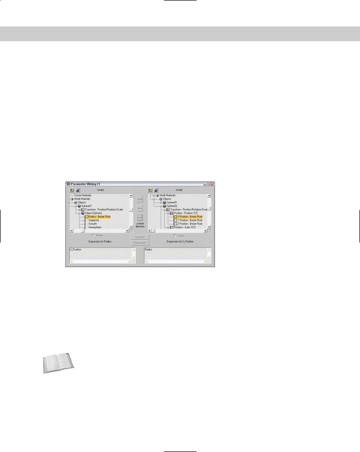
The Parameter Wiring dialog box, shown in Figure 30-19, displays two tree lists containing all the available parameters. This tree list looks very similar to the Track View and lets you connect parameters in either direction or to each other. If you used the Wire Parameters feature to open the Parameter Wiring dialog box, then the parameter for each object is already selected and highlighted in yellow.
Figure 30-19: The Parameter Wiring dialog box can work with expressions.
The three arrow buttons between the two tree lists let you specify the connection direction. These buttons connect the parameter in one pane to the selected parameter in the opposite pane. The direction determines whether the parameter in the left pane controls the parameter in the right pane, or vice versa. You can also select the top bidirectional button to make the parameters mutually affect each other. Below each tree list is a text area where you can enter an expression. An expression is a mathematical statement that follows a specific syntax for defining how one parameter controls the other. These expressions can be any valid expression that is accepted in the Animation Controller dialog box or in MAXScript.
Cross- |
You can learn more about creating and using expressions in Chapter 32, “Using the |
Reference |
Expression Controller.” |
|
After an expression is entered, click the Connect button to complete the wiring. Based on the connection direction, the Master radio button indicates which object controls the other. You can also use this dialog box to disconnect existing wired parameters. You can use the two icon buttons at the top of the dialog box, shown in Table 30-4, to Show All Tracks and to find the next wired parameter.
Chapter 30 Animation Basics 757
Table 30-4: Parameter Wiring Dialog Box Icons
Button Description
Show All Tracks
Next Wired Parameter
After the wiring is completed, the Parameter Wiring dialog box remains open. You can try out the wiring by moving the master object. If the results aren’t what you wanted, you can edit the expression and click the Update button (the Connect button changes to an Update button).
If the expression contains an error, the track title is displayed in red and an error dialog box appears, telling you what the error is. You need to correct the error and click the Update button before the wiring will be in effect. If the wiring is successful, then the track title is displayed in green.
Manipulator helpers
To create general-use controls that can be wired to control various properties, Max includes three Manipulator Helpers. These helpers are Cone Angle, Plane Angle, and Slider. They are available as a subcategory under the Helpers category of the Create panel or in the Create Helpers Manipulators menu.
For the Cone Angle helper, you can set the Angle, Distance, and Aspect settings. The default cone is a circle, but you can make it a square. The Plane Angle helper includes settings for Angle, Distance, and Size.
You can name the Slider helper. This name appears in the viewports above the slider object. You can also set a default value along with maximum and minimum values. To position the object, you can set the X Position, Y Position, and Width settings. You can also set a snap value for the slider.
Once created, you can use these manipulator helpers when the Select and Manipulate button on the main toolbar is enabled (this button must be disabled before the manipulator helpers can be created). The advantage of these helpers is in wiring parameters to be controlled using the helpers.
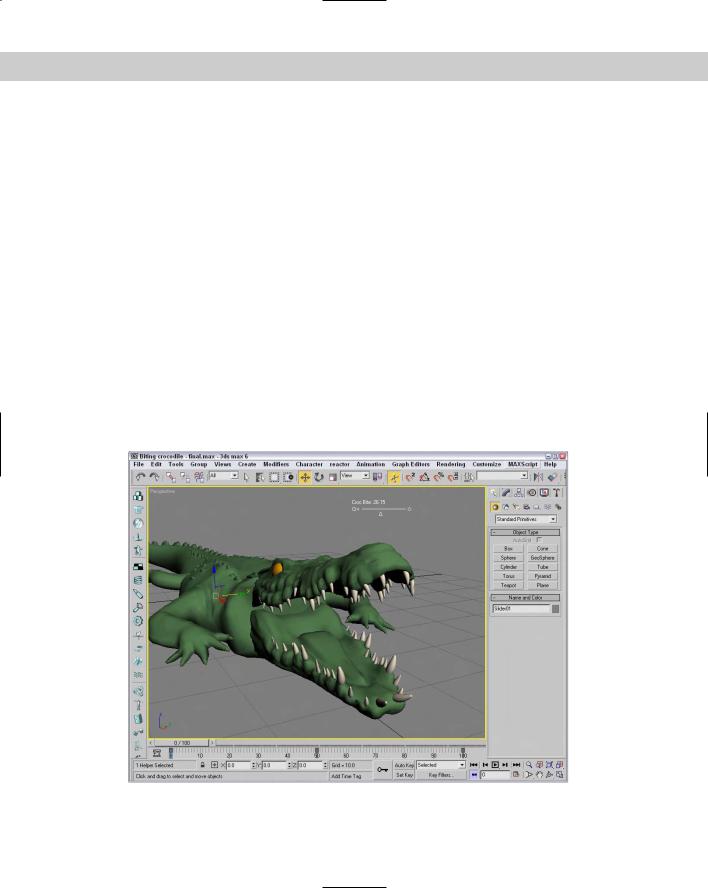
Tutorial: Controlling a crocodile’s bite
One way to use manipulator helpers and wired parameters is to control within limits certain parameters that can be animated. This gives your animation team controls they can use to quickly build animation sequences. In this example, you use a slider to control a crocodile’s jaw movement.
758 Part VII Animation
To create a slider to control a crocodile’s bite, follow these steps:
1.Open the Biting crocodile.max file from the Chap 30 directory on the CD-ROM.
This file includes a crocodile model created by Viewpoint Datalabs. For this model, the head, eyes, and upper teeth have been joined into a single object, and the pivot point for this object has been moved to where the jaw hinges.
2.Select Create Helpers Manipulators Slider and drag in the Perspective view above the crocodile. Name the slider Croc Bite, and set the Maximum value to 60.
3.With the Slider selected, choose Animation Wire Parameter Wire Parameter to access the pop-up menu. Choose Object (Slider) value option, drag the dotted line to the crocodile’s head object, and click. Choose Transform Rotation.
The Parameter Wiring dialog box appears.
4.In the Parameter Wiring dialog box, click the direction arrow that points from the Slider to the head. In the expression text area under the head object, enter the expression angleaxis value [0,1,0] and click the Connect button.
5.Click the Select and Manipulate button on the main toolbar, and drag the slider to the right.
The crocodile’s mouth opens.
Figure 30-20 shows the crocodile biting using the slider control.
Figure 30-20: A slider control is wired to open the crocodile’s mouth.