

- •Preface
- •About This Book
- •Acknowledgments
- •Contents at a Glance
- •Contents
- •Relaxing at the Beach
- •Dressing the Scene
- •Animating Motion
- •Rendering the Final Animation
- •Summary
- •The Interface Elements
- •Using the Menus
- •Using the Toolbars
- •Using the Viewports
- •Using the Command Panel
- •Using the Lower Interface Bar Controls
- •Interacting with the Interface
- •Getting Help
- •Summary
- •Understanding 3D Space
- •Using the Viewport Navigation Controls
- •Configuring the Viewports
- •Working with Viewport Backgrounds
- •Summary
- •Working with Max Scene Files
- •Setting File Preferences
- •Importing and Exporting
- •Referencing External Objects
- •Using the File Utilities
- •Accessing File Information
- •Summary
- •Customizing Modify and Utility Panel Buttons
- •Working with Custom Interfaces
- •Configuring Paths
- •Selecting System Units
- •Setting Preferences
- •Summary
- •Creating Primitive Objects
- •Exploring the Primitive Object Types
- •Summary
- •Selecting Objects
- •Setting Object Properties
- •Hiding and Freezing Objects
- •Using Layers
- •Summary
- •Cloning Objects
- •Understanding Cloning Options
- •Mirroring Objects
- •Cloning over Time
- •Spacing Cloned Objects
- •Creating Arrays of Objects
- •Summary
- •Working with Groups
- •Building Assemblies
- •Building Links between Objects
- •Displaying Links and Hierarchies
- •Working with Linked Objects
- •Summary
- •Using the Schematic View Window
- •Working with Hierarchies
- •Setting Schematic View Preferences
- •Using List Views
- •Summary
- •Working with the Transformation Tools
- •Using Pivot Points
- •Using the Align Commands
- •Using Grids
- •Using Snap Options
- •Summary
- •Exploring the Modifier Stack
- •Exploring Modifier Types
- •Summary
- •Exploring the Modeling Types
- •Working with Subobjects
- •Modeling Helpers
- •Summary
- •Drawing in 2D
- •Editing Splines
- •Using Spline Modifiers
- •Summary
- •Creating Editable Mesh and Poly Objects
- •Editing Mesh Objects
- •Editing Poly Objects
- •Using Mesh Editing Modifiers
- •Summary
- •Introducing Patch Grids
- •Editing Patches
- •Using Modifiers on Patch Objects
- •Summary
- •Creating NURBS Curves and Surfaces
- •Editing NURBS
- •Working with NURBS
- •Summary
- •Morphing Objects
- •Creating Conform Objects
- •Creating a ShapeMerge Object
- •Creating a Terrain Object
- •Using the Mesher Object
- •Working with BlobMesh Objects
- •Creating a Scatter Object
- •Creating Connect Objects
- •Modeling with Boolean Objects
- •Creating a Loft Object
- •Summary
- •Understanding the Various Particle Systems
- •Creating a Particle System
- •Using the Spray and Snow Particle Systems
- •Using the Super Spray Particle System
- •Using the Blizzard Particle System
- •Using the PArray Particle System
- •Using the PCloud Particle System
- •Using Particle System Maps
- •Controlling Particles with Particle Flow
- •Summary
- •Understanding Material Properties
- •Working with the Material Editor
- •Using the Material/Map Browser
- •Using the Material/Map Navigator
- •Summary
- •Using the Standard Material
- •Using Shading Types
- •Accessing Other Parameters
- •Using External Tools
- •Summary
- •Using Compound Materials
- •Using Raytrace Materials
- •Using the Matte/Shadow Material
- •Using the DirectX 9 Shader
- •Applying Multiple Materials
- •Material Modifiers
- •Summary
- •Understanding Maps
- •Understanding Material Map Types
- •Using the Maps Rollout
- •Using the Map Path Utility
- •Using Map Instances
- •Summary
- •Mapping Modifiers
- •Using the Unwrap UVW modifier
- •Summary
- •Working with Cameras
- •Setting Camera Parameters
- •Summary
- •Using the Camera Tracker Utility
- •Summary
- •Using Multi-Pass Cameras
- •Creating Multi-Pass Camera Effects
- •Summary
- •Understanding the Basics of Lighting
- •Getting to Know the Light Types
- •Creating and Positioning Light Objects
- •Viewing a Scene from a Light
- •Altering Light Parameters
- •Working with Photometric Lights
- •Using the Sunlight and Daylight Systems
- •Using Volume Lights
- •Summary
- •Selecting Advanced Lighting
- •Using Local Advanced Lighting Settings
- •Tutorial: Excluding objects from light tracing
- •Summary
- •Understanding Radiosity
- •Using Local and Global Advanced Lighting Settings
- •Working with Advanced Lighting Materials
- •Using Lighting Analysis
- •Summary
- •Using the Time Controls
- •Working with Keys
- •Using the Track Bar
- •Viewing and Editing Key Values
- •Using the Motion Panel
- •Using Ghosting
- •Animating Objects
- •Working with Previews
- •Wiring Parameters
- •Animation Modifiers
- •Summary
- •Understanding Controller Types
- •Assigning Controllers
- •Setting Default Controllers
- •Examining the Various Controllers
- •Summary
- •Working with Expressions in Spinners
- •Understanding the Expression Controller Interface
- •Understanding Expression Elements
- •Using Expression Controllers
- •Summary
- •Learning the Track View Interface
- •Working with Keys
- •Editing Time
- •Editing Curves
- •Filtering Tracks
- •Working with Controllers
- •Synchronizing to a Sound Track
- •Summary
- •Understanding Your Character
- •Building Bodies
- •Summary
- •Building a Bones System
- •Using the Bone Tools
- •Using the Skin Modifier
- •Summary
- •Creating Characters
- •Working with Characters
- •Using Character Animation Techniques
- •Summary
- •Forward versus Inverse Kinematics
- •Creating an Inverse Kinematics System
- •Using the Various Inverse Kinematics Methods
- •Summary
- •Creating and Binding Space Warps
- •Understanding Space Warp Types
- •Combining Particle Systems with Space Warps
- •Summary
- •Understanding Dynamics
- •Using Dynamic Objects
- •Defining Dynamic Material Properties
- •Using Dynamic Space Warps
- •Using the Dynamics Utility
- •Using the Flex Modifier
- •Summary
- •Using reactor
- •Using reactor Collections
- •Creating reactor Objects
- •Calculating and Previewing a Simulation
- •Constraining Objects
- •reactor Troubleshooting
- •Summary
- •Understanding the Max Renderers
- •Previewing with ActiveShade
- •Render Parameters
- •Rendering Preferences
- •Creating VUE Files
- •Using the Rendered Frame Window
- •Using the RAM Player
- •Reviewing the Render Types
- •Using Command-Line Rendering
- •Creating Panoramic Images
- •Getting Printer Help
- •Creating an Environment
- •Summary
- •Creating Atmospheric Effects
- •Using the Fire Effect
- •Using the Fog Effect
- •Summary
- •Using Render Elements
- •Adding Render Effects
- •Creating Lens Effects
- •Using Other Render Effects
- •Summary
- •Using Raytrace Materials
- •Using a Raytrace Map
- •Enabling mental ray
- •Summary
- •Understanding Network Rendering
- •Network Requirements
- •Setting up a Network Rendering System
- •Starting the Network Rendering System
- •Configuring the Network Manager and Servers
- •Logging Errors
- •Using the Monitor
- •Setting up Batch Rendering
- •Summary
- •Compositing with Photoshop
- •Video Editing with Premiere
- •Video Compositing with After Effects
- •Introducing Combustion
- •Using Other Compositing Solutions
- •Summary
- •Completing Post-Production with the Video Post Interface
- •Working with Sequences
- •Adding and Editing Events
- •Working with Ranges
- •Working with Lens Effects Filters
- •Summary
- •What Is MAXScript?
- •MAXScript Tools
- •Setting MAXScript Preferences
- •Types of Scripts
- •Writing Your Own MAXScripts
- •Learning the Visual MAXScript Editor Interface
- •Laying Out a Rollout
- •Summary
- •Working with Plug-Ins
- •Locating Plug-Ins
- •Summary
- •Low-Res Modeling
- •Using Channels
- •Using Vertex Colors
- •Rendering to a Texture
- •Summary
- •Max and Architecture
- •Using AEC Objects
- •Using Architectural materials
- •Summary
- •Tutorial: Creating Icy Geometry with BlobMesh
- •Tutorial: Using Caustic Photons to Create a Disco Ball
- •Summary
- •mental ray Rendering System
- •Particle Flow
- •reactor 2.0
- •Schematic View
- •BlobMesh
- •Spline and Patch Features
- •Import and Export
- •Shell Modifier
- •Vertex Paint and Channel Info
- •Architectural Primitives and Materials
- •Minor Improvements
- •Choosing an Operating System
- •Hardware Requirements
- •Installing 3ds max 6
- •Authorizing the Software
- •Setting the Display Driver
- •Updating Max
- •Moving Max to Another Computer
- •Using Keyboard Shortcuts
- •Using the Hotkey Map
- •Main Interface Shortcuts
- •Dialog Box Shortcuts
- •Miscellaneous Shortcuts
- •System Requirements
- •Using the CDs with Windows
- •What’s on the CDs
- •Troubleshooting
- •Index
1166 Part XIII Max in Action
Select by Channel modifier
After new channels have been created, you can recall them at any time using the Select by Channel modifier. This modifier is found in the Create Selection Modifiers Select by Channel menu command. Using this modifier, you can choose to Replace, Add, or Subtract a given channel from the selection. The available channels for the selection are listed by their channel name in a drop-down list.
Using Vertex Colors
When creating models that are for games, the size of the texture map can be prohibitive. I mean, what model that weighs in at 16 kilobytes or less wants to carry around a 2-megabyte texture map? The solution that much of the gaming world relies on is to apply a single color to a vertex. Having each vertex remember its color (or even several colors) requires very little additional information for the mesh and can create some good shading. Colors are then interpolated across the face of the polygon between two different colors on adjacent vertices.
The results aren’t as clean and detailed as a texture map, but for their size, vertex colors are worth the price.
Assigning vertex colors
Vertex colors can be assigned in the Surface Properties rollout for Editable Mesh and Editable Patch objects, and in the Vertex Properties rollout for Editable Poly objects. They also can be assigned in Face, Polygon, and Element subobject modes using a little rollout section called Edit Vertex Colors. Within this section are two color swatches for selecting a Color and Illumination values. The Alpha value sets the alpha transparency value for the vertex.
Painting vertices with the Vertex Paint modifier
Another, more interactive way to color vertices is with the Vertex Paint modifier. This modifier lets you paint on an object by specifying a color for each vertex. If adjacent vertices have different colors assigned, then a gradient is created across the face. The benefit of this coloring option is that it is very efficient and requires almost no memory.
New |
The Vertex Paint modifier has been enhanced for 3ds max 6. |
Feature |
|
The Vertex Paint modifier lets you specify a color and paint directly on the surface of an object by painting the vertices. The color is applied with a paintbrush-shaped cursor. The modifier can be applied multiple times to an object, giving you the ability to blend several layers of vertex paints together. You can find this modifier in the Modifiers Mesh Editing submenu.
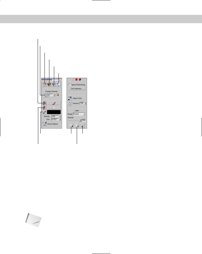
Applying this modifier opens a VertexPaint dialog box called the Paintbox, shown in Figure 50-5. At the top of the Paintbox are four icons that can be used to show the visible results of the painting in the viewports. The options include Vertex Color Display–Unshaded, Vertex Color Display–Shaded, Disable Vertex Color Display, and Toggle Texture Display–On/Off.
Chapter 50 Max and Games 1167
Paint All
Vertex Color
Vertex Color Display – unshaped
Vertex Color Display – shaped
Disabled Vertex Color Display
Toggle Texture Display On/Off
Pick color |
New |
Condense to a |
from object |
Layer |
Single Layer |
Erase All |
Delete Layer |
|
Figure 50-5: The Paintbox palette for the Vertex Paint modifier includes a wealth of features.
The Vertex Color icon flyout lets you work on the Vertex Color, Illumination, Alpha, or any one of the 99 available map channels. The lock icon locks the display to the selected channel, or you could be looking at a different channel than the one you are painting.
The large Paint and Erase buttons let you add or remove vertex colors using the color specified in the color swatch. You can also select colors from objects in the viewports using the eyedropper tool, and then set the Opacity.
The Size value determines the size of the brush used to paint. Max supports pressure-sensi- tive devices such as a graphics tablet, and you can set the brush options using the Brush Options dialog box, shown in Figure 50-6. When paining on the surface of an object, a blue normal line appears. This line guides you as you paint so that you know you’re on the correct surface.
Note The Brush Options dialog box is the same dialog box that is used to paint weights for the Skin modifier, which is discussed in Chapter 35, “Rigging Characters.”

1168 Part XIII Max in Action
Figure 50-6: The Brush Options dialog box lets you define the profile curve used to paint vertex colors.
The Paintbox also includes three subobject selection icons. These icons can be used to select certain Vertices, Faces, or Elements to be painted. This limits the painting to the selected subobjects only. You can also select to Ignore Backfacing and use Soft Selection.
The Adjust Color dialog box lets you change all the painted colors applied to an object using HSV or RGB color sliders. The Preview option makes the color adjustment visible in the viewports if selected. Below the Adjust Color icon is the Blur Selected icon that blurs together all the vertex colors based on the designated Amount value.
Colors can be mixed between layers using the various blending modes. Clicking the New Layer button adds a new instance of the Vertex Paint modifier to the Modifier Stack; the Delete Layer button does the opposite. Click the Condense to a Single Layer button to merge all the consecutive Vertex Paint modifiers to a single instance using the selected blending mode.
Note Any files that are opened within 3ds max 6 that have an older version of the Vertex Paint modifier are displayed as OldVertexPaint in the Modifier Stack.
Tutorial: Marking heart tension
As an example of using the Vertex Paint modifier, imagine a doctor who has a 3D model of the human heart. While discussing the results of the latest test with a patient, the doctor can color parts of the heart model to illustrate the various points.
To color on a human heart using the Vertex Paint modifier, follow these steps:
1.Open the Vertex paint on heart.max file from the Chap 50 directory on the CD-ROM. This file includes a heart mesh created by Viewpoint Datalabs.
2.Select a portion of the heart model, and choose Modifiers Mesh Editing Vertex Paint to apply the Vertex Paint modifier.
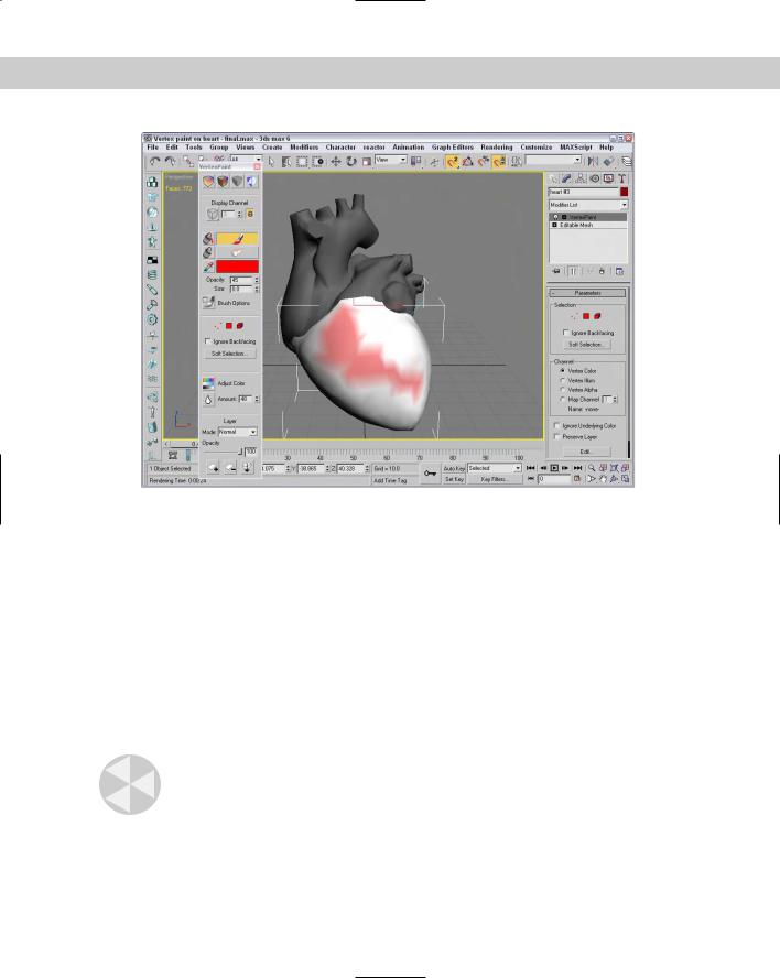
3.In the Paintbox that opens, select the red color and then click the Paint button. Then drag the mouse over the surface of the Perspective view.
Figure 50-7 shows the resulting color.
Chapter 50 Max and Games 1169
Figure 50-7: The Vertex Paint modifier can apply color to an object by assigning a color to its vertices.
The Assign Vertex Color utility
The Assign Vertex Color utility works a little differently. It converts any existing material colors to vertex colors. To use this utility, select an object, choose a Channel, choose a Light Model (either Lighting, Shaded, or Diffuse), and click the Assign to Selected button.
Rendering to a Texture
When working with a game engine, game designers are always looking for ways to increase the speed and detail of objects in the game. One common way to speed game calculations is to pre-render the textures used in a game and then to save these textures as a texture map. The texture map takes more memory to save, but can greatly speed the rendering time required by the game engine. This process of pre-rendering a texture is called texture baking.
Caution |
If you bake a texture into an object and then render it with the rest of the scene, the object |
|
gets a double dose of light. |
1170 Part XIII Max in Action
Texture baking can be accomplished in Max using the Rendering Render to Texture menu command (or by pressing the 0 key). This opens the Render to Textures dialog box. In several ways, the Render to Textures dialog box resembles the Render Scene dialog box, including a Render button at the bottom edge of the interface. The interface also includes an Unwrap Only button. This button can be used to flatten the UVW Coordinates for the selected objects and to automatically create a map channel.
New |
The Render to Textures dialog box has been enhanced in 3ds max 6. |
Feature |
|
General Settings and Baking Objects
If the Automatic Unwrap Mapping option in the General Settings rollout, shown in Figure 50-8, is enabled, then the object to be baked has the Unwrap UVW modifier applied using the Flatten mapping type. For this type, you can set the Threshold Angle (which is the difference between the normals of adjacent faces; if the angular value is greater than the Threshold Angle value, then a hard edge is created between the faces), the Spacing (which is the amount of space between different map pieces), and whether map pieces can be rotated and used to fill in holes of larger map pieces. The Clear Unwrappers option removes any previous Unwrap UVW modifiers from the object.
Figure 50-8: The General Settings rollout of the Render to Textures panel includes settings for all objects.
For the render pass, you can use the Production or Draft render settings, or you can select and use a Rendering Preset. The Setup button opens the Render Scene panel, where you can change the render settings.
In the Objects to Bake rollout, you can select exactly which channels are included in the rendered texture. You can select to bake an Individual object, All Selected Objects, or All Prepared Objects, which are all objects with at least one texture element. Texture elements are added using this rollout.
Chapter 50 Max and Games 1171
Output Settings
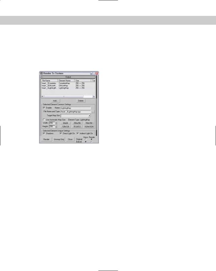
The Output rollout, shown in Figure 50-9, can be different for different selections. The Enable option can disable the settings for the selected object. By default, unwrap mapping uses channel 3, but you can change this channel if you wish. If a different mapping uses channel 3 and you don’t change this, the new mapping replaces the old one. The Edge Padding defines the overlap in pixels of the texture.
Figure 50-9: The Output rollout of the Render to Textures panel includes settings for specific objects.
Clicking the Add button lets you select the type of texture maps that you can render. You will want to use different maps depending on the purpose of the map, and you may want to render several at a time. The available types are CompleteMap, SpecularMap, DiffuseMap, ShadowsMap, LightingMap, NormalsMap, BlendMap, and AlphaMap. Elements that are added to the list can be disabled using the check boxes to the left. You can also change the map size or use the Automatic Map Size option, which bases the map size on the object size. Some map elements present a list of components to include in the map. These components appear in another rollout.
The size of the texture map depends on the size of the object, but you can set a Scale value for greater resolution and set Min and Max values to keep the maps within reason. By default, maps are saved to the /images directory, but you can select a different directory if you prefer.
The Clear Shell Materials button removes the Shell materials for the baked objects and restores their original materials.
1172 Part XIII Max in Action
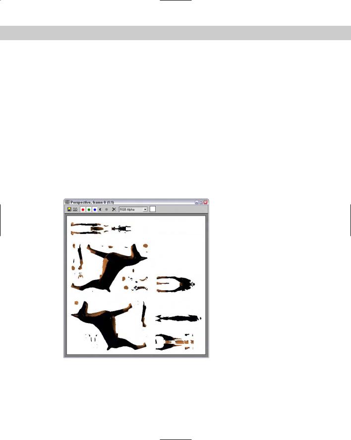
Tutorial: Baking the textures for a dog model
To practice baking textures, we bake a complete map of just the dog’s head. Now I need to find a game engine to run it in.
To bake a dog’s head texture, follow these steps:
1.Open the Doberman.max file from the Chap 50 directory on the CD-ROM. This file includes a dog model created by Viewpoint Datalabs.
2.Select Rendering Render to Texture (or press the 0 key) to open the Render to Textures panel.
3.Select the dog’s body object. In the Render to Textures panel, set the Threshold Angle to 75, and make sure that the Rendered Frame Window option is set. In the Output roll-
out, click the Add button and double-click the CompleteMap option. Set the Map Size to 512×512, and click the Render button.
Figure 50-10 shows the resulting texture map. If you look in the Modify panel, you’ll see that Automatic Flatten UVs modifier has been applied to the object. If you look at the material applied to the object, you’ll see that it consists of a Shell material.
Figure 50-10: A texture map created with the Render to Textures panel