

- •Preface
- •About This Book
- •Acknowledgments
- •Contents at a Glance
- •Contents
- •Relaxing at the Beach
- •Dressing the Scene
- •Animating Motion
- •Rendering the Final Animation
- •Summary
- •The Interface Elements
- •Using the Menus
- •Using the Toolbars
- •Using the Viewports
- •Using the Command Panel
- •Using the Lower Interface Bar Controls
- •Interacting with the Interface
- •Getting Help
- •Summary
- •Understanding 3D Space
- •Using the Viewport Navigation Controls
- •Configuring the Viewports
- •Working with Viewport Backgrounds
- •Summary
- •Working with Max Scene Files
- •Setting File Preferences
- •Importing and Exporting
- •Referencing External Objects
- •Using the File Utilities
- •Accessing File Information
- •Summary
- •Customizing Modify and Utility Panel Buttons
- •Working with Custom Interfaces
- •Configuring Paths
- •Selecting System Units
- •Setting Preferences
- •Summary
- •Creating Primitive Objects
- •Exploring the Primitive Object Types
- •Summary
- •Selecting Objects
- •Setting Object Properties
- •Hiding and Freezing Objects
- •Using Layers
- •Summary
- •Cloning Objects
- •Understanding Cloning Options
- •Mirroring Objects
- •Cloning over Time
- •Spacing Cloned Objects
- •Creating Arrays of Objects
- •Summary
- •Working with Groups
- •Building Assemblies
- •Building Links between Objects
- •Displaying Links and Hierarchies
- •Working with Linked Objects
- •Summary
- •Using the Schematic View Window
- •Working with Hierarchies
- •Setting Schematic View Preferences
- •Using List Views
- •Summary
- •Working with the Transformation Tools
- •Using Pivot Points
- •Using the Align Commands
- •Using Grids
- •Using Snap Options
- •Summary
- •Exploring the Modifier Stack
- •Exploring Modifier Types
- •Summary
- •Exploring the Modeling Types
- •Working with Subobjects
- •Modeling Helpers
- •Summary
- •Drawing in 2D
- •Editing Splines
- •Using Spline Modifiers
- •Summary
- •Creating Editable Mesh and Poly Objects
- •Editing Mesh Objects
- •Editing Poly Objects
- •Using Mesh Editing Modifiers
- •Summary
- •Introducing Patch Grids
- •Editing Patches
- •Using Modifiers on Patch Objects
- •Summary
- •Creating NURBS Curves and Surfaces
- •Editing NURBS
- •Working with NURBS
- •Summary
- •Morphing Objects
- •Creating Conform Objects
- •Creating a ShapeMerge Object
- •Creating a Terrain Object
- •Using the Mesher Object
- •Working with BlobMesh Objects
- •Creating a Scatter Object
- •Creating Connect Objects
- •Modeling with Boolean Objects
- •Creating a Loft Object
- •Summary
- •Understanding the Various Particle Systems
- •Creating a Particle System
- •Using the Spray and Snow Particle Systems
- •Using the Super Spray Particle System
- •Using the Blizzard Particle System
- •Using the PArray Particle System
- •Using the PCloud Particle System
- •Using Particle System Maps
- •Controlling Particles with Particle Flow
- •Summary
- •Understanding Material Properties
- •Working with the Material Editor
- •Using the Material/Map Browser
- •Using the Material/Map Navigator
- •Summary
- •Using the Standard Material
- •Using Shading Types
- •Accessing Other Parameters
- •Using External Tools
- •Summary
- •Using Compound Materials
- •Using Raytrace Materials
- •Using the Matte/Shadow Material
- •Using the DirectX 9 Shader
- •Applying Multiple Materials
- •Material Modifiers
- •Summary
- •Understanding Maps
- •Understanding Material Map Types
- •Using the Maps Rollout
- •Using the Map Path Utility
- •Using Map Instances
- •Summary
- •Mapping Modifiers
- •Using the Unwrap UVW modifier
- •Summary
- •Working with Cameras
- •Setting Camera Parameters
- •Summary
- •Using the Camera Tracker Utility
- •Summary
- •Using Multi-Pass Cameras
- •Creating Multi-Pass Camera Effects
- •Summary
- •Understanding the Basics of Lighting
- •Getting to Know the Light Types
- •Creating and Positioning Light Objects
- •Viewing a Scene from a Light
- •Altering Light Parameters
- •Working with Photometric Lights
- •Using the Sunlight and Daylight Systems
- •Using Volume Lights
- •Summary
- •Selecting Advanced Lighting
- •Using Local Advanced Lighting Settings
- •Tutorial: Excluding objects from light tracing
- •Summary
- •Understanding Radiosity
- •Using Local and Global Advanced Lighting Settings
- •Working with Advanced Lighting Materials
- •Using Lighting Analysis
- •Summary
- •Using the Time Controls
- •Working with Keys
- •Using the Track Bar
- •Viewing and Editing Key Values
- •Using the Motion Panel
- •Using Ghosting
- •Animating Objects
- •Working with Previews
- •Wiring Parameters
- •Animation Modifiers
- •Summary
- •Understanding Controller Types
- •Assigning Controllers
- •Setting Default Controllers
- •Examining the Various Controllers
- •Summary
- •Working with Expressions in Spinners
- •Understanding the Expression Controller Interface
- •Understanding Expression Elements
- •Using Expression Controllers
- •Summary
- •Learning the Track View Interface
- •Working with Keys
- •Editing Time
- •Editing Curves
- •Filtering Tracks
- •Working with Controllers
- •Synchronizing to a Sound Track
- •Summary
- •Understanding Your Character
- •Building Bodies
- •Summary
- •Building a Bones System
- •Using the Bone Tools
- •Using the Skin Modifier
- •Summary
- •Creating Characters
- •Working with Characters
- •Using Character Animation Techniques
- •Summary
- •Forward versus Inverse Kinematics
- •Creating an Inverse Kinematics System
- •Using the Various Inverse Kinematics Methods
- •Summary
- •Creating and Binding Space Warps
- •Understanding Space Warp Types
- •Combining Particle Systems with Space Warps
- •Summary
- •Understanding Dynamics
- •Using Dynamic Objects
- •Defining Dynamic Material Properties
- •Using Dynamic Space Warps
- •Using the Dynamics Utility
- •Using the Flex Modifier
- •Summary
- •Using reactor
- •Using reactor Collections
- •Creating reactor Objects
- •Calculating and Previewing a Simulation
- •Constraining Objects
- •reactor Troubleshooting
- •Summary
- •Understanding the Max Renderers
- •Previewing with ActiveShade
- •Render Parameters
- •Rendering Preferences
- •Creating VUE Files
- •Using the Rendered Frame Window
- •Using the RAM Player
- •Reviewing the Render Types
- •Using Command-Line Rendering
- •Creating Panoramic Images
- •Getting Printer Help
- •Creating an Environment
- •Summary
- •Creating Atmospheric Effects
- •Using the Fire Effect
- •Using the Fog Effect
- •Summary
- •Using Render Elements
- •Adding Render Effects
- •Creating Lens Effects
- •Using Other Render Effects
- •Summary
- •Using Raytrace Materials
- •Using a Raytrace Map
- •Enabling mental ray
- •Summary
- •Understanding Network Rendering
- •Network Requirements
- •Setting up a Network Rendering System
- •Starting the Network Rendering System
- •Configuring the Network Manager and Servers
- •Logging Errors
- •Using the Monitor
- •Setting up Batch Rendering
- •Summary
- •Compositing with Photoshop
- •Video Editing with Premiere
- •Video Compositing with After Effects
- •Introducing Combustion
- •Using Other Compositing Solutions
- •Summary
- •Completing Post-Production with the Video Post Interface
- •Working with Sequences
- •Adding and Editing Events
- •Working with Ranges
- •Working with Lens Effects Filters
- •Summary
- •What Is MAXScript?
- •MAXScript Tools
- •Setting MAXScript Preferences
- •Types of Scripts
- •Writing Your Own MAXScripts
- •Learning the Visual MAXScript Editor Interface
- •Laying Out a Rollout
- •Summary
- •Working with Plug-Ins
- •Locating Plug-Ins
- •Summary
- •Low-Res Modeling
- •Using Channels
- •Using Vertex Colors
- •Rendering to a Texture
- •Summary
- •Max and Architecture
- •Using AEC Objects
- •Using Architectural materials
- •Summary
- •Tutorial: Creating Icy Geometry with BlobMesh
- •Tutorial: Using Caustic Photons to Create a Disco Ball
- •Summary
- •mental ray Rendering System
- •Particle Flow
- •reactor 2.0
- •Schematic View
- •BlobMesh
- •Spline and Patch Features
- •Import and Export
- •Shell Modifier
- •Vertex Paint and Channel Info
- •Architectural Primitives and Materials
- •Minor Improvements
- •Choosing an Operating System
- •Hardware Requirements
- •Installing 3ds max 6
- •Authorizing the Software
- •Setting the Display Driver
- •Updating Max
- •Moving Max to Another Computer
- •Using Keyboard Shortcuts
- •Using the Hotkey Map
- •Main Interface Shortcuts
- •Dialog Box Shortcuts
- •Miscellaneous Shortcuts
- •System Requirements
- •Using the CDs with Windows
- •What’s on the CDs
- •Troubleshooting
- •Index
592 Part IV Materials and Maps
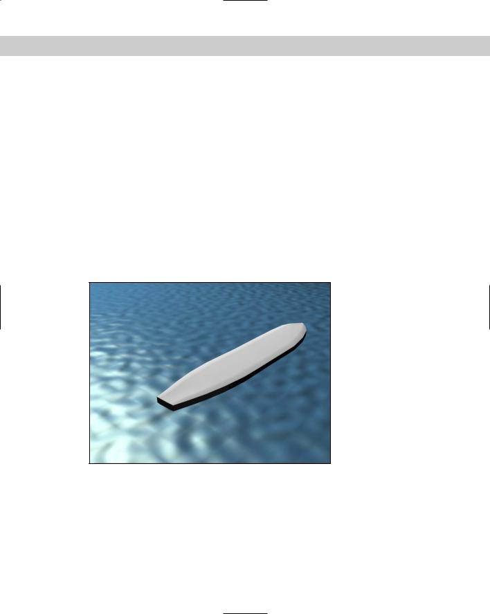
To apply a Top/Bottom compound material to a surfboard, follow these steps:
1.Open the Surfboard.max file from the Chap 21 directory on the CD-ROM.
This file contains a surfboard model and an infinite plane to represent the ocean.
2.Apply the Ocean Surface material, which is already created in the Material Editor, to the plane object by dragging the material from the Material Editor to the Plane object.
3.In the Material Editor, select the second sample slot and click the Type button. From the Material/Map Browser, select the Browse From New option and double-click the Top/Bottom material.
4.When the Replace Material dialog box appears, select the Discard Old Material option. Type the name Surfboard for the new material. Then click the Top Material button, name the material Surfboard Top, and change the Diffuse color to White. In the material drop-down list, select Surfboard and then click the Bottom Material button. Give this material the name Surfboard Bottom, and change the Diffuse color to Black.
5.Click the Material/Map Navigator button to view the hierarchy of the material. Then drag this material to the surfboard object.
Figure 21-5 shows the resulting image.
Figure 21-5: A rendered image of a surfboard with the Top/Bottom compound material applied
Using Raytrace Materials
Raytracing is a rendering method that calculates image colors by following imaginary light rays as they move through a scene. These rays can travel through transparent objects and reflect realistically off shiny materials. The results are stunning realistic images, but the drawback is the amount of time it takes to render using raytrace materials. Scenes with lots of lights and reflecting materials take even longer.
Chapter 21 Creating Advanced Multi-Layer Materials |
593 |
Cross- |
Chapter 44, “Raytracing and mental ray,” covers the raytracing material settings in detail. |
Reference |
|
Using the Matte/Shadow Material
You can apply matte/shadow materials to objects to make portions of the model invisible. This lets any objects behind the object or in the background show through. Objects with matte/shadow materials applied can also cast and receive shadows. The effect of these materials is visible only when the object is rendered.
Matte/Shadow Basic Parameters rollout
You can apply a matte/shadow material by clicking the Type button and selecting Matte/ Shadow from the Material/Map Browser. Matte/shadow materials include only a single rollout: the Matte/Shadow Basic Parameters.
The Opaque Alpha option causes the matte material to appear in an alpha channel. This essentially is a switch for turning Matte objects on and off.
You can apply atmospheric effects such as fog and volume light to Matte materials. The At Background Depth option applies the fog to the background image. The At Object Depth option applies the fog as if the object were rendered.
Cross- |
Find out about Atmospheric effects in Chapter 42, “Using Atmospheric Effects.” |
Reference |
|
The Receive Shadows section enables shadows to be cast on a Matte object. You can also specify the Shadow Brightness and color. Increasing Shadow Brightness values makes the shadow more transparent. The Affect Alpha option makes the shadows part of the alpha channel.
Matte objects can also have Reflections. The Amount spinner controls how much reflection is used, and the Map button opens the Material/Map Browser.
Tutorial: Ballooning in New York
Touring New York City can be exhilarating and exasperating at the same time, but the real way to tour New York City is by balloon (or by virtual balloon). This way, you won’t have to worry about the crowds or bustle, but taking the subway might be a little difficult. In this tutorial, we visit the Statue of Liberty in a balloon and use a Shadow/Matte material to fly the balloon behind the statue.
To use a matte/shadow material to hide geometry, follow these steps:
1.Open the Balloon over the Statue of Liberty.max file from the Chap 21 directory on the CD-ROM.
This file contains a simple balloon mesh and a background image of the Statue of Liberty. I also created in Adobe Photoshop a simple image with four horizontally striped colors to apply as a map to the balloon. Another preparation step was to create a mask for the Statue of Liberty. To do so, I loaded the Statue of Liberty image into a drawing program like Adobe Illustrator and used the Auto-Trace tool to convert the

594 Part IV Materials and Maps
outline of the statue to splines. I saved the traced image as an AI file called Statue of Liberty Mask and imported the AI file into Max, where I created an extruded spline with the same shape as the background statue.
2.Open the Material Editor by pressing the M keyboard shortcut. Select the first sample slot, and name the material Balloon Fabric. Then click the map button to the right of the Diffuse color swatch. In the Material/Map Browser, double-click the Bitmap selection. A File dialog box loads. Locate the image named Balloon Stripes.tif, and click the Open button. After loading the bitmap, enter 75 as the W Angle in the Coordinates rollout to apply the map at an angle. Drag the sample slot to the balloon to apply the map. Use the Show Map in Viewport button to see the applied results.
3.Use the Zoom and Pan tools to align the mask object on top of the background image so it covers the statue.
4.With the mask object in place, open the Material Editor and select the second sample slot. Name the slot Statue of Liberty Matte, and click the Type button. Select the matte/shadow material by double-clicking it. Then apply it to the mask object.
5.Position the balloon in the viewport so it covers the Statue of Liberty in the Perspective view. Make sure that the balloon is behind the mask object.
6.To see the final result, you need to render the image. To do this, select Rendering Render (or press F10) to open the Render Scene dialog box. Click the Render button at the bottom of the dialog box, and the image is rendered in the Rendered Frame Window.
Figure 21-6 shows the resulting rendered image.
Figure 21-6: A rendered balloon object behind an object with a matte/shadow material applied
Chapter 21 Creating Advanced Multi-Layer Materials |
595 |
Using the Ink ‘n’ Paint Material
Although it may seem silly, many different production houses use Max to create 2D linedrawn cartoons. This is accomplished using the Ink ‘n’ Paint material. Traditionally, cartoons have been drawn by hand using a paper and pen. Then animation houses found that, using computers, you can fill in a cartoon feature easily, but using a 3D program like Max with its ability to animate using keyframes simplifies the animation task even further. The difference is in how the objects are rendered; the Ink ‘n’ Paint material controls this.
With the Ink ‘n’ Paint material selected, several rollouts appear, including the Basic Material Extensions. This rollout includes options for making the material 2-Sided, enabling a Face Map, and making the material Faceted. Other options cause the background to be foggy when not painting and make the alpha channel opaque. Maps are available for Bump and Displacement.
Controlling paint and ink
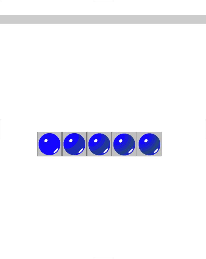
The Paint Controls rollout includes settings for how the paint (or colors inside the ink outline) is applied. You can specify colors for the Lighted, Shaded, and Highlight colors. The Lighted color is used for sections of the material that face the scene lights, the Shaded color is used for sections that are in the shadows, and the Highlight color is for the specular highlights. For each color, you can also select a map with an amount value. The Paint Levels value sets the number of colors that are used to color the material. The Glossiness value determines the size of the highlight. Figure 21-7 shows materials with Paint Level values of 2-6.
Figure 21-7: Use the Paint Level value to set the number of colors used in the material
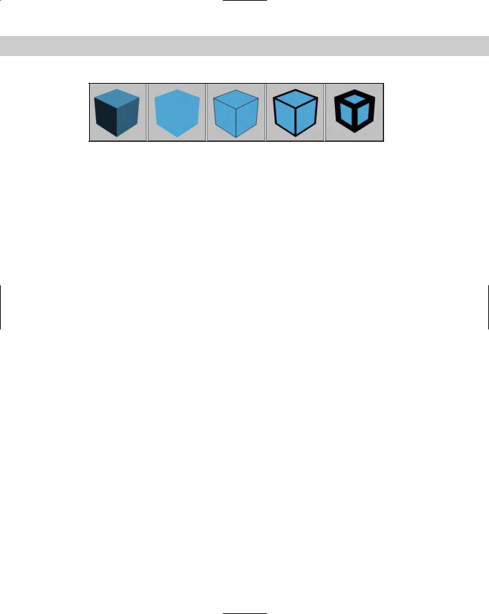
The Ink Controls rollout includes an Ink option that you can use to turn off the outlining ink completely. You can also set the Ink Quality to values between 1 and 3. The higher quality values trace the edges better, but require more time to complete. The width of the ink strokes can be set to Variable Width or a Clamped width. For each option, you can select a Minimum ink width and if Variable Width is enabled, you can choose a Maximum ink width. For the Variable Width option, the stroke changes so that the minimum setting is used in lighted areas and the maximum width is used in shaded areas. This helps to accentuate the lighting. You can also apply the ink width as a map. Figure 21-8 shows the Ink ‘n’ Paint material applied to a cube. The first image shows a standard material; the second image has the Ink option disabled. The last three images have Width values of 1, 10, and 30.
596 Part IV Materials and Maps
Figure 21-8: The Paint Level value sets the number of colors used in the material
The rest of the options in the Ink Controls rollout are enabled to control where the ink is applied to the object. Options include Outline, Overlap, Underlap, Smoothing Group, and Material ID. For each of these options (except for Smoothing Group), you can alter a Bias value that can adjust intersecting edges. Each of these options can be applied as a map.
Tutorial: Cartooning a turtle
As an example of the Ink ‘n’ Paint material, we’ll render a cartoonish turtle model created by Zygote Media as a cartoon that is fit for the Sunday papers.
To apply the Ink ‘n’ Paint material to a turtle model, follow these steps:
1.Open the Cartoon turtle.max file from the Chap 21 directory on the CD-ROM. This file includes a simple turtle model.
2.With the turtle model selected, open the Material Editor by choosing the Rendering Material Editor menu command (or by pressing the M key).
The turtle’s current materials are displayed.
3.In the Utility panel, select the Color Clipboard button, and in the Color Clipboard rollout, click the New Floater button. A palette of colors opens. Drag the Diffuse colors from each current material to the Color Clipboard for each of the five materials.
4.Select the first sample slot, and click on the Material Type button to open the Material/ Map Browser. Double-click the Ink ‘n’ Paint material type from the list. Then drag the corresponding color from the Color Clipboard, and copy it in the Lighted color swatch of the Paint Controls rollout. Repeat this for each of the five materials.
5.Open and render the Perspective viewport using the Render Scene dialog box.
Figure 21-9 shows the resulting cartoon.