

24 |
Part I Learning the Max Interface |
each new version takes us closer to the perfect interface (but I’m still looking for the “read my thoughts” feature). Discreet has built a loophole into the program to cover anyone who complains about the interface — customization. If you don’t like the current interface, you can change it to be exactly what you want.
Cross- |
Customizing the Max interface is covered in Chapter 4, “Customizing the Max Interface and |
Reference |
Setting Preferences.” |
|
This chapter examines the latest incarnation of the Max interface and presents some tips that make the interface feel comfortable, not cumbersome.
Tip If you are an existing user, I’ve made liberal use of the New Feature icon throughout this chapter to highlight what has changed with this edition. If you’re anxious to get to the new stuff, I’d suggest that you quickly scan this chapter looking for the New Feature icons, which refer you to the chapters where the new features are covered.
The Interface Elements
If you’re new to the Max interface, the first order of business is to take a stroll around the block and meet the neighbors. The Max interface has a number of interface elements that neatly group all the similar commands together. For example, all the commands for controlling the viewports are grouped together in the Viewport Navigation Controls found in the lower-right corner of the interface.
Note If all the details of every interface command were covered in this chapter, it would be an awfully long chapter. So I include a simple cross-reference to the chapter where more information can be found about each command.
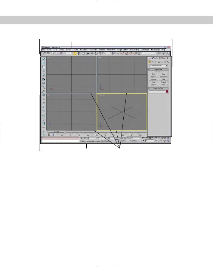
The entire interface can be divided into five easy elements. Each of these interface elements, in turn, has groupings of sub-elements. The five main interface elements are listed here and shown in Figure 1-1:
Menus: This is the default source for most commands, but also one of the most timeconsuming interface elements. The menus are found along the top edge of the Max window.
Toolbars: Max includes several toolbars of icon buttons that provide single-click access to features. These toolbars can float independently or can be docked to an interface edge.
Viewports: Four separate views into the scene show the Top, Front, Left, and Perspective viewpoints.
Command Panel: The major control panel located to the right of the four viewports, it has six tabbed icons at its top that you can click to open the various panels. Each panel includes rollouts containing parameters and settings. These rollouts change depending on the object and tab that is selected.
Lower Interface Bar: Along the bottom edge of the interface window is a collection of miscellaneous controls.
Chapter 1 Finding Your Way — Exploring the Max Interface |
25 |
Main toolbar |
Menus |
Command Panel |
Docked toolbar |
Lower Interface Bar |
Viewports |
Figure 1-1: Max includes five main interface elements.
In addition to these default elements are several additional interface elements that you will find useful. These controls aren’t initially visible when Max is first loaded, but they can be accessed by working with the interface. These additional interface elements include the following:
Floating toolbars: Several toolbars are available as floating toolbars by default, but you can create more if you like. You access them by choosing Customize Show UI Show Floating Toolbars or by selecting them from the toolbar’s right-click pop-up menu.
Quadmenus: Right-clicking on the active viewport makes a pop-up menu with up to four panes appear. This is called a quadmenu. Quadmenus offer context-sensitive commands based on the object or location being clicked.
Dialog boxes and editors: Some commands open a separate window of controls. These dialog boxes may contain their own menus, toolbars, and interface elements. A good example of this element is the Material Editor, which has enough controls to keep you busy for a while.
26 |
Part I Learning the Max Interface |
Using the Menus
The pull-down menus at the top of the Max interface include most of the features available in Max and are a great place for beginners to start. Several of the menu commands have corresponding toolbar buttons and keyboard shortcuts. To execute a menu command, you can choose it from the menu with the mouse cursor, click its corresponding toolbar button if it has one, or press its keyboard shortcut. You can also select the command using the keyboard arrows and press the Enter key to execute it, but I’m sure you already knew that.
The main menu includes the following options: File, Edit, Tools, Group, Views, Create, Modifiers, Character, reactor, Animation, Graph Editors, Rendering, Customize, MAXScript, and Help. Unlike some other programs, these menu options do not disappear if not needed. The list is set, and they are always there when you need them.
New |
The reactor menu is new in 3ds max 6. |
Feature |
|
|
If a keyboard command is available for a menu command, it is shown to the right of the menu |
|
item. If an ellipsis (three dots) appears after a menu item, that menu command causes a sepa- |
|
rate dialog box to be opened. A small black arrow to the right of a menu item indicates that a |
|
submenu for this item exists. Clicking the menu item or holding the mouse over the top of a |
|
menu item makes the submenu appear. Toggle menu options (such as Views Show |
|
Ghosting) change state every time they are selected. If a toggle menu option is enabled, a |
|
small check mark appears to its left; if disabled, no check mark appears. |
Cross- |
A complete list of keyboard shortcuts can be found in Appendix C, “Max Keyboard Shortcuts.” |
Reference |
|
|
You can also navigate the menus using the keyboard by pressing the Alt key by itself. Doing |
|
so selects the File menu, and then you can use the arrow keys to move up and down and |
|
between menus. With a menu selected, you can press the keyboard letter that is underlined |
|
to select and execute a menu command. For example, pressing Alt, then F (for File) and N (for |
|
New) executes the File New command; or you can press Alt, use the down arrow to select |
|
the New command, and press the Enter key. |
Tip |
By learning the underlined letters in the menu, you can use the keyboard to quickly access |
|
menu commands, even if the menu command doesn’t have an assigned keyboard shortcut. |
|
And because you don’t need to stretch for the Y key while holding down the Ctrl key, under- |
lined menu letters can actually be faster. For example, pressing Alt, G, and U successively, you can access the Group Ungroup menu command. The keyboard buffer remembers the order of the letters you type regardless of how fast they are keyed, making it possible to quickly access menu commands using the keyboard. Over time, you can learn patterns to help you remember how to access certain menu commands, such as Alt, C, H, E for creating an ellipse.
Not all menu commands are available at all times. If a menu command is unavailable, then it is grayed out and you cannot select it. For example, the Clone command is available only when an object is selected, so if no objects are selected, the Clone command is grayed out and unavailable. After you select an object, this command becomes available.
Chapter 1 Finding Your Way — Exploring the Max Interface |
27 |
The File menu
The File menu includes commands for working with Max files. These commands enable you to create a new scene, open and save scene files and objects, and work with externally referenced (XRefs) objects and scenes. You can also reset the scene, merge scenes and animation sequences, and replace objects in the current scene. The File menu also includes commands to import and export objects.
At the bottom of the File menu, the Archive command copies all files used in a scene to an easily portable archive file format. The Summary Info and File Properties commands open dialog boxes where you can get information about the current scene file. The View Image File command opens a dialog box where you can view an image before loading it, and the Exit command ends the madness if you’ve had too much.
Cross- |
Because most of the commands found in the File menu affect files, you can find information |
Reference |
about these commands in Chapter 3, “Working with Files and XRefs.” |
|
The Edit menu
The Edit menu wins an award for having the most listed keyboard shortcuts per menu item of all the menus. It includes commands for recovering from mistakes (Undo and Redo), preparing for catastrophe (Hold and Fetch), and the ubiquitous Delete. The Hold command (Alt+Ctrl+H) saves the current scene in a buffer. This scene can be recalled at any time using the Fetch (Alt+Ctrl+F) command. These simple commands can really save your bacon if you remember to use them. The Edit menu also includes a Clone command (Ctrl+V) for making copies of an object, which is covered in (no surprise) Chapter 7, “Cloning Objects and Creating Object Arrays.”
The Edit menu also includes several commands for selecting objects — Select All (Ctrl+A), Select None (Ctrl+D), Select Invert, and Select By Color and/or Name (H). You can also specify the type of selection region and whether objects are selected by dragging the cursor across the object (Crossing) or by enclosing the entire object in the dragged region (Window). The Edit Named Selection Sets command opens a dialog box where you can name a selected set of objects for easy recalling. Finally, the Object Properties command opens a dialog box where you can find all the properties for the selected object.
Cross- |
Most of the Edit menu commands are covered in Chapter 6, “Selecting Objects and Setting |
Reference |
Object Properties.” |
|
The Tools menu
The Tools menu can be considered dialog box heaven because almost every menu command opens a dialog box. The Transform Type-In (F12) command opens a dialog box that lets you enter precise values for moving, rotating, and scaling objects (see Chapter 10, “Transforming Objects — Translate, Rotate, and Scale”). The Display Floater opens a dialog box where you can hide, freeze, and set the object display options. The Selection Floater (H) opens a dialog box that lets you select objects by several different criteria. The Layer Manager lets you specify and work with layers. The Display and Selection Floater dialog boxes, along with the Layer Manager, are covered in Chapter 6 on selecting objects.

28 |
Part I Learning the Max Interface |
Note A floater is a unique type of dialog box. It can stay open and active while you work in the viewports. Normal dialog boxes do not allow this and must be closed before you can continue.
The Light Lister command opens a dialog box with details on all the lights in the scene. You can learn to use this helpful dialog box in Chapter 27, “Basic Lighting Techniques.”
The Mirror command uses the Mirror dialog box to create a symmetrical copy of an object across a designated axis. The Array command opens an Array dialog box where you can create multiple instances of an object with each instance offset from the others. The Snapshot command clones objects over time using the Snapshot dialog box. The Spacing Tool command (Shift+I) opens the Spacing Tool dialog box, which creates and spaces objects along a path. All of these commands are different ways to clone objects and create object arrays, which are covered in Chapter 7.
The Tools menu also includes several ways to align objects. The Align command (Alt+A) opens an Align dialog box where you can line up objects by axis, edges, or centers. The Normal Align command (Alt+N) enables you to align the face normals of two objects. The Align Camera command moves the selected camera to be directly in front of the point you select, and the Align to View command aligns the object to one of the standard views. Place Highlight (Ctrl+H) moves the selected light in order to reproduce a highlight in the location you specify. The alignment commands are covered in Chapter 10 on transforms; the Place Highlight command is covered with basic lighting in Chapter 27.
The Isolate Selection (Alt+Q) command hides all objects except for the selected object. It also opens a simple dialog box with an Exit Isolation button in it. Clicking this button or selecting the Isolate command again exits isolation mode and displays all the objects again. This command is another way to select an object and is covered in Chapter 6. The Rename Objects command opens the Rename Objects dialog box where you can rename several objects at once. This command is covered along with naming objects in Chapter 5, “Creating and Editing Primitive Objects.”
New |
Several standard utilities (Assign Vertex Colors, Color Clipboard, and Camera Match) that |
Feature |
were previously accessed from the Utilities panel have graduated to become real menu com- |
|
|
|
mands. You can find these new additions at the bottom of the Tools menu. In addition to |
|
these new menu commands, several new features have been added to the Tools menu, |
|
including Grab Viewport, Measure Distance, and Channel Info. |
The Assign Vertex Colors, Color Clipboard, and Camera Match menu commands open and select their respective utilities in the Utilities panel. The Grab Viewport command is a nice new feature that captures a picture of the active viewport. The Measure Distance command provides an easy way to measure the distance between two points. The Channel Info command opens the Map Channel Info dialog box where you can add objects to a specific channel, which game developers will appreciate.
Cross- The details on the Tools menu commands are spread across the rest of the book, but the Reference Assign Vertex Colors and Channel Info features deal with games and are covered in Chapter 50,
“Max and Games.”
Chapter 1 Finding Your Way — Exploring the Max Interface |
29 |
The Group menu
The Group menu commands let you control how objects are grouped together. Grouping objects together becomes key as you begin to move objects because grouped objects all move together. Selecting several objects and using the Group command opens a simple dialog box where you can type a name for the group. The Ungroup command disassembles the group and is active only if a group is selected. You can nest groups one inside another. You can also open and close groups, which lets you attach or detach objects from the group or move individual group objects within the group. The Explode command ungroups all nested group objects.
Cross- |
For a more complete examination of groups and grouping, check out Chapter 8, “Grouping |
Reference |
and Linking Objects.” |
|
The Assembly submenu includes all the same commands as the Group menu including Open, Close, Attach, Detach, and Explode, but assemblies are unique in that they can have a light source as a head object. Assemblies are covered along with groups in Chapter 8.
New |
The Assembly feature is new to 3ds max 6. |
Feature |
|
The Views menu
The Views menu includes commands for controlling the viewports. The Undo View Change (Shift+Z) and Redo View Change (Shift+Y) commands give you control over viewport changes, enabling you to undo and redo any changes made with the Viewport Navigation Controls. You can also save and restore each viewport’s active view with the Save Active View and Restore Active View commands.
Note Keep in mind that Undo View Change (Shift+Z) is distinct from undoing changes made to the current object accomplished with the Edit Undo (Ctrl+Z) command.
Grids are helpful in establishing your bearings in 3D space. The Grids command opens a submenu with the following options: Show Home Grid, Activate Home Grid, Activate Grid Object, and Align Grid to View. Grids are covered in Chapter 10 as part of transforming objects.
The Viewport Background command (Alt+B) opens a dialog box in which you can select an image or animation to appear as a background behind a viewport. If the background image changes, you can update the viewport using the Update Background Image command (Alt+Shift+Ctrl+B). The Reset Background Transform command automatically rescales and recenters the background image to fit the viewport.
Next on the Views menu are several commands that control what is displayed in the viewport. If a command is enabled, a check mark appears to the left of the command. The Show Transform Gizmo command displays axes and special handles to move, rotate, and scale the object in different directions. The Show Ghosting command displays the position of the selected object in the previous several frames, the next several frames, or both. The Show Key Times command displays frame numbers along the trajectory path where every animation key is located. The Shade Selected command turns on shading for the selected object in all viewports, and the Show Dependencies command shows any objects that are linked or instanced from a parent object.
30 |
Part I Learning the Max Interface |
The Create Camera from View (replacing the Match Camera to View) command (Ctrl+C) creates a camera and positions it to match the current view. The Add Default Lights to Scene command converts the default lights to actual light objects in the scene. This feature lets you start with the default lights and modify them as needed.
Caution |
The keyboard shortcut for the Create Camera from View command is Ctrl+C, which is the |
|
same as the commonly used Copy command in most other Windows programs. The con- |
|
cepts of Cut, Copy, and Paste don’t really work in Max, and you might find yourself using this |
|
keyboard shortcut by accident occasionally. If you find that you’ve used this command incor- |
|
rectly, you can use the Undo View Change (Shift+Z) to undo the change. |
The Redraw All Views (keyboard shortcut, `) command refreshes each viewport and makes everything visible again (as objects get moved around, they often mask one another and lines disappear). Activate All Maps turns on all maps, and Deactivate All Maps turns off all maps. Material maps can take up lots of memory and can slow the viewport rendering. Update During Spinner Drag causes a viewport to interactively show the results of a parameter value change set with spinner controls. Spinners are controls with up and down arrows to their right that can be changed by clicking and dragging on the control. The Adaptive Degradation Toggle (O) is an option that enables the animation to degrade the image resolution (by downgrading the rendering method) in order to maintain a consistent frame rate. This can help when you’re trying to perfect the timing of an animation sequence and you don’t need the prettiest-looking images in the viewports.
The Expert Mode command (Ctrl+X) maximizes viewport space by removing the menus, main toolbar, Command Panel, Viewport Navigation buttons, status bar, and prompt line from the interface.
Cross- |
Most of the Views menu commands are covered in detail in Chapter 2, “Seeing It All — |
Reference |
Working with the Viewports.” |
|
The Create menu
The Create menu includes an easy way to create objects without your having to access the Command Panel. Selecting an object from the Create menu automatically opens the Create panel and selects the correct category, subcategory, and button needed to create the object. After selecting the menu option, you simply need to click in one of the viewports to create the object.
New |
Several new categories have been added to the Create menu in 3ds max 6, including AEC |
Feature |
Objects, Compound, Patch Grids, NURBS, Dynamics, Helpers, Space Warps, and Systems. The |
|
|
|
previous categories must have been really lonely. |
The Create menu includes several categories, and you can find a corresponding button for each submenu item in the Command Panel. Table 1-1 lists the Create menu and submenus.
Cross-
Reference
Almost all the submenus found in the Create menu have a chapter dedicated to them. For example, coverage of primitive objects can be found in Chapter 5, “Creating and Editing Primitive Objects.” The one exception is the Helpers category, which is scattered throughout many chapters, but you can find several helpers discussed in Chapter 12, “Modeling Basics.”

Chapter 1 Finding Your Way — Exploring the Max Interface |
31 |
|
Table 1-1: Create Menu Items |
|
|
Menu |
Submenu Items |
|
|
Standard Primitives |
Plane, Box, Cone, Sphere, GeoSphere, Cylinder, Tube, Torus, Pyramid, Teapot |
Extended Primitives |
Hedra, Torus Knot, Chamfer Box, Chamfer Cylinder, Oil Tank, Capsule, Spindle, |
|
L-Extrusion, C-Extrusion, RingWave, Hose, Prism |
AEC Objects |
Foliage, Railing, Wall, Terrain, Pivot Door, Sliding Door, BiFold Door, Straight |
|
Stair, L-Type Stair, U-Type Stair, Spiral Stair, Awning Window, Casement |
|
Window, Fixed Window, Pivoted Window, Sliding Window, Projected Window |
Compound |
Morph, Scatter, Conform, Connect, BlobMesh, ShapeMerge, Boolean, Terrain, |
|
Loft, Mesher |
Particles |
Particle Flow Source, Spray, Snow, Blizzard, PArray, PCloud, Super Spray |
Patch Grids |
Quad Patch, Tri Patch |
NURBS |
CV Surface, Point Surface, CV Curve, Point Curve |
Dynamics |
Damper, Spring |
Shapes |
Line, Rectangle, Section, Arc, Circle, Donut, Ellipse, Helix, NGon, Star, Text |
Lights |
Standard Lights (Target Spotlight, Free Spotlight, Target Directional, |
|
Directional, Omni, Skylight, mr Area Spot, mr Area Omni), Photometric Lights |
|
(Target Point, Free Point, Target Linear, Free Linear, Free Area, Target Area, |
|
Presets), Daylight System |
Cameras |
Free Camera, Target Camera, Create Camera from View (Ctrl+C) |
Helpers |
Dummy, Point, Grid, Tape Measure, Protractor, Compass, Camera Point, |
|
Atmospherics (Box Gizmo, Cylinder Gizmo, Sphere Gizmo), Manipulators |
|
(Slider, Plane Angle, Cone Angle), Particle Flow (Speed by Icon, Find Target), |
|
VRML 97 (Anchor, Audio Clip, Background, Billboard, Fog, Inline, LOD, |
|
NavInfo, ProxSensor, Sound, TimeSensor, TouchSensor) |
SpaceWarps |
Forces (Motor, Push, Drag, Vortex, Path Follow, PBomb, Displace, Gravity, |
|
Wind), Deflectors (PDynaFlect, POmniFlect, SDynaFlect, SOmniFlect, |
|
SDeflector, UDynaFlect, UOmniFlect, UDeflector, Deflector), |
|
Geometric/Deformable [FFD(Box), FFD(Cyl), Wave, Ripple, Displace, Conform, |
|
Bomb], Modifier-Based (Bend, Noise, Skew, Taper, Twist, Stretch) |
Systems |
Bones IK Chain, Daylight System |
|
|
The Modifiers menu
The Modifiers menu offers a way to apply modifiers without your having to go to the Modify panel. Before you can apply a modifier, you must select an object. Only the modifiers that you can apply to the selected object are enabled.
32 |
Part I Learning the Max Interface |
New |
The Modifiers menu has two new categories in 3ds max 6 — Conversion and Cameras. You’ll |
Feature |
also find a handful of new modifiers including the Select by Channel, UVW Mapping Add, |
|
|
|
UVW Mapping Clear, Shell, and Camera Correction. |
Selecting a modifier from the Modifiers menu automatically opens the Modify panel where you can adjust the Parameters for the applied modifier. The modifiers in the Modifiers menu are grouped into several categories listed in Table 1-2.
Cross-
Reference
Modifiers can be used to help you in many areas such as modeling and animation, so coverage of them is found throughout the entire book, but a general discussion of modifiers and how to use them is presented in Chapter 11, “Introducing Modifiers for Basic Object Deformation.”
|
Table 1-2: Modifiers Menu Items |
|
|
Menu |
Submenu Items |
|
|
Selection Modifiers |
Mesh Select, Poly Select, Patch Select, Spline Select, Volume Select, FFD |
|
Select, Select by Channel |
Patch/Spline Editing |
Edit Patch, Edit Spline, Cross Section, Surface, Delete Patch, Delete Spline, |
|
Lathe, Normalize Spline, Fillet/Chamfer, Trim/Extend |
Mesh Editing |
Cap Holes, Delete Mesh, Edit Mesh, Edit Normals, Extrude, Face Extrude, |
|
MultiRes, Normal Modifier, Optimize, Smooth, STL Check, Symmetry, |
|
Tessellate, Vertex Paint, Vertex Weld |
Conversion |
Turn to Mesh, Turn to Patch, Turn to Poly |
Animation Modifiers |
Skin, Morpher, Flex, Melt, Linked XForm, PatchDeform, PatchDeform (WSM), |
|
PathDeform, PathDeform (WSM), SurfDeform, SurfDeform (WSM), SplineIk |
|
Control |
UV Coordinates |
UVW Map, UVW Mapping Add, UVW Mapping Clear, UVW XForm, MapScaler |
|
(WSM), Unwrap UVW, Camera Map (WSM), Camera Map |
Cache Tools |
Point Cache, Point Cache (WSM) |
Subdivision Surfaces |
MeshSmooth, HSDS Modifier |
Free Form Deformers |
FFD 2x2x2, FFD 3x3x3, FFD 4x4x4, FFD Box, FFD Cylinder |
Parametric Deformers |
Bend, Taper, Twist, Noise, Stretch, Squeeze, Push, Relax, Ripple, Wave, Skew, |
|
Slice, Shell, Spherify, Affect Region, Lattice, Mirror, Displace, XForm, Preserve |
Surface |
Material, Material By Element, Disp Approx, Displace Mesh (WSM) |
NURBS Editing |
Surface Select, Surf Deform, Disp Approx |
Radiosity Modifiers |
Subdivide (WSM), Subdivide |
Cameras |
Camera Correction |
|
|
Chapter 1 Finding Your Way — Exploring the Max Interface |
33 |
The Character menu
The Character menu lets you create and work with characters as separate entities. The Create and Destroy Character commands add characters to or delete characters from the scene. Characters can be locked or unlocked to allow free movement. Characters can also be saved as a separate entity and inserted into another scene.
The Bone Tools command opens a dialog box where you can edit the underlying bone system. Characters also have skin, and the Character menu includes commands for setting and assuming a skin pose.
Cross- |
To learn about characters in more detail, see Chapter 35, “Rigging Characters.” |
Reference |
|
The reactor menu
The reactor menu includes everything you need to access the reactor physics simulation engine. With reactor, you can define objects as rigid bodies like chairs or bowling balls or as soft bodies like stuffed animals. You can also define specialized objects including cloth and rope.
New |
Although reactor isn’t new to Max 6, the upgraded version of reactor called reactor 2, which |
Feature |
includes many new features, is new. Max 6 has included reactor as a menu item to provide |
|
|
|
easy access to these features. |
After physical properties are defined, you can define physical forces to act on these objects and simulate the resulting animation. Not only does reactor make difficult physical motions realistic, but it also is fun to play with.
Cross- |
Because reactor is the heart of dynamics in Max, you can find it in the part of this book that |
Reference |
covers dynamics, specifically, Chapter 40, “Animating with reactor.” |
|
The Animation menu
The Animation menu contains many commands that help in producing animation sequences such as IK Solvers, Constraints, and Controllers. The IK Solvers menu command lets you select from a submenu of Inverse Kinematics (IK) Solvers. The options include HI Solver, HD Solver, IK Limb Solver, and SplineIK Solver.
The Constraints menu includes options that limit the motion of an object during an animation sequence. This feature is helpful for keeping the movement of objects within certain boundaries. Controllers, like Constraints, are parameter-driven options for animating objects. Table 1-3 lists the available Constraints and Controllers.
34 |
Part I Learning the Max Interface |
Table 1-3: Constraints and Controllers Menu Items
Menu |
Submenu Items |
|
|
Constraints |
Attachment Constraint, Surface Constraint, Path Constraint, Position |
|
Constraint, Link Constraint, Look-At Constraint, Orientation Constraint |
Transform Controllers |
Link Constraint, Position/Rotation/Scale, Script |
Position Controllers |
Audio, Bézier, Expression, Linear, Motion Capture, Noise, Quaternion (TCB), |
|
reactor, Spring, Script, XYZ, Attachment Constraint, Path Constraint, Position |
|
Constraint, Surface Constraint |
Rotation Controllers |
Audio, Euler XYZ, Linear, Motion Capture, Noise, Quaternion (TCB), reactor, |
|
Script, Smooth, Look-At Constraint, Orientation Constraint |
Scale Controllers |
Audio, Bézier, Expression, Linear, Motion Capture, Noise, Quaternion (TCB), |
|
reactor, Script, XYZ |
|
|
The Add Custom Attribute menu command opens the Add Parameter dialog box. Using this dialog box, you can add new parameters to an object. These new parameters, once defined, show up in the Custom Attributes rollout of the Command Panel. You can use the Wire Parameters menu command and Parameter Wire dialog box to make objects respond to the changes of another object. For example, you can make a character object move up a tree when a bear character moves closer.
Previews give you a chance to see your animation (rendered in the active viewport) before you spend time rendering it. Preview commands include Make Preview, View Preview, and Rename Preview. Previews are saved to a temporary buffer.
Cross-
Reference
Although the basics of animation, including parameter wiring and previews, are covered in Chapter 30, “Animation Basics,” Constraints and Controllers are covered in Chapter 31, “Animating with Constraints and Controllers,” and the IK Solvers are covered in Chapter 37, “Using Inverse Kinematics.”
The Graph Editors menu
The Graph Editors menu includes commands for opening the Track View (including the Curve Editor and Dope Sheet), the Schematic View and the Particle View (keyboard shortcut, 6) windows, along with several menus of commands for creating, opening, and deleting saved views. The Track View editors provide a detailed way to examine the object and animation parameters as graphs and bars.
The Schematic View is a high-level, node-based view of the scene. It actually provides the easiest way to link objects and clearly represents the relationships between different objects.
New |
The newcomer in this menu is Particle View. The Schematic View interface has been |
Feature |
endowed with many new features. |
|
Chapter 1 Finding Your Way — Exploring the Max Interface |
35 |
The Particle View interface (keyboard shortcut, 6) lets you control how particles interact with the scene. Using icons that can be linked into a workflow, you can specify how particles act with one another and with objects in the scene.
Cross- |
The Track View is covered in Chapter 33, “Working with the Track View,” The Schematic View |
Reference |
interface is covered in Chapter 9, “Working with the Schematic View,” and the Particle View |
|
|
|
interface is covered in Chapter 18, “Creating Particles and Particle Flow.” |
The Rendering menu
The Rendering menu is the doorway to the final output. The Render command (F10) opens the Render Scene dialog box where you can set output options such as which frames to render and the final image size. The Environment command (keyboard shortcut, 8) opens the Environment dialog box where you can specify the environment settings such as a background color or image, global lighting settings, and atmospheric effects such as Combustion, Fog, and Volume Lights.
The Effects command opens the Rendering Effects dialog box. You use the Rendering Effects dialog box to add rendered effects to an image without having to use the Video Post dialog box. The Effects categories include options such as Lens Effects, Blur, and Color Balance. The Advanced Lighting command opens a control panel where the settings for the Light Tracer, Radiosity, Exposure Control, and Lighting Analysis tools are located.
New |
The Rendering menu holds several features new to 3ds max 6; foremost is the inclusion of |
Feature |
the mental ray rendering engine. Also new to 3ds max 6 are the Panorama Exporter and the |
|
|
|
Print Size Wizard. |
The Render to Texture command (keyboard shortcut, 0) allows you to render the current scene as an image to be used as a texture. The Raytracer Settings command opens a dialog box for enabling raytracing options, and the Raytrace Global Include/Exclude command opens a dialog box where you can specify which objects are rendered using raytracing and which are not. The mental ray Message Window opens a window where you can view error and status messages produced by the mental ray rendering engine.
The ActiveShade Floater opens the ActiveShade window, where you can get immediate rendered results. The ActiveShade Viewport command displays the immediate rendered results in the active viewport. The Material Editor (keyboard shortcut, M) and Material/Map Browser commands open their respective dialog boxes for creating, defining, and applying materials.
The Video Post command opens a dialog box for scheduling and controlling any postprocessing work. The dialog box manages events for compositing images and including special effects such as glows, lens effects, and blurs. The Show Last Rendering command immediately recalls the last rendered image produced by the Render command.
The Panorama Exporter command allows you to render a panoramic scene. The Print Size Wizard is a godsend for anyone who is printing images from Max. It relates the current scene to the common paper sizes that printers use. The RAM Player can display images and animations in memory and includes two channels for overlaying images and comparing animations side by side.
36 |
Part I Learning the Max Interface |
Cross-
Reference
The basics of rendering are covered in Chapter 41, “Rendering Basics.” More advanced rendering topics, including Atmospheric Effects and Raytracing, are covered in the subsequent chapters found in Part X. The Material Editor is covered in Chapter 19, “Exploring the Material Editor,” and the Video Post dialog box is covered in Chapter 47, “Using the Video Post Interface.”
The Customize menu
The Customize menu provides commands for customizing and setting up the Max interface. The Customize User Interface command opens the Customize User Interface dialog box. This dialog box includes panels for customizing the keyboard shortcuts, the toolbars, quadmenus, menus, and colors. The Load Custom UI and Save Custom UI As commands let you load and save different custom interfaces. If your customization creates more problems than it solves, you can switch back and forth between your custom UI and the defaults with the Custom UI and Defaults Switcher command.
The Show UI menu contains a submenu of interface elements that you can toggle on or off. Elements that you can toggle include the Command Panel, Floating Toolbars, the main toolbar (Alt+6), and the Track Bar.
A random click and drag can really mess up your interface. To prevent this from happening, you can lock the interface. The Lock UI Layout prevents an interface from being changed. This feature is helpful if you accidentally keep dragging toolbars out of place. The Configure Paths command opens the Configure Paths dialog box where you can define all the default paths. These paths let Max know where it can find things like plug-ins, scenes, materials, and so on.
The Units Setup command opens the Units Setup dialog box for establishing system units. The Grid and Snap Settings command opens the Grid and Snap Settings dialog box for controlling grid objects and determining which points to snap to.
The Viewport Configuration command lets you configure the viewport using the Viewport Configuration dialog box. The Plug-in Manager command opens the Plug-in Manager dialog box, which contains a detailed list of all the loaded plug-ins. This dialog box includes the plug-in name, description, status, size, and its full path. The Preferences command opens the Preference Settings dialog box for controlling many aspects of Max.
Cross- You can learn about most of the commands found in the Customize menu in Chapter 4, Reference “Customizing the Max Interface and Setting Preferences,” except for Viewport Configuration,
which is covered in Chapter 2, “Seeing It All — Working with the Viewports.”
The MAXScript menu
From the MAXScript menu, you can create, open, and run scripts. You can also open the MAXScript Listener (F11) and enable the Macro Recorder. The MAXScript menu also includes a command for loading the Visual MAXScript Editor, which simplifies the process of building scripts.
Cross- |
Chapter 48, “Automating with MAXScript,” covers the basics of MAXScript. |
Reference |
|