


Chapter 8 Grouping and Linking Objects 241
Understanding Parent, Child, and Root
Relationships
Max uses several terms to describe the relationships between objects. A parent object is an object that controls any secondary, or child, objects linked to it. A child object is an object that is linked to and controlled by a parent. A parent object can have many children, but a child can have only one parent. Additionally, an object can be both a parent and a child at the same time.
A hierarchy is the complete set of linked objects that includes these types of relationships. Ancestors are all the parents above a child object. Descendants are all the children below a parent object. The root object is the top parent object that has no parent and controls the entire hierarchy.
Each hierarchy can have several branches or subtrees. Any parent with two or more children represents the start of a new branch.
Cross-
Reference
The default hierarchies established using the Link tool are referred to as forward-kinematics systems, in which control moves forward down the hierarchy from parent to child. In for- ward-kinematics systems, the child has no control over the parent. An inverse kinematics system (covered in Chapter 37, “Using Inverse Kinematics”) enables child objects to control their parents.
All objects in a scene, whether linked or not, belong to a hierarchy. Objects that aren’t linked to any other objects are, by default, children of the world object, which is an imaginary object that holds all objects.
Note |
You can view the world object, labeled Objects, in the Track View. Individual objects are listed |
|
under the Objects track by their object name. |
You have several ways to establish hierarchies using Max. The simplest method is to use the Link and Unlink buttons found on the main toolbar. You can also find these buttons in the Schematic View window. The Hierarchy panel in the Command Panel provides access to valuable controls and information about established hierarchies. When creating complex hierarchies, the bones system can help.
Cross- |
The Schematic View window is covered in Chapter 9, “Working with the Schematic View,” |
Reference |
and bone systems are covered in Chapter 35, “Rigging Characters.” |
|
Building Links between Objects
The main toolbar includes two buttons that you can use to build a hierarchy: Link and Unlink. The order of selection defines which object becomes the parent and which becomes the child.
242 Part II Working with Objects
Linking objects
The Link button always links children to the parents. To remind you of this order, remember that a parent can have many children, but a child can have only one parent.
To link two objects, click the Link button. This places you in Link mode, which continues until you turn it off by selecting another button, such as the Select button or one of the Transform buttons. When you’re in Link mode, the Link button is highlighted dark yellow.
With the Link button highlighted, click an object, which will be the child, and drag a line to the target parent object. The cursor arrow changes to the link icon when it is over a potential parent. When you release the mouse button, the parent object flashes once and the link is established. If you drag the same child object to a different parent, the link to the previous parent is replaced by the link to the new parent.
Once linked, all transformations applied to the parent are applied equally to its children about the parent’s pivot point. A pivot point is the center about which the object rotates.
Unlinking objects
The Unlink button is used to destroy links, but only to the parent. For example, if a selected object has both children and a parent, clicking the Unlink button destroys
the link to the parent of the selected object, but not the links to its children.
To eliminate all links for an entire hierarchy, double-click an object to select its entire hierarchy and click the Unlink button.
Tutorial: Creating a solar system
Because the planets in the solar system all rotate about the sun, a solar system is a good model to show the benefits of linking. After you link all the planets to the sun, you can reposition the entire system simply by moving the sun.
To create a solar system of spheres that are linked together, follow these steps:
1.Open the Linked solar system.max file from the Chap 08 directory on the CD-ROM. This file includes spheres that represent all the planets in the solar system.
2.Click the Link button in the main toolbar, and drag a line from each planet to the sun object.
Tip You can link several objects at once by holding down the Ctrl key, clicking to select each object to link, and dragging to the parent object. This procedure creates a link between the parent object and each selected object.
3.Click the Saturn rings object, and drag it to the Saturn object that it surrounds.
4.Click the Select and Rotate button (or press the E key), and rotate the sun. Notice how all the planets rotate with the sun.
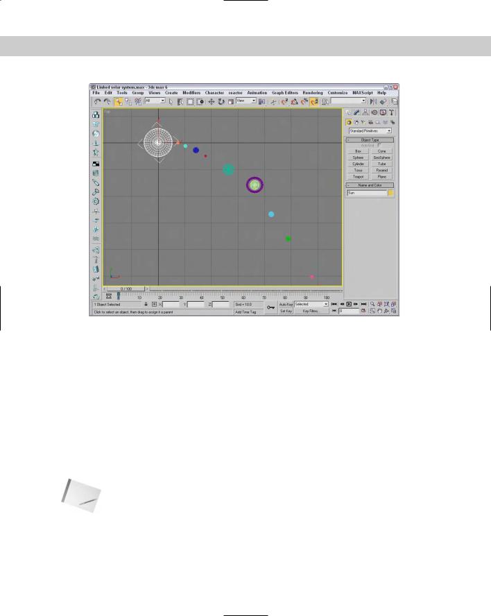
Figure 8-5 shows the planets as they orbit about the sun. The Link button made it possible to rotate all the planets simply by rotating their parent.
Chapter 8 Grouping and Linking Objects 243
Figure 8-5: Linked child planets inherit transformations from their parent sun.
Displaying Links and Hierarchies
The Display panel includes a rollout that lets you display all the links in the viewports.
After links have been established, you can see linked objects listed as a hierarchy in several places. The Select Objects dialog box, opened with the Select by Name button (or with the H key), can display objects in this manner, as well as the Schematic and Track Views.
Displaying links in the viewport
You can select to see the links between the selected objects in the viewports by selecting the Display Links option in the Link Display rollout of the Display panel. The Display Links option shows links as lines that run between the pivot points of the objects with a diamond-shaped marker at the end of each line; these lines and markers are the same color as the object.
Note |
The Display Links option can be enabled or disabled for each object in the scene. To display |
|
the links for all objects, use the Edit Select All (Ctrl+A) command and then enable the |
|
Display Links option. |
244 Part II Working with Objects
The Link Display rollout also offers the Link Replaces Object option, which removes the objects and displays only the link structure. This feature removes the complexity of the objects from the viewports and lets you work with the links directly. Although the objects disappear, you can still transform the objects using the link markers.
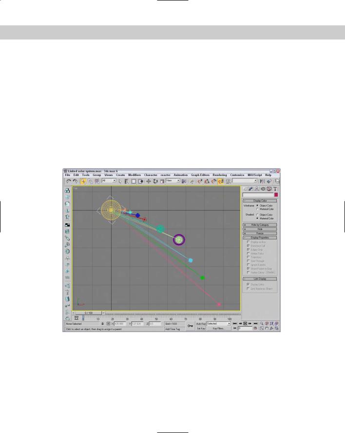
Figure 8-6 shows the solar system that we created in the previous tutorial with the Display Links option enabled for all links.
Viewing hierarchies
The Select Objects dialog box and the Schematic and Track Views can display the hierarchy of objects in a scene as an ordered list, with child objects indented under parent objects.
Clicking the Select by Name button (H) on the main toolbar opens the Select Objects dialog box; click the Display Subtree option to see all the children under the selected object. Figure 8-7 shows the Select Parent dialog box with the Display Subtree option selected.
Figure 8-6: The solar system example with all links visible