


Working with the Schematic View
Avaluable tool for selecting, linking, and organizing scene objects is the Schematic View window. This window offers a 1,000-foot
view of the objects in your scene. From this whole scene perspective, you can find the exact item you seek.
The Schematic View window shows all objects as simple nodes and uses arrows to show relationships between objects. This structure makes the Schematic View window the easiest place to establish links and to wire parameters. You can also use this view to quickly see all the instances of an object.
Using the Schematic View Window
A great way to organize and select objects is by using the Schematic View window. Every object in the Schematic View is displayed as a rectangular box. These boxes, or nodes, are connected to show the relationships among them. You can rearrange them and save the customized views for later access.
New |
The Schematic View window has been overhauled for 3ds max 6. |
Feature |
|
You access the Schematic View window via the Graph Editors menu command or by clicking its button on the main toolbar.
When the window opens, it floats on top of the Max interface and can be moved by dragging its title bar. You can also resize the window by dragging on its borders. The window is modeless and lets you access the viewports and buttons in the interface beneath it.
The Graph Editors menu options
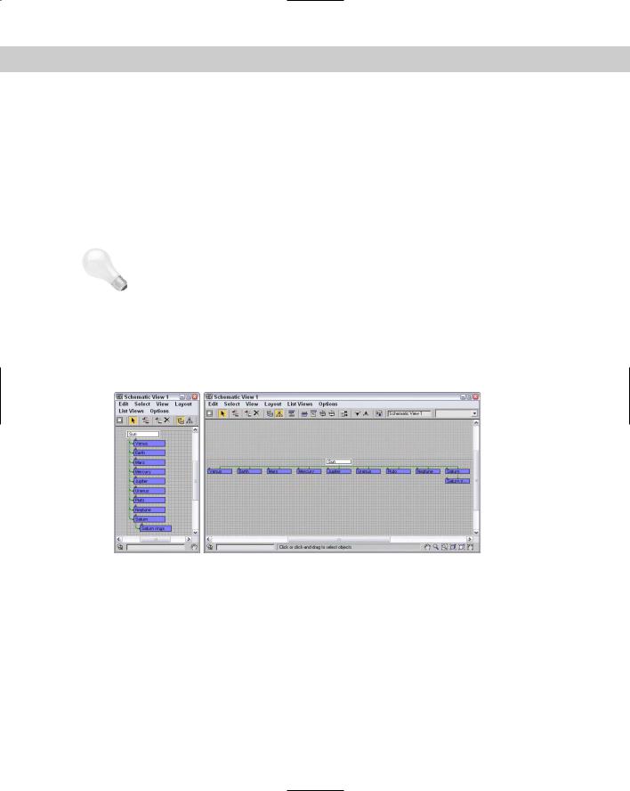
The Schematic View menu options enable you to manage several different views. The Graph Editors New Schematic View command opens the Schematic View window, shown in Figure 9-1. If you enter a name in the View Name field at the top of the window, you can name and save the current view. This name then appears in the Graph Editors Saved Schematic Views submenu and also in the title bar when the saved view is open.
C 9H A P T E R
In This Chapter
Working with the Schematic View window
Working with hierarchies
Setting Schematic View preferences
Using List Views
250 Part II Working with Objects
|
Every time the Graph Editors New Schematic View menu command is used, a new view |
|
name is created and another view is added to the Saved Schematic Views submenu. The |
|
Schematic View Delete Schematic View command opens a dialog box in which you can |
|
select the view you want to delete. |
Tip |
You can open any saved Schematic View window (or a new Schematic View window) within |
|
a viewport by right-clicking the viewport title, choosing Views Schematic, and clicking the |
|
view name in the pop-up menu. |
|
View Name |
Figure 9-1: The Schematic View window displays all objects as nodes.
The Schematic View interface
The Schematic View window includes several common interface elements including menus, toolbar buttons, and a right-click quadmenu. Just like the main interface, you can access the commands in many ways.
Using the Schematic View menus
The Schematic View window includes menus at the top of its interface, including Edit, Select, View, Layout, List Views, and Options.
The Edit menu includes commands to Connect (C) and Unlink Selected object nodes. It also includes a Delete command, which deletes an object from the viewports as well as from the object node. The Edit menu includes features to Assign Controllers, Wire Parameters, and open the Object Properties dialog box.
Note |
Many of the keyboard shortcuts for the Schematic View window are the same as those in the |
|
main interface. If you enable the Keyboard Shortcut Override Toggle on the Extras toolbar, |
|
then you can use the Schematic View keyboard shortcuts. |
Chapter 9 Working with the Schematic View 251
The Select menu includes commands for accessing the Select tool (S); selecting All (Ctrl+A), None (Ctrl+D), and Invert (Ctrl+I); selecting (Ctrl+C) and de-selecting children; and commands to synch the selected nodes in the Schematic View with the scene (Select From Scene) and vice versa (Select to Scene).
The View menu includes commands for selecting the Pan, Zoom, and Zoom Region tools. You can also access the Zoom Extents, Zoom Extents Selected (Z), and Pan to Selected commands. The View menu also includes options to Show/Hide Grid (G), Show/Hide Background, and Refresh View.
The Layout menu includes various options for controlling how the nodes are arranged. The Display Floater (D) command opens the Display floater, which can be used to select the types of nodes to display. The Align submenu lets you align selected nodes to the Left, Right, Top, Bottom, Center Horizontal, or Center Vertical. You can also Expand, Collapse, or Hide Selected, Unhide All, Arrange Children, or Arrange Selected. The Free Selected (Alt+S) and Free All (Alt+F) commands remove nodes from being auto arranged. With the Layout menu, you can also Shrink Selected, Unshrink Selected, Unshrink All, and Toggle Shrink (Ctrl+S).
The List Views menu determines what is shown in the Schematic View. Options include All Relationships, Selected Relationships, All Instances, Selected Instances, Show Occurrences, and All Animated Controllers. Many of these options are also available in the Display Floater.
The Options menu lets you select the Always Arrange option and view mode (either Hierarchy and Reference modes). You can also select the Move Children (Alt+C) option and open the Schematic View Preferences dialog box.
Learning the toolbar buttons
You can also select most of these commands from the toolbar. Many of the toolbar buttons are toggle switches that enable and disable certain viewing modes. The background of these toggle buttons is highlighted yellow when selected. You’ll also find some buttons along the bottom of the window. All Schematic View icon buttons are shown in Table 9-1 and are described in the following sections.
Note |
The Schematic View toolbar buttons are permanently docked to the interface and cannot be |
|
removed. |
Table 9-1: Schematic View Toolbar Buttons
Toolbar Button |
Name |
Description |
|
|
|
|
Display Floater |
Opens the Display Floater, where you can toggle |
|
|
which items are displayed or hidden. |
|
Select (S) |
Toggles selection mode on, where nodes can be |
|
|
selected by clicking. |
|
Connect (C) |
Enables you to create links between objects in the |
|
|
Schematic View window; also used to copy |
|
|
modifiers and materials between objects. |
|
Unlink Selected |
Destroys the link between the selected object |
|
|
and its parent. |
Continued
252 Part II Working with Objects
Table 9-1 (continued)
Toolbar Button |
Name |
Description |
|
|
|
|
Delete Objects |
Deletes the selected object in both the |
|
|
Schematic View and in the viewports. |
|
Hierarchy Mode |
Displays all child objects indented under their |
|
|
parents. |
|
References Mode |
Displays all object references and instances. This |
|
|
mode displays all materials and modifiers |
|
|
associated with the objects. |
|
Always Arrange |
Causes all nodes to be automatically arranged in |
|
|
a hierarchy or in references mode, and disables |
|
|
moving of individual nodes. |
|
Arrange Children |
Automatically rearranges the children of the |
|
|
selected object nodes. |
|
Arrange Selected |
Automatically rearranges the selected object |
|
|
nodes. |
|
Free All |
Allows all objects to be freely moved without |
|
|
being automatically arranged. |
|
Free Selected |
Allows selected objects to be freely moved |
|
|
without being automatically arranged. |
|
Move Children |
Causes children to move along with their parent |
|
|
node. |
|
Expand Selected |
Reveals all nodes below the selected node. |
|
Collapse Selected |
Rolls up all nodes below the selected node. |
|
Preferences |
Opens the Preferences dialog box. |
|
View Name field |
Enter a name into this field to name the current |
|
|
display. Named displays show up underneath the |
|
|
Graph Editors Í Saved Schematic View submenu. |
|
Bookmark Name |
Marks a selection of nodes to which you can |
|
|
return later. |
|
Go to Bookmark |
Zooms and pans to the selected bookmarked |
|
|
objects. |
|
Delete Bookmark |
Removes the bookmark from the Bookmark |
|
|
selection list. |
|
|
|
Chapter 9 Working with the Schematic View 253
Note Most of the menu and toolbar buttons commands are available in a pop-up menu that you can access by right-clicking in the Schematic View window.
Navigating the Schematic View window
As the number of nodes increases, it can become tricky to locate and see the correct node to work with. Along the bottom edge of the Schematic View window are several navigation buttons that work similarly to the Viewport Navigation Control buttons. Using these buttons, you can pan, zoom, and zoom to the extents of all nodes. These buttons are described in Table 9-2.
The Schematic View navigation buttons can also be accessed from within the View menu. These menu commands include Pan Tool, Zoom Tool, Zoom Region Tool, Zoom Extents, Zoom Extents Selected (Z), and Pan to Selected.
Tip You can also navigate the Schematic View window using the mouse and its scroll wheel. Scrubbing the mouse wheel zooms in and out of the window in steps. Holding down the Ctrl key and dragging with the scroll wheel button zooms smoothly in and out of the window. Dragging the scroll wheel pans within the window.
Table 9-2: Schematic View Navigation Buttons
Toolbar Button |
Name |
Description |
|
|
|
|
Zoom Selected |
Zooms in on the nodes that correspond to |
|
Viewport Object |
the selected viewport objects. |
|
Search Name field |
Locates an object node when you type its |
|
|
name. |
|
Pan |
Moves the node view when you drag in |
|
|
the window. |
|
Zoom |
Zooms when you drag the mouse in the |
|
|
window. |
|
Region Zoom |
Zooms to an area selected when you drag |
|
|
an outline. |
|
Zoom Extents |
Increases the window view until all nodes |
|
|
are visible. |
|
Zoom Extents |
Increases the window view until all |
|
Selected |
selected nodes are visible. |
|
Pan to Selected |
Moves the node view at the current zoom |
|
|
level to the selected objects. |
|
|
|
As you navigate the Schematic View window, you can save specific views as bookmarks by typing an identifying name in the Bookmark drop-down list. To recall these views later, select
254 Part II Working with Objects
them from the drop-down list and click the Go to Bookmark icon in the Schematic View toolbar. Bookmarks can be deleted with the Delete Bookmark button.
Working with Schematic View nodes
Every object displayed in the scene has a node — a simple rectangular box that represents the object or attribute. Each node contains a label, and the color of the node depends on the node type.
Node colors
Nodes have a color scheme to help identify them. The colors of various nodes are listed in Table 9-3.
|
Table 9-3: Schematic View Node Colors |
|
|
Color |
Name |
|
|
White |
Selected node |
Blue |
Geometry Object node |
Cyan |
Shape Object node |
Yellow |
Light Object node |
Dark Blue |
Camera Object node |
Green |
Helper Object node |
Purple |
Space Warp Object node |
Goldenrod |
Modifier node |
Dark Yellow |
Base Object node |
Brown |
Material node |
Dark Green |
Map node |
Salmon |
Controller node |
Magenta |
Parameter Wires |
|
|
Note |
If you don’t like any of these colors, you can set the colors used in the Schematic View using |
|
the Colors panel of the Customize User Interface dialog box. |
Selecting nodes
The Select (S) button enters select mode, which lets you select nodes within the Schematic View window by clicking the object node. You can select multiple objects by dragging an outline over them. Holding down the Ctrl key while clicking an object node selects or deselects it. Selected nodes are shown in white.
Chapter 9 Working with the Schematic View 255
The Select menu includes several selection commands that enable you to quickly select (or deselect) many nodes, including Select All (Ctrl+A), Select None (Ctrl+D), Select Invert (Ctlr+I), Select Children (Ctrl+C), and Deselect Children.
If the Select Sync Selection option in the Select menu is enabled, then the node of any object that is selected in the viewports is also selected in the Schematic View window and vice versa. If you disable the Sync Selection option, then you can select different objects in the viewports and in the Schematic View at the same time. The node of the object selected in the viewports is outlined in white, and the interior of selected nodes is white. To select all the objects in the viewports that match the selected nodes without the Sync Selection option enabled, just use Select Select to Scene. Select Select From Scene selects the nodes for all objects selected in the viewports.
Tip |
All animated objects have their node border drawn in red. |
Rearranging nodes
Schematic View includes several options for arranging nodes. In the Options menu, you can toggle between Hierarchy and Reference modes. Hierarchy mode displays the nodes vertically with child objects indented under their parent. Reference mode displays the nodes horizontally allowing for plenty of room to display all the various reference nodes under each parent node. Figure 9-2 shows both of these modes side by side.
Figure 9-2: The Schematic View window can automatically arrange nodes in two different modes: Hierarchy and Reference.
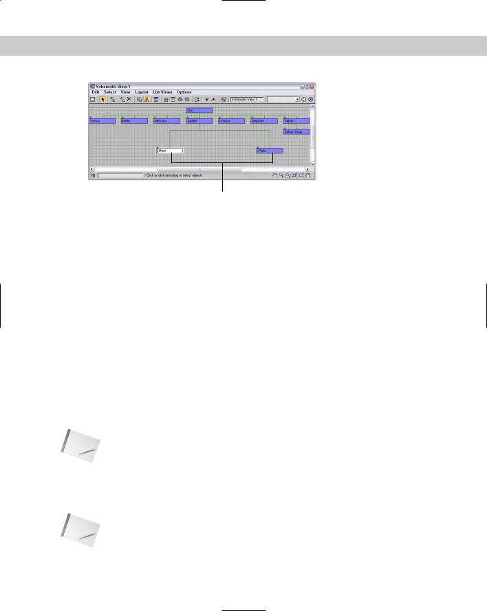
You can move nodes and rearrange them in any order. To move a node, simply click and drag it to a new location. When a node is dragged, all selected nodes move together, and any links follow the node movement. If a child node is moved, all remaining child nodes collapse together to maintain the specified arrangement mode. The moved node then becomes free, which is designated by an open rectangle on the left edge of the node. Figure 9-3 shows two nodes that were moved and thereby became free. The other children automatically moved closer together to close the gaps made by the moving nodes.
256 Part II Working with Objects
Free nodes
Figure 9-3: Free nodes are moved independent of the arranging mode.
Using the Layout Free Selected (Alt+S) and Free All (Alt+F) menu commands, you can free the selected nodes or all nodes. You can also designate that all the children of a node be auto arranged with the Layout Arrange Children menu command or that just the selected nodes be arranged (Layout Arrange Selected). The Options Move Children (Alt+C) command causes all children to be moved along with their parent when the parent is moved. This causes free and non-free nodes to move with their parent.
If the Options Always Arrange option is enabled, then Max automatically arranges all the nodes using either the Hierarchy or Reference mode, but you cannot move any of the nodes while this option is enabled. If you’ve moved any nodes when the Always Arrange option is selected, a dialog box appears telling you that your custom layout will be lost. If the Always Arrange option is enabled, the Arrange Children, Free All (Alt+F), Free Selected (Alt+S), Move Children (Alt+C), and all the Align options are all disabled. If two or more nodes are selected, you can align them using the Layout Align menu. The options include Left, Right, Top, Bottom, Center Horizontal, and Center Vertical.
Hiding, shrinking, and deleting nodes
If your Schematic View window starts to get cluttered, you can always hide nodes to simplify the view. To hide a node, select the nodes to hide and use the Layout Hide Selected menu command. The Layout Unhide All menu command can be used to make the hidden nodes visible again.
Note |
If you hide a parent object, all its children nodes are also hidden. |
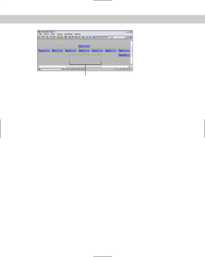
Another useful way to reduce clutter in the Schematic View window is with the Layout Shrink Selected command. This command replaces the rectangular node with a simple dot, but all hierarchical lines to the node are kept intact. Figure 9-4 shows a Schematic View with several shrunk nodes. Shrunk nodes can be unshrunk with the Layout UnShrink Selected and UnShrink All menu commands.
Note |
The Shrink commands work only when Layout Toggle Shrink (Ctrl+S) is enabled. With this |
|
command, you can turn on and off the visibility of shrunken nodes. |
Chapter 9 Working with the Schematic View 257
Shrunk nodes
Figure 9-4: Shrunk nodes appear as simple dots in the
Schematic View.
To delete a node, select the node and click the Delete Objects button on the Schematic View toolbar or press the Delete key. If several nodes are selected, they are all deleted. This deletes the object in the viewports also.
Renaming objects
In the Schematic View window, you can rename objects quickly and conveniently. To rename an object, click a selected node and click again to highlight the text. When the text is highlighted, you can type the new name for the object. This works only for nodes that have a name, which includes materials.
Tutorial: Rearranging the Solar System
To practice moving nodes around, we order the solar system model that was linked in the preceding chapter. When Max places nodes in the Schematic View, it really doesn’t have any specific order that it follows, but you can move them as needed by hand.
To rearrange the solar system nodes, follow these steps.
1.Open the Ordered solar system.max file from the Chap 09 directory on the CD-ROM. This file includes several named spheres representing the solar system.
2.Select Graph Editors New Schematic View to open the Schematic View window. All planets are displayed as blue nodes under the Sun object.
3.Select Options Reference Mode to position all the nodes horizontally. Click the Select tool on the main toolbar (or press the S key).
4.Make sure that the Options Always Arrange option is disabled. Then click and drag the Mercury node to the left, and place it front of the Venus node.
5.Select the Options Move Children (Alt+C) menu command, and drag and drop the Saturn node between the Jupiter and Uranus nodes. With the Move Children option enabled, the Saturn rings node moves with its parent.
6.Drag and drop the Pluto node beyond the Neptune node.