

- •Preface
- •About This Book
- •Acknowledgments
- •Contents at a Glance
- •Contents
- •Relaxing at the Beach
- •Dressing the Scene
- •Animating Motion
- •Rendering the Final Animation
- •Summary
- •The Interface Elements
- •Using the Menus
- •Using the Toolbars
- •Using the Viewports
- •Using the Command Panel
- •Using the Lower Interface Bar Controls
- •Interacting with the Interface
- •Getting Help
- •Summary
- •Understanding 3D Space
- •Using the Viewport Navigation Controls
- •Configuring the Viewports
- •Working with Viewport Backgrounds
- •Summary
- •Working with Max Scene Files
- •Setting File Preferences
- •Importing and Exporting
- •Referencing External Objects
- •Using the File Utilities
- •Accessing File Information
- •Summary
- •Customizing Modify and Utility Panel Buttons
- •Working with Custom Interfaces
- •Configuring Paths
- •Selecting System Units
- •Setting Preferences
- •Summary
- •Creating Primitive Objects
- •Exploring the Primitive Object Types
- •Summary
- •Selecting Objects
- •Setting Object Properties
- •Hiding and Freezing Objects
- •Using Layers
- •Summary
- •Cloning Objects
- •Understanding Cloning Options
- •Mirroring Objects
- •Cloning over Time
- •Spacing Cloned Objects
- •Creating Arrays of Objects
- •Summary
- •Working with Groups
- •Building Assemblies
- •Building Links between Objects
- •Displaying Links and Hierarchies
- •Working with Linked Objects
- •Summary
- •Using the Schematic View Window
- •Working with Hierarchies
- •Setting Schematic View Preferences
- •Using List Views
- •Summary
- •Working with the Transformation Tools
- •Using Pivot Points
- •Using the Align Commands
- •Using Grids
- •Using Snap Options
- •Summary
- •Exploring the Modifier Stack
- •Exploring Modifier Types
- •Summary
- •Exploring the Modeling Types
- •Working with Subobjects
- •Modeling Helpers
- •Summary
- •Drawing in 2D
- •Editing Splines
- •Using Spline Modifiers
- •Summary
- •Creating Editable Mesh and Poly Objects
- •Editing Mesh Objects
- •Editing Poly Objects
- •Using Mesh Editing Modifiers
- •Summary
- •Introducing Patch Grids
- •Editing Patches
- •Using Modifiers on Patch Objects
- •Summary
- •Creating NURBS Curves and Surfaces
- •Editing NURBS
- •Working with NURBS
- •Summary
- •Morphing Objects
- •Creating Conform Objects
- •Creating a ShapeMerge Object
- •Creating a Terrain Object
- •Using the Mesher Object
- •Working with BlobMesh Objects
- •Creating a Scatter Object
- •Creating Connect Objects
- •Modeling with Boolean Objects
- •Creating a Loft Object
- •Summary
- •Understanding the Various Particle Systems
- •Creating a Particle System
- •Using the Spray and Snow Particle Systems
- •Using the Super Spray Particle System
- •Using the Blizzard Particle System
- •Using the PArray Particle System
- •Using the PCloud Particle System
- •Using Particle System Maps
- •Controlling Particles with Particle Flow
- •Summary
- •Understanding Material Properties
- •Working with the Material Editor
- •Using the Material/Map Browser
- •Using the Material/Map Navigator
- •Summary
- •Using the Standard Material
- •Using Shading Types
- •Accessing Other Parameters
- •Using External Tools
- •Summary
- •Using Compound Materials
- •Using Raytrace Materials
- •Using the Matte/Shadow Material
- •Using the DirectX 9 Shader
- •Applying Multiple Materials
- •Material Modifiers
- •Summary
- •Understanding Maps
- •Understanding Material Map Types
- •Using the Maps Rollout
- •Using the Map Path Utility
- •Using Map Instances
- •Summary
- •Mapping Modifiers
- •Using the Unwrap UVW modifier
- •Summary
- •Working with Cameras
- •Setting Camera Parameters
- •Summary
- •Using the Camera Tracker Utility
- •Summary
- •Using Multi-Pass Cameras
- •Creating Multi-Pass Camera Effects
- •Summary
- •Understanding the Basics of Lighting
- •Getting to Know the Light Types
- •Creating and Positioning Light Objects
- •Viewing a Scene from a Light
- •Altering Light Parameters
- •Working with Photometric Lights
- •Using the Sunlight and Daylight Systems
- •Using Volume Lights
- •Summary
- •Selecting Advanced Lighting
- •Using Local Advanced Lighting Settings
- •Tutorial: Excluding objects from light tracing
- •Summary
- •Understanding Radiosity
- •Using Local and Global Advanced Lighting Settings
- •Working with Advanced Lighting Materials
- •Using Lighting Analysis
- •Summary
- •Using the Time Controls
- •Working with Keys
- •Using the Track Bar
- •Viewing and Editing Key Values
- •Using the Motion Panel
- •Using Ghosting
- •Animating Objects
- •Working with Previews
- •Wiring Parameters
- •Animation Modifiers
- •Summary
- •Understanding Controller Types
- •Assigning Controllers
- •Setting Default Controllers
- •Examining the Various Controllers
- •Summary
- •Working with Expressions in Spinners
- •Understanding the Expression Controller Interface
- •Understanding Expression Elements
- •Using Expression Controllers
- •Summary
- •Learning the Track View Interface
- •Working with Keys
- •Editing Time
- •Editing Curves
- •Filtering Tracks
- •Working with Controllers
- •Synchronizing to a Sound Track
- •Summary
- •Understanding Your Character
- •Building Bodies
- •Summary
- •Building a Bones System
- •Using the Bone Tools
- •Using the Skin Modifier
- •Summary
- •Creating Characters
- •Working with Characters
- •Using Character Animation Techniques
- •Summary
- •Forward versus Inverse Kinematics
- •Creating an Inverse Kinematics System
- •Using the Various Inverse Kinematics Methods
- •Summary
- •Creating and Binding Space Warps
- •Understanding Space Warp Types
- •Combining Particle Systems with Space Warps
- •Summary
- •Understanding Dynamics
- •Using Dynamic Objects
- •Defining Dynamic Material Properties
- •Using Dynamic Space Warps
- •Using the Dynamics Utility
- •Using the Flex Modifier
- •Summary
- •Using reactor
- •Using reactor Collections
- •Creating reactor Objects
- •Calculating and Previewing a Simulation
- •Constraining Objects
- •reactor Troubleshooting
- •Summary
- •Understanding the Max Renderers
- •Previewing with ActiveShade
- •Render Parameters
- •Rendering Preferences
- •Creating VUE Files
- •Using the Rendered Frame Window
- •Using the RAM Player
- •Reviewing the Render Types
- •Using Command-Line Rendering
- •Creating Panoramic Images
- •Getting Printer Help
- •Creating an Environment
- •Summary
- •Creating Atmospheric Effects
- •Using the Fire Effect
- •Using the Fog Effect
- •Summary
- •Using Render Elements
- •Adding Render Effects
- •Creating Lens Effects
- •Using Other Render Effects
- •Summary
- •Using Raytrace Materials
- •Using a Raytrace Map
- •Enabling mental ray
- •Summary
- •Understanding Network Rendering
- •Network Requirements
- •Setting up a Network Rendering System
- •Starting the Network Rendering System
- •Configuring the Network Manager and Servers
- •Logging Errors
- •Using the Monitor
- •Setting up Batch Rendering
- •Summary
- •Compositing with Photoshop
- •Video Editing with Premiere
- •Video Compositing with After Effects
- •Introducing Combustion
- •Using Other Compositing Solutions
- •Summary
- •Completing Post-Production with the Video Post Interface
- •Working with Sequences
- •Adding and Editing Events
- •Working with Ranges
- •Working with Lens Effects Filters
- •Summary
- •What Is MAXScript?
- •MAXScript Tools
- •Setting MAXScript Preferences
- •Types of Scripts
- •Writing Your Own MAXScripts
- •Learning the Visual MAXScript Editor Interface
- •Laying Out a Rollout
- •Summary
- •Working with Plug-Ins
- •Locating Plug-Ins
- •Summary
- •Low-Res Modeling
- •Using Channels
- •Using Vertex Colors
- •Rendering to a Texture
- •Summary
- •Max and Architecture
- •Using AEC Objects
- •Using Architectural materials
- •Summary
- •Tutorial: Creating Icy Geometry with BlobMesh
- •Tutorial: Using Caustic Photons to Create a Disco Ball
- •Summary
- •mental ray Rendering System
- •Particle Flow
- •reactor 2.0
- •Schematic View
- •BlobMesh
- •Spline and Patch Features
- •Import and Export
- •Shell Modifier
- •Vertex Paint and Channel Info
- •Architectural Primitives and Materials
- •Minor Improvements
- •Choosing an Operating System
- •Hardware Requirements
- •Installing 3ds max 6
- •Authorizing the Software
- •Setting the Display Driver
- •Updating Max
- •Moving Max to Another Computer
- •Using Keyboard Shortcuts
- •Using the Hotkey Map
- •Main Interface Shortcuts
- •Dialog Box Shortcuts
- •Miscellaneous Shortcuts
- •System Requirements
- •Using the CDs with Windows
- •What’s on the CDs
- •Troubleshooting
- •Index

Chapter 14 Working with Meshes and Polys 419
Figure 14-22: The arms of this octopus were created easily with the Extrude Along Spline feature.
Using Mesh Editing Modifiers
In addition to the editing features available for Editable Mesh and Editable Poly objects, you can also modify their geometries using modifiers. The Modifiers menu includes a submenu of modifiers that are specific to mesh (and poly) objects. These modifiers are found in the Mesh Editing submenu and can be used to enhance the features available for these objects.
Cross- |
You can find a more general explanation of modifiers in Chapter 11, “Introducing Modifiers |
Reference |
for Basic Object Deformation.” |
|
Edit Mesh modifier
All mesh objects are by default Editable Mesh objects. This modifier enables objects to be modified using the Editable Mesh feature while maintaining their basic creation parameters.
When an object is converted to an Editable Mesh, its parametric nature is eliminated. However, if you use the Edit Mesh modifier, you can still retain the same object type and its parametric nature while having access to all the Editable Mesh features. For example, if you
420 Part III Modeling
create a sphere and apply the Edit Mesh modifier and then extrude several faces, you can still change the radius of the sphere by selecting the Sphere object in the Modifier Stack and changing the Radius value in the Parameters rollout.
Caution |
No Edit Poly modifier is available. |
Cap Holes modifier
The Cap Holes modifier patches any holes found in a geometry object. Sometimes when objects are imported, they are missing faces. This modifier can detect and eliminate these holes by creating a face along open edges.
For example, if a spline is extruded and you don’t specify Caps, then the extruded spline has holes at its end. The Cap Holes modifier detects these holes and creates a Cap. Cap Holes parameters include Smooth New Faces, Smooth with Old Faces, and Triangulate Cap. Smooth with Old Faces applies the same smoothing group used on the bordering faces.
Delete Mesh modifier
You can use the Delete Mesh modifier to delete mesh subobjects. Subobjects that you can delete include Vertices, Edges, Faces, and Objects. The nice part about the Delete Mesh modifier is that it remains in the Modifier Stack and can be removed to reinstate the deleted subobjects.
The Delete Mesh modifier deletes the current selection as defined by the Mesh Select (or Poly Select) modifier. It can be used to delete a selection of Vertices, Edges, Faces, Polygons, or even the entire mesh if there is no subobject selection. The Delete Mesh modifier has no parameters.
Note |
Even if the entire mesh is deleted using the Delete Mesh modifier, the object still remains. To |
|
completely delete an object, use the Delete key. |
Edit Normals
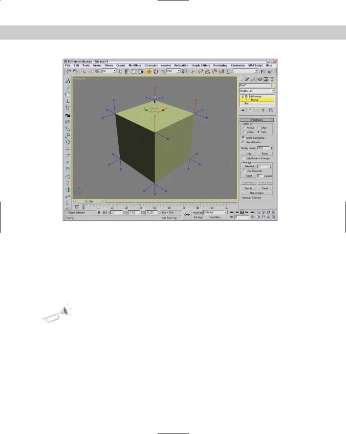
The Edit Normals modifier enables you to select and move normals. Normals appear as blue lines that extend from the vertex of each face. The Edit Normal modifier includes a Normals subobject that you can select and change its direction. To move (or rotate) a normal, you can use the transform tools on the main toolbar. If your viewport has shading enabled, you can see the effect of moving the normals.
You can Select normals by Normal, Edge, Vertex, or Face. Selecting normals by Face, for instance, selects all normals attached to a face when you click on a face. Moving a normal then moves all selected normals together.
You also have options to Ignore Backfacing and to Show Handles. Handles appear as small squares at the top of the normal vector. The Display Length value defines the length of the normals displayed in the viewports. Figure 14-23 shows all the normals extending from a simple Box object.
Chapter 14 Working with Meshes and Polys 421
Figure 14-23: The Edit Normals Parameters let you work with normals.
The modifier also includes buttons to Unify and to Break selected normals. Unify causes all selected normals to be combined to a single normal, and Break splits unified normals into their separate components again. The direction of the unified normal is an average of the surface points when unified or an average of the normals if the Unify/Break to Average option is enabled.
The Average Selected button averages all selected normals that are within the specified value if the Use Threshold value is enabled. If it is not enabled, then all selected normals are averaged. The Average Target button lets you interactively select a normal and then click on another normal to average. The Target normal must be within the specified Target value.
New |
The Average section is new to 3ds max 6. |
Feature |
|
The direction of selected normals can be copied and pasted between normals. The Specify button marks a normal as a Specified normal. These normals appear cyan in the viewport and ignore any smoothing group information associated with the vertex. Explicit normals are green in the viewport, which denotes a normal that has deviated from its regular position. The Make Explicit button can be used to make normals explicit, thereby removing them from the normal computation task. The Reset button returns a normal to its regular type and position. At the bottom of the Parameters rollout is an information line that displays which normal is selected or how many normals are selected.
422 Part III Modeling
Extrude modifier
The Extrude modifier can be applied only to spline or shape objects, but the resulting extrusion can be a Patch, Mesh, or NURBS object. This modifier copies the spline, moves it a given distance, and connects the two splines to form a 3D shape. Parameters for this modifier include an Amount value, which is the distance to extrude, and the number of segments to use to define the height. The Capping options let you specify a Start Cap and/or an End Cap. The Cap fills the spline area and can be made as a Patch, Mesh, or NURBS object. Only closed splines that are extruded can be capped. You can also have mapping coordinates and Material IDs generated automatically. The Smooth option smoothes the extrusion.
Cross- |
Chapter 13, “Drawing and Editing 2D Splines and Shapes,” includes a good example of the |
Reference |
Extrude modifier. |
|
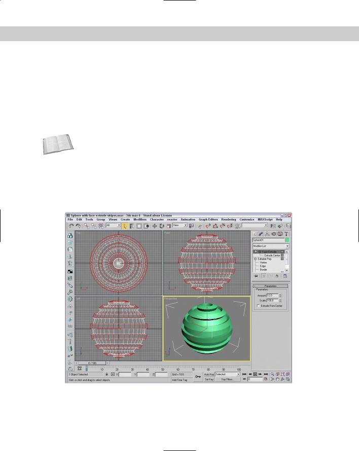
Face Extrude modifier
The Face Extrude modifier extrudes the selected faces in the same direction as their normals. Face Extrude parameters include Amount and Scale values and an option to Extrude From Center. Figure 14-24 shows a mesh object with several extruded faces. The Mesh Select modifier was used to select the faces, and the extrude Amount was set to 30.
Figure 14-24: Extruded faces are moved in the direction of the face normal.

Chapter 14 Working with Meshes and Polys 423
Tutorial: Extruding a bullet
As a simple example that uses a couple of Mesh modifiers, we create a single bullet using a hemisphere object. You can create this simple object in other ways, but this offers some good practice.
To create a bullet using the Face Extrude modifier, follow these steps:
1.Select Create Standard Primitives Sphere, and drag in the Top viewport to create a sphere object. Set the Radius value to 60 and the Hemisphere value to 0.5 to create half a sphere.
2.Right-click on the sphere object, and select Convert To Editable Poly in the pop-up quadmenu to convert the hemisphere to an Editable Poly object.
3.Select the Top viewport, right-click on the viewport name, and select Views Bottom from the pop-up menu (or press the B key) to switch to the Bottom view.
4.In the Selection rollout, click the Vertex button to enter Vertex subobject mode and enable the Ignore Backfacing option. Then select the single vertex in the center of the hemisphere, and press the Delete key.
5.In the Selection rollout, click the Border button to enter Border subobject mode and click on the edge of the hemisphere to select the border of the hole that was created by deleting the center vertex. Then click on the Cap button in the Edit Borders rollout.
6.Select the Polygon button in the Selection rollout to enter Polygon subobject mode. Then select Modifiers Mesh Editing Face Extrude to apply the Face Extrude modifier to the selected polygon face. Set the Amount value to 200.
7.Select Create Standard Primitives Cylinder, and drag in the Bottom viewport to create a thin Cylinder object that is just wider than the extruded hemisphere. Then move the new Cylinder object until it is positioned at the end of the bullet object.
Figure 14-25 shows the completed simple bullet.
MultiRes modifier
You can use the MultiRes modifier to create lower resolution versions of a mesh object. This modifier is especially useful for creating real-time updated meshes for the gaming market. Once applied to a mesh object using the Modifier List in the Modify panel, you can set the desired options in the Generation Parameters section of the MultiRes Parameters rollout and click the Generate button to apply the MultiRes solution to the selected object.
The Vertex Merging option maintains continuity between vertices within the mesh. When enabled, vertices within the Threshold value are welded as the mesh is reduced. The Within Mesh option collapses the boundaries of adjacent elements. The Boundary Metric option looks for boundaries where different materials are applied and tries to maintain these boundaries.
The MultiRes modifier includes a single subobject: Vertex. Using this subobject mode, you can select vertices that you don’t want to change. These selected subobject vertices are not altered if the Maintain Base Vertices option is enabled. The Crease Angle value can be used to maintain sharp edges. If any of the options are changed, you can update the solution by clicking the Generation button again.

424 Part III Modeling
Figure 14-25: A simple bullet can be created by extruding one face of a hemisphere.
Once generated, you can use the Vertex Percent and Vertex Count spinners to control the mesh complexity. The viewport displays the updated mesh as you change its complexity. The rollout displays the number of vertices and faces. The Max Vertex and Max Face fields are the number of vertices and faces in the original mesh; the Face Count is the current number of faces.
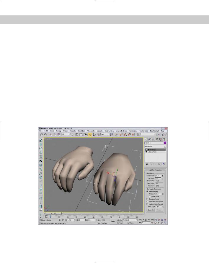
Tutorial: Creating a MultiRes hand
You can use the Optimize modifier to quickly create the lower resolution models, but the MultiRes modifier offers more functionality and enables you to dynamically dial down the resolution to exactly what you want. In this example, we use the MultiRes modifier on a high-res hand model created by Viewpoint Datalabs. The hand weighs in at 2,906 polygons, which is a little heavy for any game engine.
To create a MultiRes hand, follow these steps:
1.Open the MultiRes hand.max file from the Chap 14 directory on the CD-ROM. This file contains a simple hand model.
2.With the hand selected, choose MultiRes from the Modifier List to apply the modifier to the hand model.
Chapter 14 Working with Meshes and Polys 425
3.In the MultiRes Parameters rollout, enable the Vertex Merging option and set the Threshold to 0.05. Also enable the Boundary Metric and Multiple Vertex Normals options, and set the Crease Angle to 75. Then click the Generate button.
4.Create a copy of the hand by holding down the Shift key and dragging the hand to the right. In the Clone Options dialog box that appears, select Copy, name the clone Hand – Lo, and click OK.
5.With the cloned hand selected, set the Vert Percent to 10.
Notice that the number of faces has dropped from over 2,906 to 302.
Figure 14-26 shows the results of the MultiRes modifier. If you look closely, you can see that the hand on the right isn’t as smooth, but it still looks pretty good and the game engine won’t complain.
Normal modifier
The Normal modifier is the precursor to the Edit Normals modifier. It enables object normals to be flipped or unified. When some objects are imported, their normals can become erratic, producing holes in the geometry. By unifying and flipping the normals, you can restore an object’s consistency. This modifier includes only two options: Unify Normals and Flip Normals.
Figure 14-26: You can use the MultiRes modifier to dynamically dial back the complexity of a mesh.

426 Part III Modeling
Optimize modifier
The Optimize modifier isn’t as robust as the MultiRes modifier, but it roughly accomplishes the same function — reducing the overall number of polygons. It does the opposite of the Tessellation modifier. It simplifies models by reducing the number of faces, edges, and vertices. The Level of Detail can be set differently for the Renderer and the Viewports. Face and Edge Thresholds determine whether elements should be collapsed. Other options include Bias and Maximum Edge Length. Parameters can also be set to Preserve Material and Smoothing Boundaries. The Update button enables manual updating of the object, and the text field at the bottom of the rollout displays the number of vertices and faces for the current optimization.
Figure 14-27 shows an alligator model that has been optimized. Notice the dramatic reduction in the number of faces from the left to the right. Viewpoint Datalabs, known for producing high-resolution models, created this model. At the bottom of the Modify panel, the number of faces has been reduced from 34,404 to 10,140 faces by setting the Face Threshold to 15 and the Edge Threshold to 3.0. (I guess that would make the gator on the right “lean and mean”).
Figure 14-27: You can use the Optimize modifier to reduce the complexity of the alligator model.

Chapter 14 Working with Meshes and Polys 427
Smooth modifier
You can use the Smooth modifier to auto-smooth an object. Smooth parameters include options for Auto Smooth and Prevent Indirect Smoothing along with a Threshold value.
The Parameters rollout also includes a set of 32 Smoothing Groups buttons labeled 1 through 32. These same Smoothing Groups are available as options for the Polygon and Element subobjects.
STL Check modifier
The STL Check modifier checks a model in preparation for exporting it to the StereoLithography (STL) format. StereoLithography files require a closed surface — geometry with holes or gaps can cause problems. Any problems are reported in the Status area of the Parameters rollout.
This modifier can check for several common errors, including Open Edge, Double Face, Spike, or Multiple Edge. Spikes are island faces with only one connected edge. You can select any or all of these options. If found, you can have the modifier select the problem Edges or Faces, or neither, or you can change the Material ID of the problem area.
Symmetry modifier
The Symmetry modifier allows you to mirror a mesh object across a single axis. You can also select to Slice Along Mirror and weld along the seam with a defined Threshold. The gizmo for this modifier is a plane, which matches the selected axis and the arrow vector that extends from the plane.
Tessellate modifier
You use the Tessellate modifier to subdivide the selected faces for higher-resolution models. You can apply tessellation to either Triangle or Polygonal faces. The Edge option creates new faces by dividing the face from the face center to the middle of the edges. The Face-Center option divides each face from the face center to the corners of the face. The Tension setting determines whether the faces are convex or concave. The Iterations setting is the number of times the modifier is applied.
Caution |
Applying the Tessellate modifier to an object with a high Iterations value produces objects |
|
with many times the original number of faces. |
Vertex Weld modifier
The Vertex Weld modifier is a simple modifier that welds all vertices within a certain Threshold value. This is a convenient modifier for cleaning up mesh objects.
Subdivision Surface modifiers
The Modifiers menu also includes a submenu of modifiers for subdividing surfaces. These include the MeshSmooth and HSDS Modifiers. You can use these modifiers to smooth and subdivide the surface of an object. Subdividing a surface increases the resolution of the object, allowing for more detailed modeling.

428 Part III Modeling
MeshSmooth modifier
The MeshSmooth modifier smoothes the entire surface of an object by applying a chamfer function to both vertices and edges at the same time. This modifier has the greatest effect on sharp corners and edges. With this modifier, you can create a NURMS object. NURMS stands for Non-Uniform Rational MeshSmooth. NURMS can weight each control point. The Parameters rollout includes three MeshSmooth types: Classic, NURMS, and Quad Output. You can set it to operate on triangular or polygonal faces. Smoothing parameters include Strength and Relax values.
There are also settings for the number of Subdivision Iterations to run and controls for weighting selected control points. Update Options can be set to Always, When Rendering, and Manually using the Update button. You can also select and work with either Vertex or Edge subobjects. These subobjects give you local control over the MeshSmooth object. Included within the Local Control rollout is a Crease value, which is available in Edge subobject mode. Selecting an Edge subobject and applying a 1.0 value causes a hard edge to be retained while the rest of the object is smoothed. The MeshSmooth modifier also makes the Soft Selection rollout available. The Reset rollout is included to quickly reset any crease and weight values.
Tutorial: Creating a heart-shaped NURMS
Here’s an example just for Valentine’s Day. Create a spline heart, extrude it, and then convert it to a NURMS object using the MeshSmooth modifier.
To create a heart-shaped NURMS object, follow these steps:
1.Open the Heart shaped NURMS.max file from the Chap 14 directory on the CD-ROM. This file includes a simple extruded heart shape.
2.With the heart shape selected, choose Modifiers Subdivision Surfaces MeshSmooth to apply the MeshSmooth modifier. In the Subdivision Method rollout, select the NURMS option in the Subdivision Method drop-down list (if it isn’t already selected).
3.In the Local Control rollout, select the Edge subobject icon and click in the Front viewport on the single edge at the center of the heart shape. Then set the Crease value to 1.0. Click the Edge subobject again to exit subobject mode.
4.To apply the smoothing option to the entire object, select an Iterations value of 1 in the Subdivision Amount rollout.
The entire heart is smoothed with the exception of the crease located at the center of the heart.
5.In the Local Control rollout, select the Display Control Mesh option, click the Vertex subobject button, select the two vertices at the heart’s center (the bottom of the crease), and increase the Weight value to 100.
The faces gravitate toward the selected vertices.
Figure 14-28 shows the NURMS heart.