

- •Preface
- •About This Book
- •Acknowledgments
- •Contents at a Glance
- •Contents
- •Relaxing at the Beach
- •Dressing the Scene
- •Animating Motion
- •Rendering the Final Animation
- •Summary
- •The Interface Elements
- •Using the Menus
- •Using the Toolbars
- •Using the Viewports
- •Using the Command Panel
- •Using the Lower Interface Bar Controls
- •Interacting with the Interface
- •Getting Help
- •Summary
- •Understanding 3D Space
- •Using the Viewport Navigation Controls
- •Configuring the Viewports
- •Working with Viewport Backgrounds
- •Summary
- •Working with Max Scene Files
- •Setting File Preferences
- •Importing and Exporting
- •Referencing External Objects
- •Using the File Utilities
- •Accessing File Information
- •Summary
- •Customizing Modify and Utility Panel Buttons
- •Working with Custom Interfaces
- •Configuring Paths
- •Selecting System Units
- •Setting Preferences
- •Summary
- •Creating Primitive Objects
- •Exploring the Primitive Object Types
- •Summary
- •Selecting Objects
- •Setting Object Properties
- •Hiding and Freezing Objects
- •Using Layers
- •Summary
- •Cloning Objects
- •Understanding Cloning Options
- •Mirroring Objects
- •Cloning over Time
- •Spacing Cloned Objects
- •Creating Arrays of Objects
- •Summary
- •Working with Groups
- •Building Assemblies
- •Building Links between Objects
- •Displaying Links and Hierarchies
- •Working with Linked Objects
- •Summary
- •Using the Schematic View Window
- •Working with Hierarchies
- •Setting Schematic View Preferences
- •Using List Views
- •Summary
- •Working with the Transformation Tools
- •Using Pivot Points
- •Using the Align Commands
- •Using Grids
- •Using Snap Options
- •Summary
- •Exploring the Modifier Stack
- •Exploring Modifier Types
- •Summary
- •Exploring the Modeling Types
- •Working with Subobjects
- •Modeling Helpers
- •Summary
- •Drawing in 2D
- •Editing Splines
- •Using Spline Modifiers
- •Summary
- •Creating Editable Mesh and Poly Objects
- •Editing Mesh Objects
- •Editing Poly Objects
- •Using Mesh Editing Modifiers
- •Summary
- •Introducing Patch Grids
- •Editing Patches
- •Using Modifiers on Patch Objects
- •Summary
- •Creating NURBS Curves and Surfaces
- •Editing NURBS
- •Working with NURBS
- •Summary
- •Morphing Objects
- •Creating Conform Objects
- •Creating a ShapeMerge Object
- •Creating a Terrain Object
- •Using the Mesher Object
- •Working with BlobMesh Objects
- •Creating a Scatter Object
- •Creating Connect Objects
- •Modeling with Boolean Objects
- •Creating a Loft Object
- •Summary
- •Understanding the Various Particle Systems
- •Creating a Particle System
- •Using the Spray and Snow Particle Systems
- •Using the Super Spray Particle System
- •Using the Blizzard Particle System
- •Using the PArray Particle System
- •Using the PCloud Particle System
- •Using Particle System Maps
- •Controlling Particles with Particle Flow
- •Summary
- •Understanding Material Properties
- •Working with the Material Editor
- •Using the Material/Map Browser
- •Using the Material/Map Navigator
- •Summary
- •Using the Standard Material
- •Using Shading Types
- •Accessing Other Parameters
- •Using External Tools
- •Summary
- •Using Compound Materials
- •Using Raytrace Materials
- •Using the Matte/Shadow Material
- •Using the DirectX 9 Shader
- •Applying Multiple Materials
- •Material Modifiers
- •Summary
- •Understanding Maps
- •Understanding Material Map Types
- •Using the Maps Rollout
- •Using the Map Path Utility
- •Using Map Instances
- •Summary
- •Mapping Modifiers
- •Using the Unwrap UVW modifier
- •Summary
- •Working with Cameras
- •Setting Camera Parameters
- •Summary
- •Using the Camera Tracker Utility
- •Summary
- •Using Multi-Pass Cameras
- •Creating Multi-Pass Camera Effects
- •Summary
- •Understanding the Basics of Lighting
- •Getting to Know the Light Types
- •Creating and Positioning Light Objects
- •Viewing a Scene from a Light
- •Altering Light Parameters
- •Working with Photometric Lights
- •Using the Sunlight and Daylight Systems
- •Using Volume Lights
- •Summary
- •Selecting Advanced Lighting
- •Using Local Advanced Lighting Settings
- •Tutorial: Excluding objects from light tracing
- •Summary
- •Understanding Radiosity
- •Using Local and Global Advanced Lighting Settings
- •Working with Advanced Lighting Materials
- •Using Lighting Analysis
- •Summary
- •Using the Time Controls
- •Working with Keys
- •Using the Track Bar
- •Viewing and Editing Key Values
- •Using the Motion Panel
- •Using Ghosting
- •Animating Objects
- •Working with Previews
- •Wiring Parameters
- •Animation Modifiers
- •Summary
- •Understanding Controller Types
- •Assigning Controllers
- •Setting Default Controllers
- •Examining the Various Controllers
- •Summary
- •Working with Expressions in Spinners
- •Understanding the Expression Controller Interface
- •Understanding Expression Elements
- •Using Expression Controllers
- •Summary
- •Learning the Track View Interface
- •Working with Keys
- •Editing Time
- •Editing Curves
- •Filtering Tracks
- •Working with Controllers
- •Synchronizing to a Sound Track
- •Summary
- •Understanding Your Character
- •Building Bodies
- •Summary
- •Building a Bones System
- •Using the Bone Tools
- •Using the Skin Modifier
- •Summary
- •Creating Characters
- •Working with Characters
- •Using Character Animation Techniques
- •Summary
- •Forward versus Inverse Kinematics
- •Creating an Inverse Kinematics System
- •Using the Various Inverse Kinematics Methods
- •Summary
- •Creating and Binding Space Warps
- •Understanding Space Warp Types
- •Combining Particle Systems with Space Warps
- •Summary
- •Understanding Dynamics
- •Using Dynamic Objects
- •Defining Dynamic Material Properties
- •Using Dynamic Space Warps
- •Using the Dynamics Utility
- •Using the Flex Modifier
- •Summary
- •Using reactor
- •Using reactor Collections
- •Creating reactor Objects
- •Calculating and Previewing a Simulation
- •Constraining Objects
- •reactor Troubleshooting
- •Summary
- •Understanding the Max Renderers
- •Previewing with ActiveShade
- •Render Parameters
- •Rendering Preferences
- •Creating VUE Files
- •Using the Rendered Frame Window
- •Using the RAM Player
- •Reviewing the Render Types
- •Using Command-Line Rendering
- •Creating Panoramic Images
- •Getting Printer Help
- •Creating an Environment
- •Summary
- •Creating Atmospheric Effects
- •Using the Fire Effect
- •Using the Fog Effect
- •Summary
- •Using Render Elements
- •Adding Render Effects
- •Creating Lens Effects
- •Using Other Render Effects
- •Summary
- •Using Raytrace Materials
- •Using a Raytrace Map
- •Enabling mental ray
- •Summary
- •Understanding Network Rendering
- •Network Requirements
- •Setting up a Network Rendering System
- •Starting the Network Rendering System
- •Configuring the Network Manager and Servers
- •Logging Errors
- •Using the Monitor
- •Setting up Batch Rendering
- •Summary
- •Compositing with Photoshop
- •Video Editing with Premiere
- •Video Compositing with After Effects
- •Introducing Combustion
- •Using Other Compositing Solutions
- •Summary
- •Completing Post-Production with the Video Post Interface
- •Working with Sequences
- •Adding and Editing Events
- •Working with Ranges
- •Working with Lens Effects Filters
- •Summary
- •What Is MAXScript?
- •MAXScript Tools
- •Setting MAXScript Preferences
- •Types of Scripts
- •Writing Your Own MAXScripts
- •Learning the Visual MAXScript Editor Interface
- •Laying Out a Rollout
- •Summary
- •Working with Plug-Ins
- •Locating Plug-Ins
- •Summary
- •Low-Res Modeling
- •Using Channels
- •Using Vertex Colors
- •Rendering to a Texture
- •Summary
- •Max and Architecture
- •Using AEC Objects
- •Using Architectural materials
- •Summary
- •Tutorial: Creating Icy Geometry with BlobMesh
- •Tutorial: Using Caustic Photons to Create a Disco Ball
- •Summary
- •mental ray Rendering System
- •Particle Flow
- •reactor 2.0
- •Schematic View
- •BlobMesh
- •Spline and Patch Features
- •Import and Export
- •Shell Modifier
- •Vertex Paint and Channel Info
- •Architectural Primitives and Materials
- •Minor Improvements
- •Choosing an Operating System
- •Hardware Requirements
- •Installing 3ds max 6
- •Authorizing the Software
- •Setting the Display Driver
- •Updating Max
- •Moving Max to Another Computer
- •Using Keyboard Shortcuts
- •Using the Hotkey Map
- •Main Interface Shortcuts
- •Dialog Box Shortcuts
- •Miscellaneous Shortcuts
- •System Requirements
- •Using the CDs with Windows
- •What’s on the CDs
- •Troubleshooting
- •Index

712 Part VI Lighting
Summary
I hope you have found this chapter enlightening. (Sorry about the bad pun, but I need to work them in where I can.) Max has many different lights, each with plenty of controls. Learning to master these controls can take you a long way toward increasing the realism of the scene. In this chapter, you’ve
Learned the basics of lighting
Discovered Max’s light types
Created and positioned light objects
Learned to change the viewport view to a light
Used the Sunlight and Daylight systems
Learned to use Photometric lights
Used the Volume Light atmospheric effect
Added projection maps to lights
Used raytraced shadows to create a stained-glass window
In the next chapter, we cover one aspect of advanced lighting — light tracing.
|
|
|

Advanced Lighting
and Light Tracing
If you were to walk into a dark room and reach for the light switch, you would be confused if you found a separate switch that controlled the advanced lighting. But in Max the advanced lighting con-
trols are worth the trouble. They enable you to take your lighting solution to the next level.
The advanced lighting controls in Max enable you to light scenes using two separate global illumination techniques known as light tracing and radiosity.
This chapter concentrates on the light tracing method. Light tracing is typically used for outdoor scenes where the light consists of a single powerful light source at a far distance from the scene. Light tracing computes a solution based on bouncing light and includes support for color bleeding between surfaces. Another aspect of light tracing is that the shadows are softer.
Selecting Advanced Lighting
You control the advanced lighting settings for the scene in the Advanced Lighting panel, which is part of the Render Scene dialog box. You can access this panel by selecting Rendering Advanced Lighting Light Tracer (or by pressing the 9 key). The Advanced Lighting panel includes a rollout with a single drop-down list where you can select the lighting plug-in to use. The options are None, Light Tracer, and Radiosity.
Cross- |
Radiosity is useful for indoor lighting and is covered in Chapter 29, |
Reference |
“Advanced Lighting and Radiosity.” |
|
These two options are two different techniques for applying advanced lighting to a scene. Although they are fundamentally different, they both simulate a critical piece of the lighting puzzle that adds dramatically to the realism of the lights in the scene — light bouncing. When light strikes a surface in real life, a portion of the light bounces off the surface and illuminates other surfaces. Traditionally, Max hasn’t worried about this, which required that users add more lights to the scene to account for this additional lighting. Both the Light Tracer and the Radiosity solutions include light bouncing in their calculations.
28C H A P T E R
In This Chapter
Using advanced lighting
Understanding light tracing
Setting local advanced lighting parameters
Using the Advanced Lighting Override material
714 Part VI Lighting
How light tracing works
The Light Tracer is a Global Illumination (GI) system that is similar to raytracing, but it focuses more on calculating how light bounces off surfaces in the scene. The results are fairly realistic without being computationally expensive, and its solutions are rendered much quicker than a radiosity solution.
Cross- |
The Light Tracer is similar in many ways to raytracing. Chapter 44, “Raytracing and mental |
Reference |
ray,” presents more information on raytracing. |
|
The Light Tracer works by dividing the scene into sample points. These sample points are more heavily concentrated along the edges of objects in the scene. An imaginary light ray is then shot at each sample point, and the light intensity at the location of contact is recorded; then it is computed where the light ray would bounce to, and a reduced intensity value is recorded. One of the settings is how many times the light rays will bounce within the scene, and this value increases the amount of time required to compute the solution. When all the rays and light bounces have been computed, the total light intensity value for each sample point is totaled and averaged.
Caution |
Transparent objects split each ray in two. One ray bounces, and the second ray is projected |
|
through the transparent object. Transparent objects in the scene quickly double the amount |
|
of time required to compute a solution. |
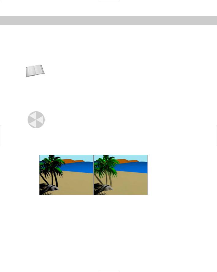
The end result of a light tracing solution is that objects that are typically hidden in the shadows become much easier to see. Figure 28-1 shows a beach scene that was rendered using the standard lighting solution with raytraced shadows and then again using the Light Tracer. Notice that many of the details hidden in the shadows of one figure are visible in the other.
Figure 28-1: A beach scene rendered using standard lighting (left) and light tracing (right).
Enabling light tracing
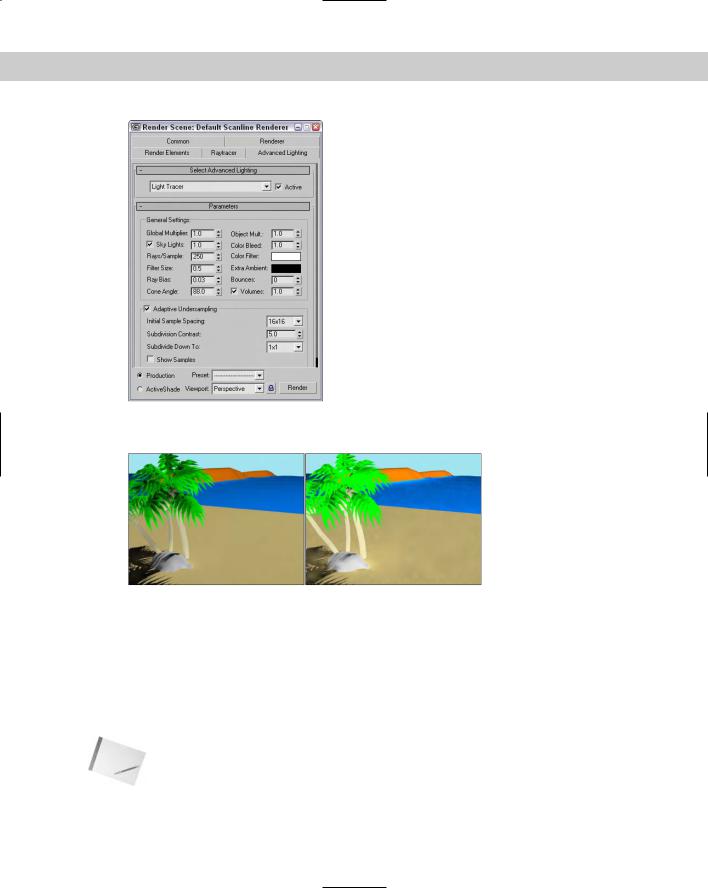
To enable light tracing in a scene, Select Rendering Advanced Lighting Light Tracer to open the Advanced Lighting panel in the Render Scene dialog box, as shown in Figure 28-2.
The Global Multiplier value increases the overall effect of the Light Tracer, much like increasing the multiplier of a light. The net result is to brighten the scene. You can also increase the multiplier of skylights with the Sky Lights values. The Object Multiplier sets the amount of light energy that bounces off the objects. Figure 28-3 shows the beach scene with an Object Multiplier value of 5.0 (left) and 25.0 (right).
Chapter 28 Advanced Lighting and Light Tracing |
715 |
Figure 28-2: The Light Tracer Parameters rollout sets values for GI lighting.
Figure 28-3: Increasing the Object Multiplier value increases the amount of light energy that bounces off objects.
Color bleeding
Another characteristic of global illumination is color bleeding. As a light ray strikes the surface of an object and bounces, it carries the color of the object that is struck with it to the next object. The result of this is that colors from one object bleed onto adjacent objects. You can control this effect using the Color Bleed setting. You can greatly exaggerate the amount of color bleeding by increasing the Object Multiplier along with the Color Bleed value. You can also select colors to use for a color filter and for extra ambient light.
Note |
The color bleeding effect doesn’t happen unless the Bounce value is set to 2 or greater. |
716 Part VI Lighting
When using color bleeding, you want also to enable the Exposure Control to the scene. Exposure Control is found in the Environment panel (keyboard shortcut, 8), which can be opened with the Rendering Environment menu command.
Cross- |
The Exposure Control features are discussed in Chapter 41, “Rendering Basics.” |
Reference |
|
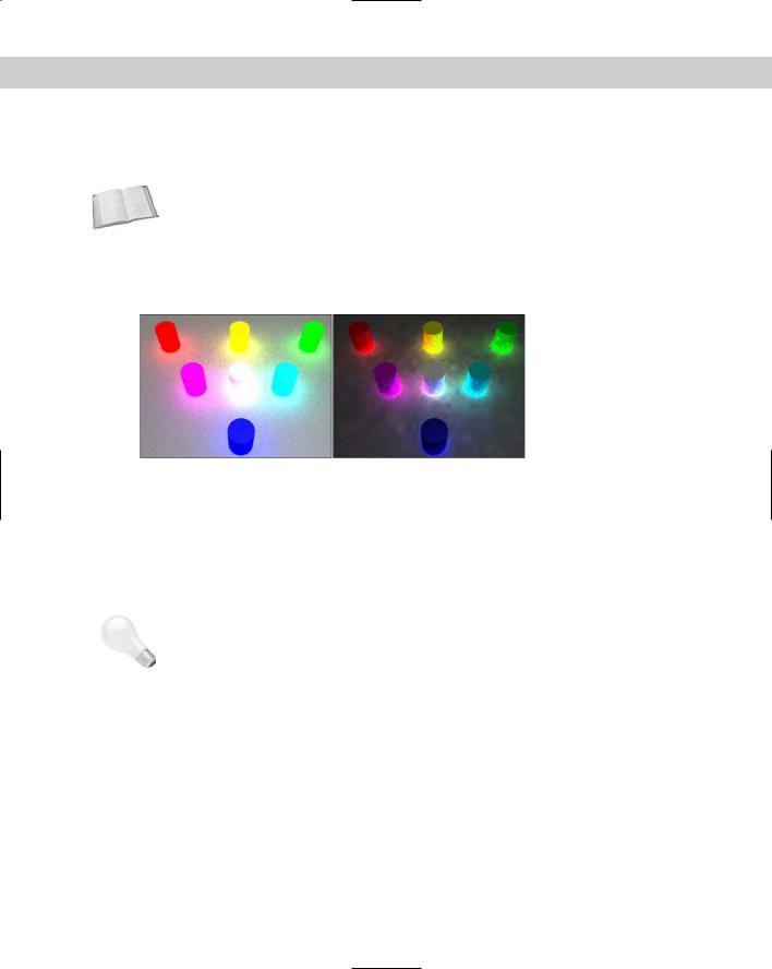
Figure 28-4 shows an example of color bleeding with several colored cylinders projecting from a gray Box object. The Object Multiplier value was set to 4.0, and the Color Bleed was set a maximum value of 25.0 with a Bounce value of 3. Using the Exposure Control settings, you can isolate the color bleed.
Figure 28-4: Color bleeding spreads color about the scene. Exposure
Control can highlight it with Automatic (left) and Logarithmic (right).
|
Quality versus speed |
|
The big trade-off of global illumination is between quality and render time. The more rays per |
|
sample that you specify, the better the quality and the longer the render time. This is con- |
|
trolled with the Rays/Sample setting. The Rays/Sample setting and the number of Bounces |
|
dramatically increase the rendering time. The Ray Bias setting biases rays toward object |
|
edges versus flat areas. |
Tip |
If you want to see a preview of your scene using light tracing, set the Rays/Sample value to |
|
around 10 percent of its normal value and render the scene. The resulting image is grainy, |
|
but it shows a rough approximation of the scene lighting without having to change the |
|
Bounce value. |
|
If you don’t include enough rays in the scene, then noise patterns appear within the scene. |
|
The Filter Size can help control the amount of noise that appears in the scene. |
|
The number of Bounces value specifies the number of times the ray bounces before being |
|
dropped from the solution. A setting of 0 is the same as disabling the Light Tracer, and the |
|
maximum value of 10 requires a long time to compute. The Cone Angle defines the cone |
|
region within which the rays are projected. The Volumes option is a multiplier for the Volume |
|
Light and Volume Fog atmosphere effects. |
|
Adaptive undersampling |
With the Adaptive Undersampling option enabled, the Light Tracer focuses on the areas of most contrast, which usually occur along the edges of objects. When this option is enabled, you can specify the spacing of the samples and how finely the samples get subdivided. The

Chapter 28 Advanced Lighting and Light Tracing |
717 |
Initial Sample Spacing options range from 1 × 1 to a very dense 32 × 32. The Subdivision Contrast affects the density for contrast edges between objects and shadows. This value is a minimum amount of contrast that is allowed. If the amount of contrast is greater than this value, then the area is further subdivided into more samples. These high contrast areas use the Subdivide Down To setting. The Show Samples option displays each sample as a red dot on the rendered image.
Tutorial: Viewing color bleeding
One of the easiest effects of the Light Tracer to see is color bleeding. Although this is often undesirable, it is a telltale sign of global illumination.
To compare the differences between a regular rendering and the Light Tracer, follow these steps:
1.Open the Hotplate.max file from the Chap 28 directory on the CD-ROM. This file includes a simple model of a hotplate.
2.Open the Advanced Lighting panel by selecting Rendering Advanced Lighting Light Tracer (or press the 9 key). In the Parameters rollout, set the Object Multiplier to 10, the Color Bleed to 25, and the Bounces to 1.
3.Select the Rendering Environment menu command to open the Environment and Effects panel. In the Exposure Control rollout, select the Linear Exposure Control option and enable the Process Background and Environment Maps option.
4.In the Render Scene dialog box, click the Render button. This renders the scene in the Rendered Frame Window.
Figure 28-5 shows the scene rendered with advanced lighting.
Figure 28-5: Color bleeding happens only when global illumination is enabled.