

- •Preface
- •About This Book
- •Acknowledgments
- •Contents at a Glance
- •Contents
- •Relaxing at the Beach
- •Dressing the Scene
- •Animating Motion
- •Rendering the Final Animation
- •Summary
- •The Interface Elements
- •Using the Menus
- •Using the Toolbars
- •Using the Viewports
- •Using the Command Panel
- •Using the Lower Interface Bar Controls
- •Interacting with the Interface
- •Getting Help
- •Summary
- •Understanding 3D Space
- •Using the Viewport Navigation Controls
- •Configuring the Viewports
- •Working with Viewport Backgrounds
- •Summary
- •Working with Max Scene Files
- •Setting File Preferences
- •Importing and Exporting
- •Referencing External Objects
- •Using the File Utilities
- •Accessing File Information
- •Summary
- •Customizing Modify and Utility Panel Buttons
- •Working with Custom Interfaces
- •Configuring Paths
- •Selecting System Units
- •Setting Preferences
- •Summary
- •Creating Primitive Objects
- •Exploring the Primitive Object Types
- •Summary
- •Selecting Objects
- •Setting Object Properties
- •Hiding and Freezing Objects
- •Using Layers
- •Summary
- •Cloning Objects
- •Understanding Cloning Options
- •Mirroring Objects
- •Cloning over Time
- •Spacing Cloned Objects
- •Creating Arrays of Objects
- •Summary
- •Working with Groups
- •Building Assemblies
- •Building Links between Objects
- •Displaying Links and Hierarchies
- •Working with Linked Objects
- •Summary
- •Using the Schematic View Window
- •Working with Hierarchies
- •Setting Schematic View Preferences
- •Using List Views
- •Summary
- •Working with the Transformation Tools
- •Using Pivot Points
- •Using the Align Commands
- •Using Grids
- •Using Snap Options
- •Summary
- •Exploring the Modifier Stack
- •Exploring Modifier Types
- •Summary
- •Exploring the Modeling Types
- •Working with Subobjects
- •Modeling Helpers
- •Summary
- •Drawing in 2D
- •Editing Splines
- •Using Spline Modifiers
- •Summary
- •Creating Editable Mesh and Poly Objects
- •Editing Mesh Objects
- •Editing Poly Objects
- •Using Mesh Editing Modifiers
- •Summary
- •Introducing Patch Grids
- •Editing Patches
- •Using Modifiers on Patch Objects
- •Summary
- •Creating NURBS Curves and Surfaces
- •Editing NURBS
- •Working with NURBS
- •Summary
- •Morphing Objects
- •Creating Conform Objects
- •Creating a ShapeMerge Object
- •Creating a Terrain Object
- •Using the Mesher Object
- •Working with BlobMesh Objects
- •Creating a Scatter Object
- •Creating Connect Objects
- •Modeling with Boolean Objects
- •Creating a Loft Object
- •Summary
- •Understanding the Various Particle Systems
- •Creating a Particle System
- •Using the Spray and Snow Particle Systems
- •Using the Super Spray Particle System
- •Using the Blizzard Particle System
- •Using the PArray Particle System
- •Using the PCloud Particle System
- •Using Particle System Maps
- •Controlling Particles with Particle Flow
- •Summary
- •Understanding Material Properties
- •Working with the Material Editor
- •Using the Material/Map Browser
- •Using the Material/Map Navigator
- •Summary
- •Using the Standard Material
- •Using Shading Types
- •Accessing Other Parameters
- •Using External Tools
- •Summary
- •Using Compound Materials
- •Using Raytrace Materials
- •Using the Matte/Shadow Material
- •Using the DirectX 9 Shader
- •Applying Multiple Materials
- •Material Modifiers
- •Summary
- •Understanding Maps
- •Understanding Material Map Types
- •Using the Maps Rollout
- •Using the Map Path Utility
- •Using Map Instances
- •Summary
- •Mapping Modifiers
- •Using the Unwrap UVW modifier
- •Summary
- •Working with Cameras
- •Setting Camera Parameters
- •Summary
- •Using the Camera Tracker Utility
- •Summary
- •Using Multi-Pass Cameras
- •Creating Multi-Pass Camera Effects
- •Summary
- •Understanding the Basics of Lighting
- •Getting to Know the Light Types
- •Creating and Positioning Light Objects
- •Viewing a Scene from a Light
- •Altering Light Parameters
- •Working with Photometric Lights
- •Using the Sunlight and Daylight Systems
- •Using Volume Lights
- •Summary
- •Selecting Advanced Lighting
- •Using Local Advanced Lighting Settings
- •Tutorial: Excluding objects from light tracing
- •Summary
- •Understanding Radiosity
- •Using Local and Global Advanced Lighting Settings
- •Working with Advanced Lighting Materials
- •Using Lighting Analysis
- •Summary
- •Using the Time Controls
- •Working with Keys
- •Using the Track Bar
- •Viewing and Editing Key Values
- •Using the Motion Panel
- •Using Ghosting
- •Animating Objects
- •Working with Previews
- •Wiring Parameters
- •Animation Modifiers
- •Summary
- •Understanding Controller Types
- •Assigning Controllers
- •Setting Default Controllers
- •Examining the Various Controllers
- •Summary
- •Working with Expressions in Spinners
- •Understanding the Expression Controller Interface
- •Understanding Expression Elements
- •Using Expression Controllers
- •Summary
- •Learning the Track View Interface
- •Working with Keys
- •Editing Time
- •Editing Curves
- •Filtering Tracks
- •Working with Controllers
- •Synchronizing to a Sound Track
- •Summary
- •Understanding Your Character
- •Building Bodies
- •Summary
- •Building a Bones System
- •Using the Bone Tools
- •Using the Skin Modifier
- •Summary
- •Creating Characters
- •Working with Characters
- •Using Character Animation Techniques
- •Summary
- •Forward versus Inverse Kinematics
- •Creating an Inverse Kinematics System
- •Using the Various Inverse Kinematics Methods
- •Summary
- •Creating and Binding Space Warps
- •Understanding Space Warp Types
- •Combining Particle Systems with Space Warps
- •Summary
- •Understanding Dynamics
- •Using Dynamic Objects
- •Defining Dynamic Material Properties
- •Using Dynamic Space Warps
- •Using the Dynamics Utility
- •Using the Flex Modifier
- •Summary
- •Using reactor
- •Using reactor Collections
- •Creating reactor Objects
- •Calculating and Previewing a Simulation
- •Constraining Objects
- •reactor Troubleshooting
- •Summary
- •Understanding the Max Renderers
- •Previewing with ActiveShade
- •Render Parameters
- •Rendering Preferences
- •Creating VUE Files
- •Using the Rendered Frame Window
- •Using the RAM Player
- •Reviewing the Render Types
- •Using Command-Line Rendering
- •Creating Panoramic Images
- •Getting Printer Help
- •Creating an Environment
- •Summary
- •Creating Atmospheric Effects
- •Using the Fire Effect
- •Using the Fog Effect
- •Summary
- •Using Render Elements
- •Adding Render Effects
- •Creating Lens Effects
- •Using Other Render Effects
- •Summary
- •Using Raytrace Materials
- •Using a Raytrace Map
- •Enabling mental ray
- •Summary
- •Understanding Network Rendering
- •Network Requirements
- •Setting up a Network Rendering System
- •Starting the Network Rendering System
- •Configuring the Network Manager and Servers
- •Logging Errors
- •Using the Monitor
- •Setting up Batch Rendering
- •Summary
- •Compositing with Photoshop
- •Video Editing with Premiere
- •Video Compositing with After Effects
- •Introducing Combustion
- •Using Other Compositing Solutions
- •Summary
- •Completing Post-Production with the Video Post Interface
- •Working with Sequences
- •Adding and Editing Events
- •Working with Ranges
- •Working with Lens Effects Filters
- •Summary
- •What Is MAXScript?
- •MAXScript Tools
- •Setting MAXScript Preferences
- •Types of Scripts
- •Writing Your Own MAXScripts
- •Learning the Visual MAXScript Editor Interface
- •Laying Out a Rollout
- •Summary
- •Working with Plug-Ins
- •Locating Plug-Ins
- •Summary
- •Low-Res Modeling
- •Using Channels
- •Using Vertex Colors
- •Rendering to a Texture
- •Summary
- •Max and Architecture
- •Using AEC Objects
- •Using Architectural materials
- •Summary
- •Tutorial: Creating Icy Geometry with BlobMesh
- •Tutorial: Using Caustic Photons to Create a Disco Ball
- •Summary
- •mental ray Rendering System
- •Particle Flow
- •reactor 2.0
- •Schematic View
- •BlobMesh
- •Spline and Patch Features
- •Import and Export
- •Shell Modifier
- •Vertex Paint and Channel Info
- •Architectural Primitives and Materials
- •Minor Improvements
- •Choosing an Operating System
- •Hardware Requirements
- •Installing 3ds max 6
- •Authorizing the Software
- •Setting the Display Driver
- •Updating Max
- •Moving Max to Another Computer
- •Using Keyboard Shortcuts
- •Using the Hotkey Map
- •Main Interface Shortcuts
- •Dialog Box Shortcuts
- •Miscellaneous Shortcuts
- •System Requirements
- •Using the CDs with Windows
- •What’s on the CDs
- •Troubleshooting
- •Index
306 Part II Working with Objects
Figure 11-7: By changing the modifier’s center point, the bottle’s shape changes.
Modifying subobjects
In addition to being applied to complete objects, modifiers can also be applied and used to modify subobjects. Subobjects are defined as a collection of object parts, such as vertices, edges, faces, or elements.
Cross- To learn more about applying modifiers to subobject selections, see Chapter 12, “Modeling
Reference Basics.”
To work in subobject selection mode, click the plus sign to the left of the object name to see the subobjects. Several modifiers, including Mesh Select, Spline Select, and Volume Select, can select subobject areas for passing these selections up to the next modifier in the Stack. For example, you can use the Mesh Select modifier to select several faces on the front of a sphere and then apply the Face Extrude modifier to extrude just those faces.
Topology dependency
When you attempt to modify the parameters of a Base Object that has a modifier applied, you sometimes get a warning dialog box that tells you that the modifier depends on topology that may change. You can disable the warning by selecting the “Do not show this message again” option on the dialog box or by opening the Preference Settings dialog box and turning off the Display Topology-Dependence Warning option in the General panel of the Preference Settings dialog box. Disabling the warning does not make the potential problem go away; it only prevents the warning dialog box from appearing.
Exploring Modifier Types
To keep all the various modifiers organized, Max has grouped them into several distinct modifier sets. The modifier sets, as listed in the Modifier menu, include the following:
Selection Modifiers
Patch/Spline Editing
Mesh Editing

Chapter 11 Introducing Modifiers for Basic Object Deformation |
307 |
Conversion
Animation Modifiers
UV Coordinates
Cache Tools
Subdivision Surfaces
Free Form Deformations
Parametric Modifiers
Surface
NURBS Editing
Radiosity Modifiers
Cameras
You can find roughly these same sets if you click the Configure Modifier Sets button in the Modifier Stack. Within this list is a single set that is selected. The selected set is marked with an arrow to the left of its name. The modifiers contained within the selected set appear at the very top of the Modifier List.
Cross-
Reference
Covering all the modifiers in a single chapter would result in a very long chapter. Instead, I decided to cover most of the modifiers in their respective chapters. For example, you can learn about the Mesh Editing modifiers in Chapter 14, “Working with Meshes and Polys”; animation modifiers in Chapter 30, “Animation Basics”; the UV Coordinates modifiers in Chapter 23, “Controlling Mapping Coordinates”; and so on. This chapter covers the Selection Modifiers, Parametric Deformers, and FFD modifiers.
Object-Space versus World-Space modifiers
If you view the modifiers listed in the Modifier List, they are divided into two categories: Object-Space and World-Space modifiers (except for the selected set of modifiers that appear at the very top for quick access). Object-Space modifiers are more numerous than WorldSpace modifiers. For most World-Space modifiers, there is also an Object-Space version. World-Space modifiers are all identified with the acronym, WSM, which appears next to the modifier’s name.
Object-Space modifiers are modifiers that are applied to individual objects and that use the object’s Local coordinate system, so as the object is moved, the modifier goes with it.
World-Space modifiers are based on World-Space coordinates instead of on an object’s Local coordinate system, so after a World-Space modifier is applied, it stays put, no matter where the object with which it is associated moves.
Cross- Another good example that shows the difference between the World-Space and Object- Reference Space modifiers using the PatchDeform modifier is found in Chapter 15, “Creating and
Editing Patches.”

308 Part II Working with Objects
Another key difference is that World-Space modifiers appear above all Object-Space modifiers in the Modifier Stack, so they affect the object only after all the other modifiers are applied.
Tutorial: Learning Object-Space versus
World-Space order
World-Space modifiers are applied to objects after all Object-Space modifiers. To see this affect, we apply the Subdivide modifier and then a Noise modifier to a flat Plane object to create a rough, bumpy surface.
To see the order difference between World-Space modifiers and Object-Space modifiers, follow these steps.
1.Select the Create Standard Primitives Plane menu command, and drag in the Top viewport twice to create two Plane objects.
2.Select the Plane object on the left, choose Modifiers Radiosity Modifiers Subdivide, and set the Size to 10.
3.Select the Modifiers Parametric Deformers Noise menu command to apply the Noise modifier, enable the Fractal option, and set the X, Y, and Z Strength values to 50 each.
4.Select the right Plane object in the Top viewport, choose Modifiers Radiosity Modifiers Subdivide (WSM), and set the Size to 10.
5.Finally, select the left Plane object in the Top viewport and drag the Noise modifier from the Modifier Stack to the right Plane object.
Notice the difference in the two Plane objects.
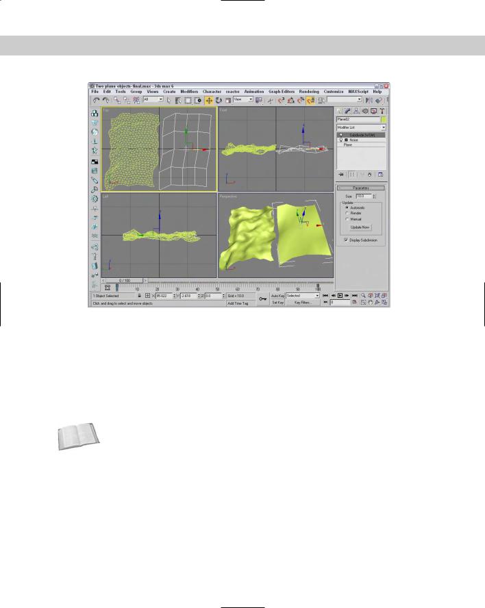
Figure 11-8 shows the difference between the World-Space modifier and the Object-Space modifier due to their order in the Modifier Stack. Although both objects receive the same modifiers, the World-Space modifier for the object on the right has to be applied after all other modifiers, so the object isn’t subdivided until after the Noise modifier has already been applied. Therefore, it doesn’t have the resolution to make a lot of bumps.
Cross- |
All Space Warps are also applied using World-Space coordinates, so they also have the WSM |
Reference |
letters next to their name. You can get more information on Space Warps in Chapter 38, |
|
|
|
“Using Space Warps.” |
Selection modifiers
The first set of modifiers available in the Modifiers menu is the Selection modifiers. You can use these modifiers to select subobjects for the various object types. You can then apply other modifiers to these subobject selections. Any modifiers that appear above a Selection modifier in the Modifier Stack are applied to the subobject selection.
Chapter 11 Introducing Modifiers for Basic Object Deformation |
309 |
Figure 11-8: The left Plane object has been subdivided before applying noise, and the right Plane has not.
Selection modifiers are available for every modeling type, including Mesh Select, Poly Select, Patch Select, Spline Select, Volume Select, FFD Select, and NURBS Surface Select. You can apply the Mesh Select, Poly Select, Patch Select, and Volume Select modifiers to any 3D object, but you can apply the Spline Select modifier only to spline and shape objects, the FFD Select modifier only to the FFD Space Warps objects, and the NURBS Surface Select modifier (found in the NURBS Editing submenu) only to NURBS objects. Any modifiers that appear above one of these Selection modifiers in the Modifier Stack are applied only to the selected subobjects.
Cross- Each of the Selection modifiers is covered for the various modeling types in its respective Reference chapter. For example, to learn about the Patch Select modifier, see Chapter 15, “Creating and
Editing Patches.”
When a Selection modifier is applied to an object, the transform buttons on the main toolbar become inactive. If you want to transform the subobject selection, you can do so with the XForm modifier.
310 Part II Working with Objects
New |
The Selection by Channel is a new addition to the Selection Modifiers set. You can learn |
Feature |
more about this modifier in Chapter 50, “Max and Games.” |
|
Volume Select modifier
Among the Selection modifiers, the Volume Select modifier is unique. It selects subobjects based on the area defined by the modifier’s gizmo. The Volume Select modifier selects all subobjects within the volume from a single object or from multiple objects.
In the Parameters rollout for the Volume Select modifier, shown in Figure 11-9, you can specify whether subobjects selected within a given volume should be Object, Vertex, or Face subobjects. Any new selection can Replace, be Added to, or be Subtracted from the current selection. You can use the Invert option to select the subobjects outside of the current volume. You can also choose either a Window or Crossing Selection Type.
Figure 11-9: The Volume Select parameters let you select using different shaped volumes.
The actual shape of the gizmo can be a Box, a Sphere, a Cylinder, or a Mesh Object. To use a Mesh Object, click the button beneath the Mesh Object option and then click the object to use in a viewport. In addition to selecting by a gizmo-defined volume, you can also select subobjects based on certain surface characteristics, such as Material IDs, Smoothing Groups, or a Texture Map including Mapping Channel or Vertex Color. This makes it possible to quickly select all vertices that have a Vertex Color assigned to them.
The Alignment options can Fit or Center the gizmo on the current subobject selection. The Reset button moves the gizmo to its original position and orientation, which typically is the bounding box of the object. The Auto Fit option automatically changes the size and orientation of the gizmo as the object it encompasses changes.
Note |
The Volume Select modifier also includes a Soft Selection rollout. Soft Selection lets you select |
|
adjacent subobjects to a lesser extent. The result is a smoother selection over a broader sur- |
|
face area. The Soft Selection options are explained in Chapter 12, “Modeling Basics.” |
Chapter 11 Introducing Modifiers for Basic Object Deformation |
311 |
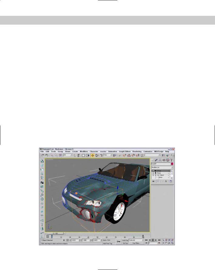
Tutorial: Applying damage to a car
In this tutorial, we use the Volume Select modifier to select the front corner of a car and then apply Noise and XForm modifiers to make the corner look like it’s been damaged in a collision.
To use modifiers to make a section of a car appear damaged, follow these steps:
1.Open the Damaged car.max file from the Chap 11 directory on the CD-ROM. This file includes a car model created by Viewpoint Datalabs.
2.With the front end of the car selected, choose the Modifiers Selection Modifiers Volume Select menu command.
This command applies the Volume Select modifier to the group.
3.In the Modifier Stack, click the plus sign icon to the left of the modifier name and select the Gizmo subobject. Move the gizmo in the Top viewport so only the front corner of the car is selected. In the Parameters rollout, select the Vertex option.
4.Choose the Modifiers Parametric Deformers Noise menu command to apply the Noise modifier to the selected volume. In the Parameters rollout, enable the Fractal option and set the X, Y, and Z Strength values to 30.
5.Choose Modifiers Parametric Deformers XForm to apply the XForm modifier and use its gizmo to push the selected area up and to the left in the Top viewport. This step makes the section look dented.
Figure 11-10 shows the resulting damaged car. Notice that the rest of the object is fine and only the selected volume area is damaged.
Figure 11-10: The Noise and XForm modifiers are applied to just the subobject selection.

312 Part II Working with Objects
Cross- |
You can see another example of how a Select modifier can be used to select and apply a |
Reference |
modifier to a subobject selection in Chapter 12, “Modeling Basics.” |
|
Parametric Deformer modifiers
Perhaps the most representative group of modifiers is the Parametric Deformers. These modifiers affect the geometry of objects by pulling, pushing, and stretching them. They all can be applied to any of the modeling types, including primitive objects.
Note In the upcoming examples, you might start to get sick of seeing the hammer model used over and over again, but using the same model enables you to more easily compare the effects of the various modifiers, and it’s more interesting to look at than a simple box.
Bend modifier
The Bend modifier can bend an object along any axis. Bend parameters include the Bend Angle and Direction, the Bend Axis, and the Limits. The Bend Angle defines the bend in the vertical direction, and the Direction value defines the bend in the horizontal direction.
Limit settings are the boundaries beyond which the modifier has no effect. You can set Upper and Lower Limits. Limits are useful if you want the modifier applied to only one half of the object. The Upper and Lower Limits are visible as a simple plane on the modifier gizmo. For example, if you want to bend a tall cylinder object and have the top half continue on straight, you could simply set an Upper Limit for the cylinder at the location where you want it to stay linear.
Note Several modifiers have the option to impose limits on the modifier, including upper and lower limit values.
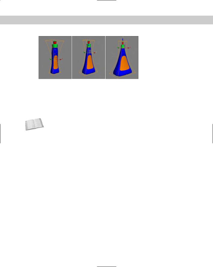
The hammer in Figure 11-11 shows several bending options. The left hammer shows a bend value of 75 degrees around the Z axis, the middle hammer also has a Direction value of 60, and the right hammer has an Upper Limit of 8.
Figure 11-11: The Bend modifier can bend objects about any axis.
Chapter 11 Introducing Modifiers for Basic Object Deformation |
313 |
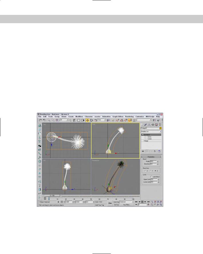
Tutorial: Bending a tree
If you have a tree model that you want to bend as if the wind were blowing, you can apply the Bend modifier. The tree then bends about its Pivot Point. Luckily, all the trees and plants found in the AEC Objects category have their Pivot Points set about their base, so bending a tree is really easy.
To bend a tree using the Bend modifier, follow these steps:
1.Select the Create AEC Objects Foliage menu command to access the available trees. Select a long thin tree like the Yucca, and click in the Top viewport to add it to the scene.
2.With the tree selected, select the Modifiers Parametric Deformers Bend menu command to apply the Bend modifier to the tree.
3.In the Parameters rollout found in the Modify panel, set the Bend Axis to Z and the Bend Angle to 60.
The tree bends as desired.
Figure 11-12 shows the bending Yucca plant. To animate this tree bending back and forth, just set keys for the Angle parameters.
Figure 11-12: The Bend modifier can be used to bend trees.
314 Part II Working with Objects
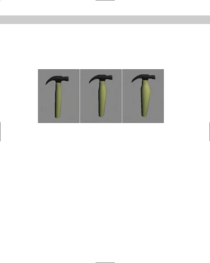
Taper modifier
The Taper modifier scales one end of an object. The end of the object that is scaled is the end opposite the Pivot Point. Taper parameters include the Amount and Curve, Primary and Effect Axes, and Limits. The Amount value defines the amount of taper applied to the affected end. The Curve value bends the taper inward (for negative values) or outward (for positive values). You can see the curve clearly if you look at the modifier’s gizmo. For example, you can create a simple vase or a bongo drum with the Taper modifier and a positive Curve value.
The Primary Axis defines the axis about which the taper is applied. The Effect axis can be a single axis or a plane, and the options change depending on your Primary Axis. This defines the axis or plane along which the object’s end is scaled. For example, if the Z axis is selected as the Primary Axis, then selecting the XY Effect plane scales the object equally along both the X and Y axes. Selecting the Y Effect axis scales the end only along the Y axis. You can also select a Symmetry option to taper both ends equally. Taper limits work just like the Bend modifier.
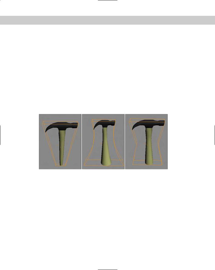
The left hammer in Figure 11-13 shows a taper of 1.0 about the Z axis, the middle hammer also has a Curve value of –2, and the right hammer has the Symmetry option selected.
Figure 11-13: The Taper modifier can proportionally scale one end of an object.
Tutorial: Creating a yo-yo
The Taper modifier can be used to create a variety of simple objects quickly, such as a yo-yo.
To create a yo-yo using the Taper modifier, follow these steps:
1.Select Create Standard Primitives Sphere, and drag in the Front viewport to create a sphere object.
2.With the sphere object selected, choose Modifiers Parametric Deformers Taper to apply the Taper modifier. Set the Taper Amount to 4.0 about the Primary Z Axis and XY as the Effect plane, and enable the Symmetry option.
Figure 11-14 shows the resulting yo-yo; just add a string.

Chapter 11 Introducing Modifiers for Basic Object Deformation |
315 |
Figure 11-14: The Taper modifier can be used to create a simple yo-yo.
Twist modifier
The Twist modifier deforms an object by rotating one end of an axis in one direction and the other end in the opposite direction. Twist parameters include Angle and Bias values, a Twist Axis, and Limits.
The Angle value is the amount of twist in degrees that is applied to the object. The Bias value cause the twists to bunch up near the Pivot Point (for negative values) or away from the Pivot Point (for positive values).
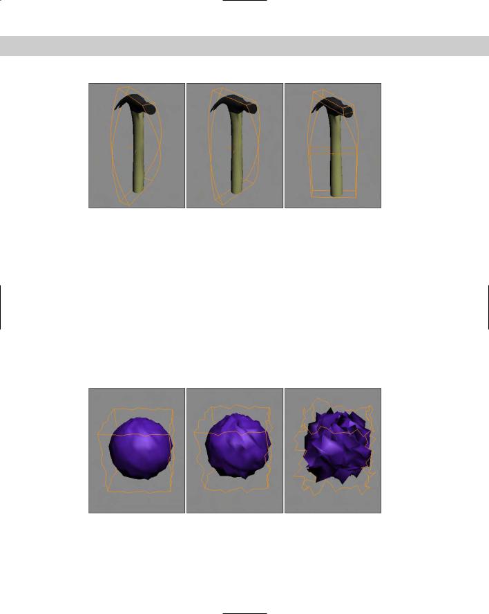
The left hammer in Figure 11-15 shows a twist angle of 120 about the Z axis, the middle hammer shows a Bias value of 20, and the right hammer has an Upper Limit value of 8.
Noise modifier
The Noise modifier randomly varies the position of object vertices in the direction of the selected axes. Noise parameters include Seed and Scale values, a Fractal option with Roughness and Iterations settings, Strength about each axis, and Animation settings.
The Seed value sets the randomness of the noise. If two identical objects have the same settings and the same Seed value, they look exactly the same even though a random noise has been applied to them. If you alter the Seed value for one of them, then they will look dramatically different.
316 Part II Working with Objects
Figure 11-15: The Twist modifiers can twist an object about an axis.
The Scale value determines the size of the position changes, so larger Scale values result in a smoother, less rough shape. The Fractal option enables fractal iterations, which result in more jagged surfaces. If Fractal is enabled, Roughness and Iterations become active. The Roughness value sets the amount of variation, and the Iterations value defines the number of times to complete the fractal computations. More iterations yield a wilder or chaotic surface, but require more computation time.
If the Animate Noise option is selected, the vertices positions will modulate for the duration of frames. The Frequency value determines how quickly the object’s noise changes, and the Phase setting determines where the noise wave starts and ends.
Figure 11-16 shows the Noise modifier applied to several sphere objects. These spheres make the Noise modifier easier to see than on the hammer object. The left sphere has Seed, Scale, and Strength values along all three axes set to 1.0, the middle sphere has increased the Strength values to 2.0, and the right sphere has enabled the Fractal option with a Roughness value of 1.0 and an Iterations value of 6.0.
Figure 11-16: The Noise modifier can apply a smooth or wild look to your objects.
Chapter 11 Introducing Modifiers for Basic Object Deformation |
317 |
Cross- |
Another solution for creating terrains is the Terrain compound object covered in Chapter 17, |
Reference |
“Building Compound Objects.” |
|
Stretch modifier
The Stretch modifier moves one axis in one direction while moving the other axes in the opposite direction, like pushing in on opposite sides of a balloon. Stretch parameters include Stretch and Amplify values, a Stretch Axis, and Limits.
The Stretch value equates the distance the object is pulled, and the Amplify value is a multiplier for the Stretch value. Positive values multiply the effect, and negative values reduce the stretch effect.
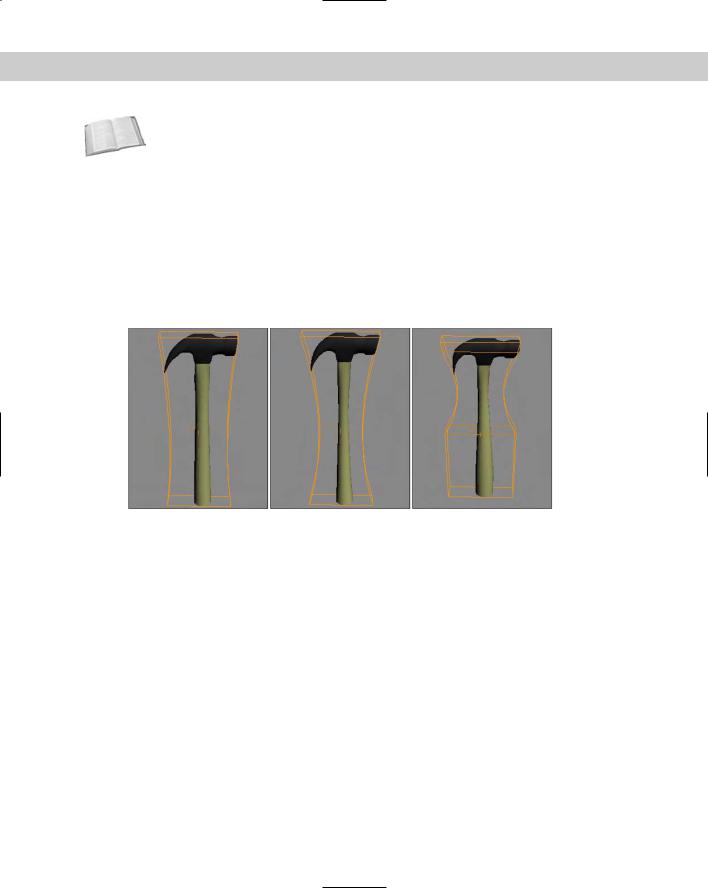
Figure 11-17 shows a Stretch value of 0.2 about the Z axis applied to the hammer, the middle hammer also has an Amplify value of 2.0, and the right hammer has an Upper Limit value of 8.
Figure 11-17: The Stretch modifier pulls along one axis while pushing the other two.
Squeeze modifier
The Squeeze modifier takes the points close to one axis and moves them away from the center of the object while it moves other points toward the center to create a bulging effect. Squeeze parameters include Amount and Curve values for Axial Bulge and Radial Squeeze, and Limits and Effect Balance settings.
The Effect Balance settings include a Bias value, which changes the object between the maximum Axial Bulge or the maximum Radial Squeeze. The Volume setting increases or decreases the volume of the object within the modifier’s gizmo.
Axial Bulge is enabled with an Amount value of 0.2 and a Curve value of 2.0 in the left hammer in Figure 11-18, the middle hammer has also added Radial Squeeze values of 0.4 and 2.0, and the right hammer has an Upper Limit value of 8.

318 Part II Working with Objects
Figure 11-18: The Squeeze modifier can bulge or squeeze along two different axes.
Push modifier
The Push modifier pushes an object’s vertices inward or outward as if they were being filled with air. The Push modifier also has one parameter: the Push Value. This value is the distance to move with respect to the object’s center.
The positive Push value pushes the vertices outward away from the center, and a negative Push value pulls the vertices in towards the center. The Push modifier can increase the size of characters or make an object thinner by pulling its vertices in. Figure 11-19 shows the hammer pushed with 0.05, 0.1, and 0.15 values.
Figure 11-19: The Push modifier can increase the volume of an object.
Relax modifier
The Relax modifier tends to smooth the overall geometry by separating vertices that lie closer than an average distance. Parameters include a Relax Value that is the percentage of the distance that the vertices move. Values can range between 1.0 and –1.0. A value of 0 has no effect on the object. Negative values have the opposite effect, causing an object to become tighter and more distorted.
Chapter 11 Introducing Modifiers for Basic Object Deformation |
319 |
Tip |
As you model, it is common for meshes to have sections that are too tight. The Relax modi- |
|
fier can be used to cause the areas that are too tight to be relaxed. Another common place |
|
to use the Relax modifier is to prepare surfaces for lighting using Radiosity. |
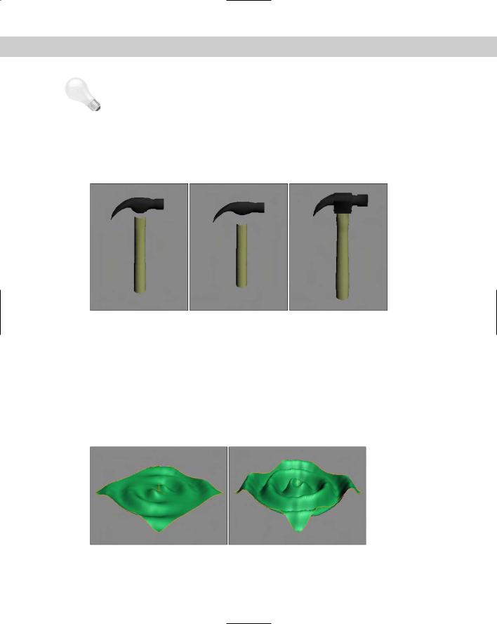
The Iterations value determines how many times this calculation is computed. The Keep Boundary Points Fixed option removes any points that are next to an open hole. Save Outer Corners maintains the vertex position of corners of an object. The left and middle hammers of Figure 11-20 have Relax values of 1.0 and Iteration values of 1 and 3. The right hammer has a Relax value of –1.0 and an Iteration value of 1.
Figure 11-20: The Relax modifier can simplify the number of vertices in an object.
Ripple modifier
The Ripple modifier creates ripples across the surface of an object. This modifier is best used on a single object; if several objects need a ripple effect, use the Ripple Space Warp. The ripple is applied via a gizmo that you can control. Parameters for this modifier include two Amplitude values and values for the Wave Length, Phase, and Decay of the ripple.
The two amplitude values cause an increase in the height of the ripples opposite one another. Figure 11-21 shows the Ripple modifier applied to a simple Quad Patch with values of 10 for Amplitude 1 and a Wave Length value of 50. The right Quad Patch also has an Amplitude 2 value of 20.
Figure 11-21: The Ripple modifier can make small waves appear over the surface of an object.
320 Part II Working with Objects
Wave modifier
The Wave modifier produces a wave-like effect across the surface of the object. All the parameters of the Wave Parameter are identical to the Ripple modifier parameters. The difference is that the waves produced by the Wave modifier are parallel, and they propagate in a straight line. Figure 11-22 shows the Wave modifier applied to a simple Quad Patch with values of 5
for Amplitude 1 and a Wave Length value of 50. The right Quad Patch also has an Amplitude 2 value of 20.
Figure 11-22: The Wave modifier produces parallel waves across the surface of an object.
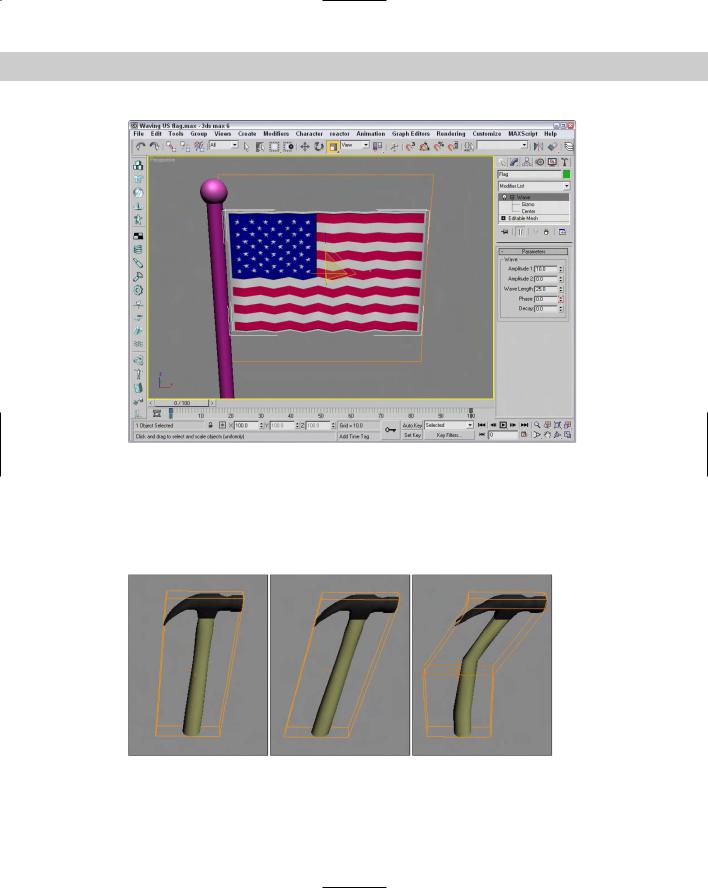
Tutorial: Waving a flag
The Wave modifier can add a gentle wave to an object such as a flag. If you animate the Phase value, you can show a flag unfurling in the breeze.
To animate a flag waving with the Wave modifier, follow these steps:
1.Open the Waving US flag.max file from the Chap 11 directory on the CD-ROM. This file includes a simple flag and flagpole made from primitive objects.
2.With the flag selected, select the Modifiers Parametric Deformers Wave menu command to apply the Wave modifier to the flag.
3.Notice how the waves run from the top of the flag to the bottom. You can change this by rotating the gizmo. Click the plus sign to the left of the Wave modifier in the Modifier Stack and select the Gizmo subobject. With the Select and Rotate tool (E), rotate the gizmo 90 degrees and then scale the gizmo with the Select and Scale tool (R) so it covers the flag object. Click the Gizmo subobject again to deselect gizmo suboject mode.
4.Set Amplitude 1 to 30, Amplitude 2 to 0, and the Wave Length to 25. Then click the Auto Key button (N), drag the Time Slider to frame 100, and set the Phase value to 4. Click the Auto Key button (N) again to exit key mode.
Figure 11-23 shows the waving flag.
Skew modifier
The Skew modifier changes the tilt of an object by moving its top portion while keeping the bottom half fixed. Skew parameters include Amount and Direction values, a Skew Axis, and Limits. Figure 11-24 shows the hammer with a Skew value of 2.0, the middle hammer has a Skew value of 5, and the right hammer has an Upper Limit of 8.
Chapter 11 Introducing Modifiers for Basic Object Deformation |
321 |
Figure 11-23: The Wave modifier can gently wave a flag.
Slice modifier
You can use the Slice modifier to divide an object into two separate objects. Applying the Slice modifier creates a Slice gizmo. This gizmo looks like a simple plane and can be transformed and positioned to define the slice location. To transform the gizmo, you need to select it from the Stack hierarchy.
Figure 11-24: You can use the Skew modifier to tilt objects.

322 Part II Working with Objects
Note |
You can use the Slice modifier to make objects slowly disappear a layer at a time. |
The Slice parameters include four slice type options. Refine Mesh simply adds new vertices and edges where the gizmo intersects the object. The Split Mesh option creates two separate objects. The Remove Top and Remove Bottom options delete all faces and vertices above or below the gizmo intersection plane.
Using Triangular or Polygonal faces, you can also specify whether the faces are divided. Figure 11-25 shows the top and bottom halves of a hammer object. The right hammer is sliced at an angle.
Figure 11-25: The Slice modifier can cut objects into two separate pieces.
Note |
Editable Meshes also have a Slice tool that can produce similar results. The difference is that |
|
the Slice modifier can work on any type of object, not only on meshes. |
Shell modifier
When a mesh subobject is deleted, it leaves a hole in the surface that allows the inside of the object to be seen. This inside section doesn’t have normals pointing the right direction, so the object appears blank unless the Force 2-Sided option in the Viewport Configuration dialog box is selected. The Shell modifier makes an object into a shell with a surface on the inside and outside of the object.
New |
The Shell modifier is new to 3ds max 6. |
Feature |
|
For the Shell modifier, you can specify Inner and Outer Amount values. This is the distance from the original position that the inner or outer surfaces are moved. These values together determine how thick the shell is. The Bevel Edges and Bevel Spline options let you bevel the edges of the shell. By clicking on the Bevel Spline button, you can select a spline to define the bevel shape.
For each Material ID, you can use the Material ID for the inner section or the outer section. The Auto Smooth Edge lets you smooth the edge for all edges that are within the Angle

Chapter 11 Introducing Modifiers for Basic Object Deformation |
323 |
threshold. The edges can also be mapped using the Edge Mapping options. The options include Copy, None, Strip, and Interpolate. The Copy option uses the same mapping as the original face, None assigns new mapping coordinates, Strip maps the edges as one complete strip, and Interpolate interpolates the mapping between the inner and outer mapping.
The last options make selecting the edges, the inner faces, or the outer faces easy. The Straighten Corners option moves the vertices so the edges are straight.
Tutorial: Making a Pacman-like character
A good example of how the Shell modifier can be used is to create a Pacman-like character from a sphere.
To use the Shell modifier to create a Pacman-like character, follow these steps:
1.Open the Pacman shell.max file from the Chap 11 directory on the CD-ROM. This file includes a simple sphere object that has had several faces deleted.
2.With the sphere object selected, select Modifiers Parametric Deformers Shell to apply the Shell modifier. Set the Outer Amount to 5.0.
This makes the hollow sphere into a thin shell. Notice that the lighting inside the sphere is now correct.
Figure 11-26 shows the resulting shell.
Figure 11-26: The Shell modifier can add an inside to hollow objects.
324 Part II Working with Objects
Spherify modifier
The Spherify modifier distorts an object into a spherical shape. The single Spherify parameter is the percent of the effect to apply. Figure 11-27 shows the hammer with Spherify values of 10, 20, and 30 percent.
The Spherify modifier is different from the Push modifier; it can apply a bulge effect to a specific area, while the Push modifier moves all vertices equally outward for the entire object.
Figure 11-27: The Spherify modifier pushes all vertices outward like a sphere.
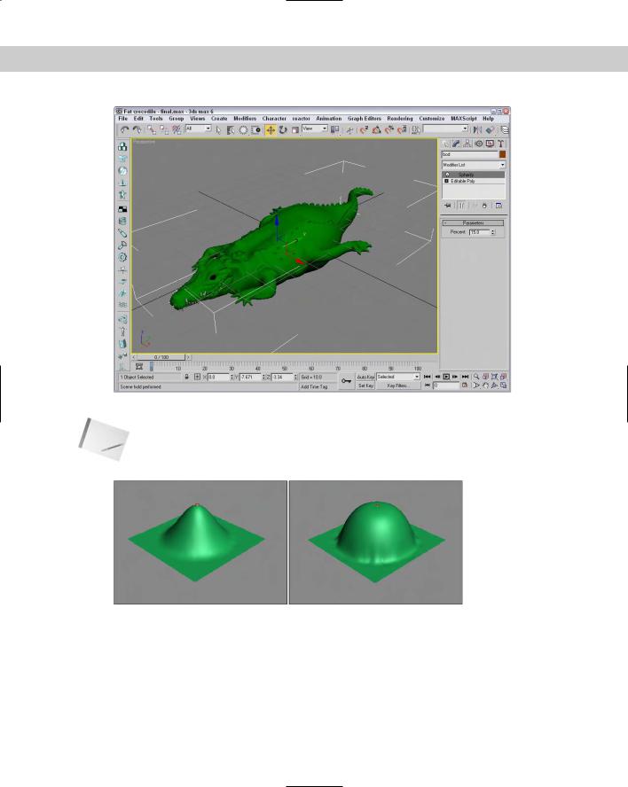
Tutorial: Making a fat crocodile
A good way to use the Spherify modifier is to add bulges to an object. For example, in this tutorial we make a plump crocodile even fatter by applying the Spherify modifier.
To fatten up a crocodile character with the Bend modifier, follow these steps:
1.Open the Fat crocodile.max file from the Chap 11 directory on the CD-ROM. This file includes a crocodile model created by Viewpoint Datalabs.
2.With the crocodile selected, select the Modifiers Parametric Deformers Spherify menu command to apply the Spherify modifier to the crocodile. The bulge appears around the object’s pivot point.
3.In the Parameters rollout, set the Percent value to 15.
Figure 11-28 shows the plump crocodile.
Affect Region modifier
The Affect Region modifier can cause a local surface region to bubble up or be indented. Affect Region parameters include Falloff, Pinch, and Bubble values. The Falloff value sets the size of the area that is affected. The Pinch value makes the region tall and thin, and the Bubble value rounds the affected region. You can also select the Ignore Back Facing option. Figure 11-29 shows the Affect Region modifier applied to a Quad Patch with a Falloff value of 80 on the left, and on the right with a Bubble value of 1.0. The height and direction of the region is determined by the position of the modifier gizmo, which is a line connected by two points.
Chapter 11 Introducing Modifiers for Basic Object Deformation |
325 |
Figure 11-28: The Spherify modifier can fatten up a crocodile.
Note The Affect Region modifier accomplishes the same effect as the Soft Selection feature, but Affect Region applies the effect as a modifier, making it easier to discard.
Figure 11-29: The Affect Region modifier can raise or lower the surface region of an object.
Lattice modifier
The Lattice modifier changes an object into a lattice by creating struts where all the edges are located or by replacing each joint with an object. The Lattice modifier considers all edges as struts and all vertices as joints.

326 Part II Working with Objects
The parameters for this modifier include several options to determine how to apply the effect. These options include the Entire Object, to Joints Only, to Struts Only, or Both (Struts and Joints). If the Apply to Entire Object option isn’t selected, then the modifier is applied to the current subobject.
For struts, you can specify Radius, Segments, Sides, and Material ID values. You can also specify to Ignore Hidden Edges, to create End Caps, and to Smooth the Struts.
For joints, you can select Tetra, Octa, or Icosa types with Radius, Segments, and Material ID values. There are also controls for Mapping Coordinates.
Note Although the joints settings enable you to select only one of three different types, you can use the Scatter compound object to place any type of object instead of the three defaults. To do this, apply the Lattice modifier and then select the Distribute Using All Vertices option in the Scatter Objects rollout.
Figure 11-30 shows the effect of the Lattice modifier. The left hammer has only joints applied, the middle hammer has only struts applied, and the right hammer has both applied.
Figure 11-30: The Lattice modifier divides an object into struts, joints, or both.
Mirror modifier
You can use the Mirror modifier to create a mirrored copy of an object or subobject. The Parameters rollout lets you pick a mirror axis or plane and an Offset value. The Copy option creates a copy of the mirrored object and retains the original selection.
Note The Mirror modifier works the same as the Mirror command found in the Tools menu, but the modifier is handy if you want to be able to quickly discard the mirroring changes.
Displace modifier
The Displace modifier offers two unique sets of features. It can alter an object’s geometry by displacing elements using a gizmo, or it can change the object’s surface using a grayscale bitmap image. The Displace gizmo can have one of four different shapes: Planar, Cylindrical, Spherical, or Shrink Wrap. This gizmo can be placed exterior to an object or inside an object to push it from the inside.

Chapter 11 Introducing Modifiers for Basic Object Deformation |
327 |
The Displace modifier parameters include Strength and Decay values. You can also specify the dimensions of the gizmo. A cylindrical-shaped gizmo can be capped or uncapped. The alignment parameters let you align the gizmo to the X, Y, or Z axes, or you can align it to the current view. The rest of the parameters deal with displacing the surface using a bitmap image. Figure 11-31 shows a Quad Patch with the Plane-shaped gizmo applied with a Strength value of 25. To the right is a Quad Patch with the Sphere-shaped gizmo.
Figure 11-31: You can use the Displace modifier’s gizmo as a modeling tool to change the surface of an object.
Cross-
Reference
The Displace modifier can also alter an object’s geometry using a grayscale bitmap image. This aspect of the modifier is covered in Chapter 22, “Adding Material Details with Maps.” In many ways, the Displace gizmo works like the Conform compound object. You can learn about the Conform compound object in Chapter 17, “Building Compound Objects.”
XForm modifier
The XForm modifier enables you to apply transforms such as Move, Rotate, and Scale to objects and/or subobjects. This modifier is applied by means of a gizmo that can be transformed using the transform buttons on the main toolbar. The XForm modifier has no parameters.
Note |
XForm is short for the word transform. |
Preserve modifier
The Preserve modifier works to maintain Edge Lengths, Face Angles, and Volume as an object is deformed and edited. Before an object is modified, make an additional copy. Then edit one of the copies. To apply the Preserve modifier, click the Pick Original button, then click the unmodified object, and finally, click the modified object. The object is modified to preserve the Edge Lengths, Face Angles, and Volume as defined in the Weight values. This helps prevent the topology of the modified object becoming too irregular.
The Iterations option determines the number of times the process is applied. You can also specify to apply to the Whole Mesh, to Selected Vertices Only, or to an Inverted Selection.
328 Part II Working with Objects
Free Form Deformer modifiers
The Free Form Deformers category of modifiers causes a lattice to appear around an object. This lattice is bound to the object, and you can alter the object’s surface by moving the lattice control points. Modifiers include FFD (Free Form Deformation) and FFD (Box/Cyl).
FFD (Free Form Deformation) modifier
The Free Form Deformation modifiers create a lattice of control points around the object. The object’s surface can deform the object when you move the control points. The object is deformed only if the object is within the volume of the FFD lattice. The three different resolutions of FFDs are 2×2, 3×3, and 4×4. The Set Number of Points button enables you to specify the number of points to be included in the FFD lattice.
You can also select to display the lattice or the source volume, or both. If the Lattice option is disabled, only the control points are visible. The Source Volume option shows the original lattice before any vertices were moved.
The two deform options are Only In Volume and All Vertices. The Only In Volume option limits the vertices that can be moved to the interior vertices only. If the All Vertices option is selected, the Falloff value determines the point at which vertices are no longer affected by the FFD. Falloff values can range between 0 and 1. The Tension and Continuity values control how tight the lines of the lattice are when moved.
The three buttons at the bottom of the FFD Parameters rollout help in the selection of control points. If the All X button is selected, then when a single control point is selected, all the adjacent control points along the X axis are also selected. This feature makes selecting an entire line of control points easier. The All Y and All Z buttons work in a similar manner in the other dimensions.
Use the Reset button to return the volume to its original shape if you make a mistake. The Conform to Shape button sets the offset of the Control Points with Inside Points, Outside Points, and Offset options.
To move the control points, select the Control Points subobject. This enables you to alter the control points individually.
FFD (Box/Cyl) modifier
The FFD (Box) and FFD (Cyl) modifiers can create a box-shaped or cylinder-shaped lattice of control points for deforming objects. Figure 11-32 shows how you can use the FFD modifier to distort the hammer by selecting the Control Point’s subobjects. The left hammer is distorted using a 2×2×2 FFD, the middle hammer has a 4×4×4 FFD, and the right hammer is surrounded with an FFD (Cyl) modifier.
Cross- |
The FFD (Box) and FFD (Cyl) lattices are also available as Space Warps. To learn more about |
Reference |
Space Warps, see Chapter 38, “Using Space Warps.” |
|

Chapter 11 Introducing Modifiers for Basic Object Deformation |
329 |
Figure 11-32: The FFD modifier changes the shape of an object by moving the lattice of Control Points that surround it.
Tutorial: Modeling a tire striking a curb
The FFD modifiers are great for changing the shape of soft-body object being struck by a solid object. Soft-body objects deform around the rigid object when they make contact. In this tutorial, we deform a tire that is hitting a curb.
To deform a tire striking a curb using an FFD modifier, follow these steps:
1.Open the Tire hitting a curb.max file from the Chap 11 directory on the CD-ROM. This file includes a simple tube object and a curb.
2.With the tire selected, choose Modifiers Free Form Deformers FFD 3×3×3 menu option.
A lattice gizmo appears around the tire.
3.Click the FFD name in the Modifier Stack, and select the Control Points subobject from the hierarchy list. Then select all the center control points in the Left viewport and scale the control points outward with the Select and Scale tool (R) to add some roundness to the tire.
4.Then select all the control points in the lower-left corner of the Front viewport and move these points diagonally up and to the right until the tire’s edge lines up with the curb.
Figure 11-33 shows the tire as it strikes the hard curb.