Добавил:
Опубликованный материал нарушает ваши авторские права? Сообщите нам.
Вуз: Предмет: Файл:
3ds Max 6 Bible (2004).pdf
Скачиваний:
55
Добавлен:
17.08.2013
Размер:
50.02 Mб
Скачать

Chapter 10 Transforming Objects—Translate, Rotate, and Scale

295

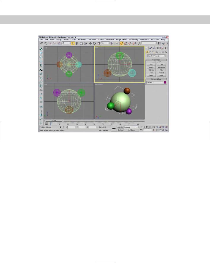
Figure 10-19: A methane molecule lattice drawn with the help of the Snap feature

Summary

Transforming objects in Max is one of the fundamental actions you can perform. The three basic ways to transform objects are moving, rotating, and scaling. Max includes many helpful features to enable these transformations to take place quickly and easily. In this chapter, we covered many of these features, including

Using the Move, Rotate, and Scale buttons and the Transform Gizmos

Transforming objects precisely with the Transform Type-In dialog box and status bar fields

Using Transform Managers to change coordinate systems and lock axes

Aligning objects with the Align dialog box, aligning normals, and aligning to views

Manipulating pivot points

Working with grids

Setting up snap points

Snapping objects to snap points

In the next chapter, we investigate the features in the Modify panel that enable you to modify objects with modifiers.


Introducing Modifiers for Basic Object Deformation

Think for a moment of a wood shop with all its various (and expensive) tools and machines. Some tools are simple like a screwdriver

or a sander, and others like a planer or router are more complex, but they all change the wood (or models) in different ways. In some ways, you can think of modifiers as these tools and machines that work on 3D objects.

Each woodshop tool has different parameters that control how it works, such as how hard you turn the screwdriver or the coarseness of the sandpaper. Likewise, each modifier has parameters that you can set that determine how it affects the 3D object.

Modifiers can be used in a number of different ways, to reshape objects, apply material mappings, deform an object’s surface, and perform many other actions. Many different types of modifiers exist. This chapter introduces you to the concept of modifiers and explains the basics on how to use them. I also cover a specific category of modifiers, Parametric Deformers.

Exploring the Modifier Stack

All modifiers that are applied to an object are listed together in a single location known as the Modifier Stack. This Stack is the manager for all modifiers applied to an object and can be found at the top of the Modify panel in the Command Panel. You can also use the Stack to apply and delete modifiers; cut, copy, and paste modifiers between objects; and reorder them.

Understanding Base Objects

11C H A P T E R

In This Chapter

Using the Modifier Stack to manage modifiers

Learning to work with modifier gizmos

Exploring the Select modifiers

Deforming objects with the Parametric Deformer and FFD modifiers

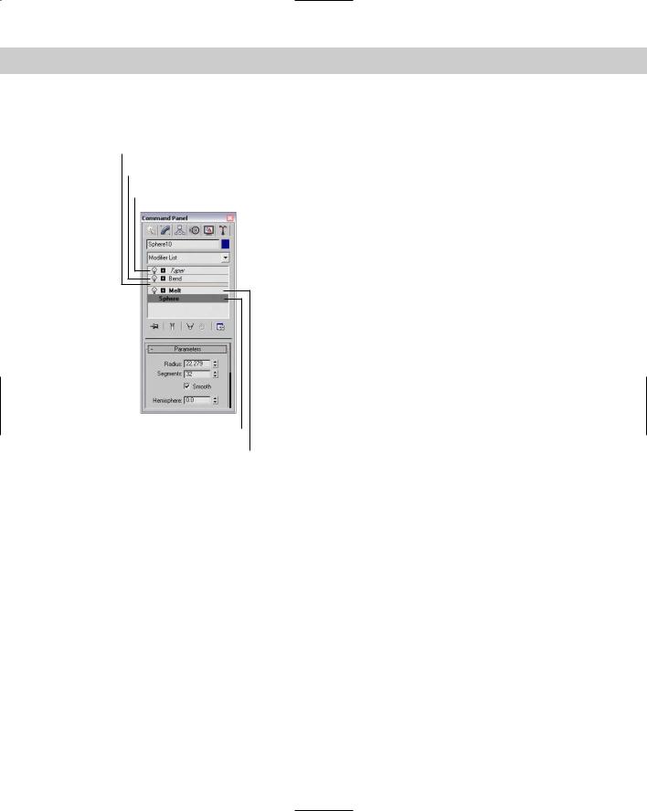
The first entry in the Modifier Stack isn’t a modifier at all; it is the Base Object. The Base Object is the original object type. The Base Object

298 Part II Working with Objects

for a primitive is listed as its object type, such as Sphere or Torus. Editable meshes, polys, patches, and splines can also be Base Objects. NURBS Surfaces and NURBS Curves are also Base Object types.

You can also see the Base Objects using the Schematic View window if you enable the Base Objects option in the Display floater.

Applying modifiers

An object can have several modifiers applied to it. Modifiers can be applied using the Modifiers menu or by selecting the modifier from the Modifier List drop-down list located at the top of the Modify panel directly under the object name. Selecting a modifier in the Modifiers menu or from the Modifier List applies the modifier to the current selected object. Modifiers can be applied to multiple objects if several objects are selected.

Note Some modifiers aren’t available for some types of objects. For example, the Extrude and Lathe modifiers are enabled only when a spline shape is selected.


Other Modifier Stack entities


Most modifiers are Object-Space modifiers, but another category called World-Space modi-


fiers also exists. World-Space modifiers are similar to Object-Space modifiers, except they are


applied using a global coordinate system instead of coordinate system that is local to the


object. More on World-Space modifiers is presented later in this chapter, but you should be


aware that World-Space modifiers (identified with the initials, WSM) appear at the top of the


Modifier Stack and are applied to the object after all Object-Space modifiers.


In addition to World-Space modifiers, Space Warp bindings also appear at the top of the


Modifier Stack.

Cross-

Space Warps are covered in Chapter 38, “Using Space Warps.”

Reference


Using the Modifier Stack


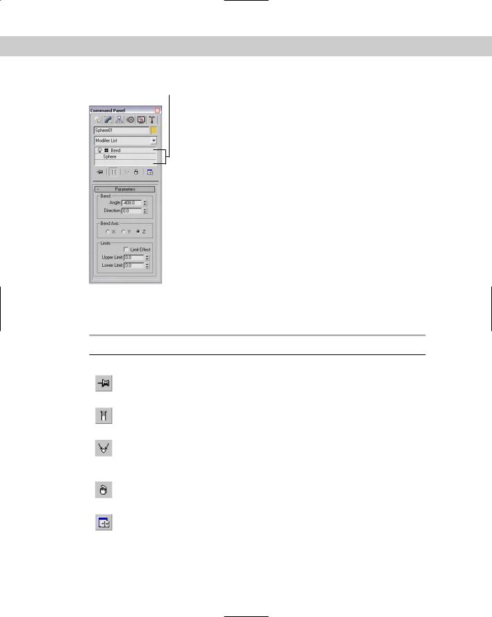
After a modifier is applied, its parameters appear in rollouts within the Command Panel. The


Modifier Stack rollout, shown in Figure 11-1, lists the base object and all the modifiers that


have been applied to an object. Any new modifiers applied to an object are placed at the top


of the stack. By selecting a modifier from the list in the Modifier Stack, all the parameters for


that specific modifier are displayed in rollouts.

Tip

You can increase or decrease the size of the Modifier Stack by dragging the horizontal bar


that is beneath the Modifier Stack buttons.

Chapter 11 Introducing Modifiers for Basic Object Deformation

299

Modifier Stack

Figure 11-1: The Modifier Stack rollout displays all modifiers applied to an object.

Beneath the Modifier Stack are five buttons that affect the selected modifier. They are as described in Table 11-1.

Table 11-1: Modifier Stack Buttons

Button Name

Description


Pin Stack

Makes the parameters for the selected modifier available for editing even


if another object is selected (like taking a physical pin and sticking it into


the screen so it won’t move).

Show End Result

Shows the end results of all the modifiers in the entire Stack when

On/Off Toggle

enabled and only the modifiers up to the current selected modifier if


disabled.

Make Unique

Used to break any instance or reference links to the selected object. After


you click this button, an object will no longer be modified along with the


other objects for which it was an instance or reference. Works for Base


Object and modifiers.

Remove Modifier

Used to delete a modifier from the Stack or unbind a Space Warp if one

from the Stack

is selected. Deleting a modifier restores it to its same state that it was in


before the modifier was applied.

Configure

Opens a pop-up menu where you can select to show a set of modifiers as

Modifier Sets

buttons above the Modifier Stack. You can also select which modifier set


appears at the top of the list of modifiers. The pop-up menu also includes


an option to configure and define the various sets of modifiers.


300 Part II Working with Objects

Cross-

For more information on configuring modifier sets, see Chapter 4, “Customizing the Max

Reference

Interface and Setting Preferences.”


If you right-click on a modifier, a pop-up menu appears. This pop-up menu includes commands to rename the selected modifier, which you might want to do if the same modifier is applied to the same object multiple times. This pop-up menu also includes an option to delete the selected modifier.

Copying and pasting modifiers

The pop-up menu also includes options to Cut, Copy, Paste, and Paste Instance modifiers. The Cut command deletes the modifier from the current object but makes it available for pasting onto other objects. The Copy command retains the modifier for the current object and makes it available to paste onto another object. After you use the Cut or Copy command, you can use the Paste command to apply the modifier to another object. The Paste Instance command retains a link between the original modifier and the instanced modifier, so that any changes to either modifier affect the other instances.

You can also apply modifiers for the current object onto other objects by dragging the modifier from the Modifier Stack and dropping it on the other object in a viewport. Holding down the Ctrl key while dropping a modifier onto an object in a viewport applies the modifier as an instance (like the Paste Instance command). Holding down the Shift key while dragging and dropping a modifier on an object in the viewport removes the modifier from the current modifier and applies it to the object on which it is dropped (like the Cut and Paste commands).

Cross-

You can also cut, copy, and paste modifiers using the Schematic View window. See Chapter

Reference

9, “Working with the Schematic View,” for more details.


Using instanced modifiers

When you apply a single modifier to several objects at the same time, the modifier shows up in the Modifier Stack for each object. These are instanced modifiers that maintain a connection to each other. If any of these instanced modifiers is changed, the change is propagated to all other instances. This feature is very helpful for modifying large groups of objects.

When a modifier is copied between different objects, you can select to make the copy an instance.

To see all the objects that are linked to a particular modifier, select an object in the viewport and choose Views Show Dependencies. All objects with instanced modifiers that are connected to the current selection appear in bright pink. At any time, you can break the link between a particular instanced modifier and the rest of the objects using the Make Unique button in the Modifier Stack rollout.

Identifying instances and references in the Modifier Stack

If you look closely at the Modifier Stack, you will notice that it includes some visual clues that help you identify instances and references. Normal object and modifier copies appear in normal text, but instances appear in bold. This applies to both objects and modifiers. If a modifier is applied to two or more objects, then it appears in italic.

Referenced objects and modifiers can be identified by a Reference Object Bar that splits the Modifier Stack into two categories — ones that are unique to the referenced object (above the bar) and ones that shared with the other references (below the bar).

Chapter 11 Introducing Modifiers for Basic Object Deformation

301

Figure 11-2 shows each of these cases in the Modifier Stack.

Reference Object Bar

Referenced modifier

Referenced modifier applied to two or more objects

Instanced object

Instanced modifier

Figure 11-2: The Modifier Stack changes the text style to identify instances and references.

Disabling and removing modifiers

Clicking the light bulb icon to the left of the modifier name toggles the modifier on and off. The right-click pop-up menu also offers options to turn the modifier off in the viewport or off for the renderer.

To remove a modifier from the Modifier Stack, just select the modifier and press the Remove Modifier button below the stack. This button removes the selected modifier only. You can select multiple modifiers at once by holding down the Ctrl key while clicking individually on the modifiers, or by holding down the Shift key and clicking on the first and last modifiers in a range.

Reordering the Stack

Modifiers are listed in the Modifier Stack with the first applied ones on the bottom and the newest applied ones on the top. The Stack order is important and can change the appearance of the object. Max applies the modifiers starting with the lowest one in the Stack first and the topmost modifier last. You can change the order of the modifiers in the Stack by selecting a modifier and dragging it above or below the other modifiers. You cannot drag it below the object type or above any World-Space modifiers or Space Warp bindings.

302 Part II Working with Objects

Tutorial: Creating a Molecular Chain

Whether you’re working with DNA splices or creating an animation to show how molecular chains are formed, you can use the Lattice and Twist modifiers to quickly create a molecular chain. Using these chains shows how reordering the Modifier Stack can change the outcome.

To create a molecular chain using modifiers, follow these steps.

1.Select Create Standard Primitives Plane and drag in the Top viewport to create a Plane object. Set its Length to 300, its Width to 60, its Length Segments to 11, and its Width Segments to 1.

2.With the Plane object selected, select Modifiers Parametric Deformers Lattice to apply the Lattice modifier. Enable the Apply to Entire Object option. Then set the Struts Radius value to 1.0 with 12 sides and the Joints Base Type to Icosa with a Radius of 6.0 and a Segments value of 6.

3.Select Modifiers Parametric Deformers Twist and set the Twist Angle to 360.

4.Notice that the Sphere objects have been twisted along with the Plane object. You can fix this by switching the modifier order in the Modifier Stack. Select the Lattice modifier and drag and drop it above the Twist modifier in the stack. This step corrects the elongated spheres.

Figure 11-3 shows the corrected molecular chain.

Figure 11-3: Changing the order of the modifiers in the Stack can affect the end result.

Chapter 11 Introducing Modifiers for Basic Object Deformation

303

Holding and fetching a scene

Before going any farther, you need to know about an important feature in Max that allows you to set a stopping point for the current scene. The Hold command saves the scene into a temporary buffer for easy recovery. After a scene is set with the Hold command (Alt+Ctrl+H), you can bring it back instantly with the Fetch command (Alt+Ctrl+F). These commands provide a quick way to backtrack on modifications to a scene or project without your having to save and reload the project. If you use these commands before applying or deleting modifiers, you can save some potential headaches.

Tip Along with saving your file often, using the Hold command before applying any complex modifier to an object is a good idea.

Collapsing the Stack

Collapsing the Stack removes all its modifiers by permanently applying them to the object. It also resets the modification history back to a baseline. All the individual modifiers in the

Stack are combined into one single modification. This feature eliminates the ability to change any modifier parameters, but it simplifies the object and conserves memory. The right-click pop-up menu offers options to Collapse To and Collapse All. You can collapse the entire Stack with the Collapse All command, or you can collapse to the current selected modifier with the Collapse To command. Collapsed objects typically become Editable Mesh objects.

When you apply a collapse command, a warning dialog box appears, shown in Figure 11-4, notifying you that this action will delete all the creation parameters. Click Yes to continue with the collapse.

Note In addition to the Yes and No buttons, the warning dialog box includes a Hold/Yes button. This button saves the current state of the object to the Hold buffer and then applies the Collapse All function. If you have any problems, you can retrieve the object’s previous state before the collapse was applied by choosing Edit Fetch (Alt+Ctrl+F).

Figure 11-4: Because the Collapse operation cannot be undone, this warning dialog box offers a chance to Hold the scene.

Using the Collapse utility

You can also use the Collapse utility found on the Utility panel to collapse the Modifier Stack. This utility enables you to collapse an object or several objects to a Modifier Stack Result or to a Mesh object. Collapsing to a Modifier Stack Result doesn’t necessarily produce a mesh

304 Part II Working with Objects

but collapses the object to its base object state, which is displayed at the bottom of the Stack hierarchy. Depending on the Stack, this could result in a mesh, patch, spline, or other object type. You can also collapse to a Single Object or to Multiple Objects. Figure 11-5 shows the rollout for the Collapse utility.

Figure 11-5: The Collapse utility can collapse several objects at once.

If the Mesh and Single Object options are selected, you can also select to perform a Boolean operation. The Boolean operations are available if you are collapsing several overlapping objects into one. The options are Union (which combines geometries together), Intersection (which combines only the overlapping geometries), and Subtraction (which subtracts one geometry from another).

Cross-

Boolean operations can also be performed using the Boolean compound object. See

Reference

Chapter 17, “Building Compound Objects,” for details on this object type.


If multiple objects are selected, then a Boolean Intersection results in only the sections of the objects that are intersected by all objects; if none of the objects overlap, all objects disappear.

If you use the Boolean Subtraction option, you can specify which object is the base object that the other objects are subtracted from by selecting that object first and then selecting the other objects by holding down the Ctrl key and clicking them. Figure 11-6 shows an example of each of the Boolean operations.

Using gizmo subobjects

As you’ve worked with modifiers, you’ve probably noticed the orange wire-frame box that surrounds the object in the viewports when you apply the modifier. These boxes are

called modifier gizmos, and they provide a visual control for how the modifier changes the geometry. If you want, you can work directly with these gizmos to affect the modifier.

Chapter 11 Introducing Modifiers for Basic Object Deformation

305

Figure 11-6: Using the Collapse utility, you can select the following Boolean operations (shown from left to right): Union, Intersection, and Subtraction.

Clicking the plus sign to the left of the modifier name reveals any subobjects associated with the modifier. To select the modifier subobjects, simply click the subobject name. The subobject name is highlighted in yellow when selected. Many modifiers create gizmo subobjects. Gizmos have a center and can be transformed and controlled like regular objects using the transformation buttons on the main toolbar. Another common modifier subobject is Center, which controls the point about which the gizmo is transformed.

Tutorial: Squeezing a plastic bottle

To get a feel for how the modifier gizmo and its center affect an object, this tutorial applies the Squeeze modifier to a plastic bottle; by moving its center, we can change the shape of the object.

To change a modifier’s characteristics by moving its center, follow these steps:

1.Open the Plastic bottle.max file from the Chap 11 directory on the CD-ROM.

This file includes a plastic squirt bottle with all the parts attached into a single mesh object.

2.With the bottle selected, choose the Modifiers Parametric Deformers Squeeze menu command to apply the Squeeze modifier to the bottle. Set the Radial Squeeze Amount value to 1.

3.In the Modifier Stack, click the plus sign to the left of the Squeeze modifier to see the modifier’s subobjects. Select the Center subobject.

The selected subobject is highlighted in yellow.

4.Click the Select and Move (W) button on the main toolbar, and drag the center point in the Perspective viewport upward.

Notice how the bottle’s shape changes.

Figure 11-7 shows several different bottle shapes created by moving the modifier’s center point.