

- •Preface
- •About This Book
- •Acknowledgments
- •Contents at a Glance
- •Contents
- •Relaxing at the Beach
- •Dressing the Scene
- •Animating Motion
- •Rendering the Final Animation
- •Summary
- •The Interface Elements
- •Using the Menus
- •Using the Toolbars
- •Using the Viewports
- •Using the Command Panel
- •Using the Lower Interface Bar Controls
- •Interacting with the Interface
- •Getting Help
- •Summary
- •Understanding 3D Space
- •Using the Viewport Navigation Controls
- •Configuring the Viewports
- •Working with Viewport Backgrounds
- •Summary
- •Working with Max Scene Files
- •Setting File Preferences
- •Importing and Exporting
- •Referencing External Objects
- •Using the File Utilities
- •Accessing File Information
- •Summary
- •Customizing Modify and Utility Panel Buttons
- •Working with Custom Interfaces
- •Configuring Paths
- •Selecting System Units
- •Setting Preferences
- •Summary
- •Creating Primitive Objects
- •Exploring the Primitive Object Types
- •Summary
- •Selecting Objects
- •Setting Object Properties
- •Hiding and Freezing Objects
- •Using Layers
- •Summary
- •Cloning Objects
- •Understanding Cloning Options
- •Mirroring Objects
- •Cloning over Time
- •Spacing Cloned Objects
- •Creating Arrays of Objects
- •Summary
- •Working with Groups
- •Building Assemblies
- •Building Links between Objects
- •Displaying Links and Hierarchies
- •Working with Linked Objects
- •Summary
- •Using the Schematic View Window
- •Working with Hierarchies
- •Setting Schematic View Preferences
- •Using List Views
- •Summary
- •Working with the Transformation Tools
- •Using Pivot Points
- •Using the Align Commands
- •Using Grids
- •Using Snap Options
- •Summary
- •Exploring the Modifier Stack
- •Exploring Modifier Types
- •Summary
- •Exploring the Modeling Types
- •Working with Subobjects
- •Modeling Helpers
- •Summary
- •Drawing in 2D
- •Editing Splines
- •Using Spline Modifiers
- •Summary
- •Creating Editable Mesh and Poly Objects
- •Editing Mesh Objects
- •Editing Poly Objects
- •Using Mesh Editing Modifiers
- •Summary
- •Introducing Patch Grids
- •Editing Patches
- •Using Modifiers on Patch Objects
- •Summary
- •Creating NURBS Curves and Surfaces
- •Editing NURBS
- •Working with NURBS
- •Summary
- •Morphing Objects
- •Creating Conform Objects
- •Creating a ShapeMerge Object
- •Creating a Terrain Object
- •Using the Mesher Object
- •Working with BlobMesh Objects
- •Creating a Scatter Object
- •Creating Connect Objects
- •Modeling with Boolean Objects
- •Creating a Loft Object
- •Summary
- •Understanding the Various Particle Systems
- •Creating a Particle System
- •Using the Spray and Snow Particle Systems
- •Using the Super Spray Particle System
- •Using the Blizzard Particle System
- •Using the PArray Particle System
- •Using the PCloud Particle System
- •Using Particle System Maps
- •Controlling Particles with Particle Flow
- •Summary
- •Understanding Material Properties
- •Working with the Material Editor
- •Using the Material/Map Browser
- •Using the Material/Map Navigator
- •Summary
- •Using the Standard Material
- •Using Shading Types
- •Accessing Other Parameters
- •Using External Tools
- •Summary
- •Using Compound Materials
- •Using Raytrace Materials
- •Using the Matte/Shadow Material
- •Using the DirectX 9 Shader
- •Applying Multiple Materials
- •Material Modifiers
- •Summary
- •Understanding Maps
- •Understanding Material Map Types
- •Using the Maps Rollout
- •Using the Map Path Utility
- •Using Map Instances
- •Summary
- •Mapping Modifiers
- •Using the Unwrap UVW modifier
- •Summary
- •Working with Cameras
- •Setting Camera Parameters
- •Summary
- •Using the Camera Tracker Utility
- •Summary
- •Using Multi-Pass Cameras
- •Creating Multi-Pass Camera Effects
- •Summary
- •Understanding the Basics of Lighting
- •Getting to Know the Light Types
- •Creating and Positioning Light Objects
- •Viewing a Scene from a Light
- •Altering Light Parameters
- •Working with Photometric Lights
- •Using the Sunlight and Daylight Systems
- •Using Volume Lights
- •Summary
- •Selecting Advanced Lighting
- •Using Local Advanced Lighting Settings
- •Tutorial: Excluding objects from light tracing
- •Summary
- •Understanding Radiosity
- •Using Local and Global Advanced Lighting Settings
- •Working with Advanced Lighting Materials
- •Using Lighting Analysis
- •Summary
- •Using the Time Controls
- •Working with Keys
- •Using the Track Bar
- •Viewing and Editing Key Values
- •Using the Motion Panel
- •Using Ghosting
- •Animating Objects
- •Working with Previews
- •Wiring Parameters
- •Animation Modifiers
- •Summary
- •Understanding Controller Types
- •Assigning Controllers
- •Setting Default Controllers
- •Examining the Various Controllers
- •Summary
- •Working with Expressions in Spinners
- •Understanding the Expression Controller Interface
- •Understanding Expression Elements
- •Using Expression Controllers
- •Summary
- •Learning the Track View Interface
- •Working with Keys
- •Editing Time
- •Editing Curves
- •Filtering Tracks
- •Working with Controllers
- •Synchronizing to a Sound Track
- •Summary
- •Understanding Your Character
- •Building Bodies
- •Summary
- •Building a Bones System
- •Using the Bone Tools
- •Using the Skin Modifier
- •Summary
- •Creating Characters
- •Working with Characters
- •Using Character Animation Techniques
- •Summary
- •Forward versus Inverse Kinematics
- •Creating an Inverse Kinematics System
- •Using the Various Inverse Kinematics Methods
- •Summary
- •Creating and Binding Space Warps
- •Understanding Space Warp Types
- •Combining Particle Systems with Space Warps
- •Summary
- •Understanding Dynamics
- •Using Dynamic Objects
- •Defining Dynamic Material Properties
- •Using Dynamic Space Warps
- •Using the Dynamics Utility
- •Using the Flex Modifier
- •Summary
- •Using reactor
- •Using reactor Collections
- •Creating reactor Objects
- •Calculating and Previewing a Simulation
- •Constraining Objects
- •reactor Troubleshooting
- •Summary
- •Understanding the Max Renderers
- •Previewing with ActiveShade
- •Render Parameters
- •Rendering Preferences
- •Creating VUE Files
- •Using the Rendered Frame Window
- •Using the RAM Player
- •Reviewing the Render Types
- •Using Command-Line Rendering
- •Creating Panoramic Images
- •Getting Printer Help
- •Creating an Environment
- •Summary
- •Creating Atmospheric Effects
- •Using the Fire Effect
- •Using the Fog Effect
- •Summary
- •Using Render Elements
- •Adding Render Effects
- •Creating Lens Effects
- •Using Other Render Effects
- •Summary
- •Using Raytrace Materials
- •Using a Raytrace Map
- •Enabling mental ray
- •Summary
- •Understanding Network Rendering
- •Network Requirements
- •Setting up a Network Rendering System
- •Starting the Network Rendering System
- •Configuring the Network Manager and Servers
- •Logging Errors
- •Using the Monitor
- •Setting up Batch Rendering
- •Summary
- •Compositing with Photoshop
- •Video Editing with Premiere
- •Video Compositing with After Effects
- •Introducing Combustion
- •Using Other Compositing Solutions
- •Summary
- •Completing Post-Production with the Video Post Interface
- •Working with Sequences
- •Adding and Editing Events
- •Working with Ranges
- •Working with Lens Effects Filters
- •Summary
- •What Is MAXScript?
- •MAXScript Tools
- •Setting MAXScript Preferences
- •Types of Scripts
- •Writing Your Own MAXScripts
- •Learning the Visual MAXScript Editor Interface
- •Laying Out a Rollout
- •Summary
- •Working with Plug-Ins
- •Locating Plug-Ins
- •Summary
- •Low-Res Modeling
- •Using Channels
- •Using Vertex Colors
- •Rendering to a Texture
- •Summary
- •Max and Architecture
- •Using AEC Objects
- •Using Architectural materials
- •Summary
- •Tutorial: Creating Icy Geometry with BlobMesh
- •Tutorial: Using Caustic Photons to Create a Disco Ball
- •Summary
- •mental ray Rendering System
- •Particle Flow
- •reactor 2.0
- •Schematic View
- •BlobMesh
- •Spline and Patch Features
- •Import and Export
- •Shell Modifier
- •Vertex Paint and Channel Info
- •Architectural Primitives and Materials
- •Minor Improvements
- •Choosing an Operating System
- •Hardware Requirements
- •Installing 3ds max 6
- •Authorizing the Software
- •Setting the Display Driver
- •Updating Max
- •Moving Max to Another Computer
- •Using Keyboard Shortcuts
- •Using the Hotkey Map
- •Main Interface Shortcuts
- •Dialog Box Shortcuts
- •Miscellaneous Shortcuts
- •System Requirements
- •Using the CDs with Windows
- •What’s on the CDs
- •Troubleshooting
- •Index
Chapter 16 Working with NURBS 457
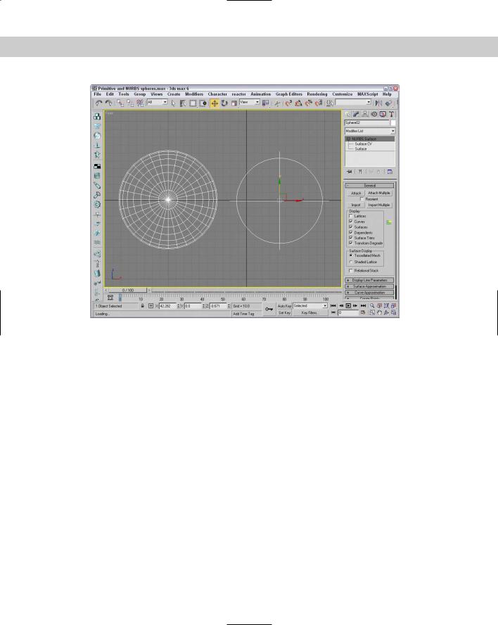
Figure 16-3: Standard primitives, like the sphere on the left, can be converted to NURBS surfaces.
Editing NURBS
You can edit and model NURBS curves and surfaces into desired shapes using the rollouts in the Modify panel, using the tools in the NURBS Creation Toolbox, or by working with the NURBS subobjects.
Attach and Import
When a NURBS curve or surface is selected, the General rollout includes buttons to attach and import NURBS. The Attach Multiple and Import Multiple buttons let you select from a dialog box several objects to attach or import. When attaching NURBS, you have the option of reorienting the attached object.
Display options
The General rollout, shown in Figure 16-4, also includes a Display section where you can select which elements get displayed. For curves, the options include Lattices, Curves, and Dependents. For surfaces, you have further options to display Surfaces, Surface Trims, and Transform Degrade, and you can also choose the surface display to be a Tessellated Mesh or

458 Part III Modeling
a Shaded Lattice. Next to the Display section is the NURBS Creation Toolbox button. This button opens a floating window of buttons that make working with NURBS easy. You find out more about the NURBS Creation Toolbox buttons in the next section.
For NURBS surfaces, the Display Line Parameters rollout lets you specify the number of U and V isoparms to use to display the NURBS surface. These isoparms are the lines that make the NURBS object visible in the viewport. You can also select to display Iso Only, Iso and Mesh, or Mesh Only.
Caution |
You can set the number of U and V Isoparms to 0, which makes the NURBS surface invisible. |
Figure 16-4: The General rollout includes options for determining what is displayed in the viewports.
NURBS
Creation
Toolbox
Surface and Curve Approximation
Using the Curve Approximation rollout, which becomes available when you choose the CV Curve option, you can set the Interpolation Steps value. The Optimize and Adaptive options automatically reduce the number of points required for the curve.
When you’re working with NURBS surfaces, the Surface Approximation rollout lets you control the surface details for both the viewport and the renderer. For Base Surface, Surface Edge, and Displaced Surface, you can set the Tessellation Method. The three Tessellation Presets are Low, Medium, and High. These presets set the parameters for the various tessellation
Chapter 16 Working with NURBS 459
methods, with Low representing the values that produce the lowest-quality surface. You can also select which tessellation method to use — Regular, Parametric, Spatial, Curvature, or Spatial and Curvature. Each of these methods uses a different algorithm to compute the surface.
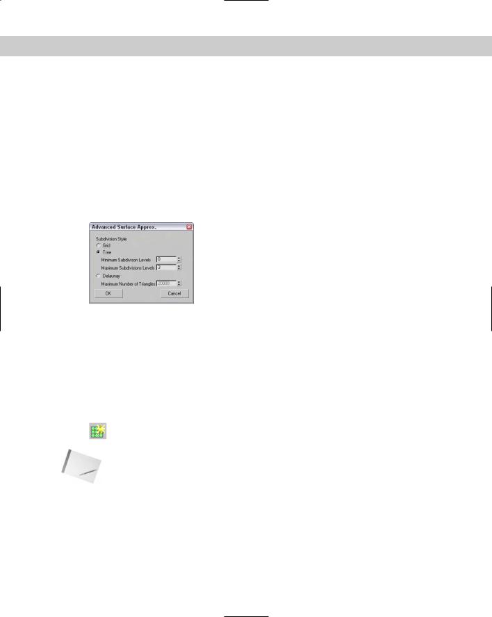
The Merge value determines the space between surfaces that should be combined to eliminate gaps when the surface is rendered. In most cases, the default value is acceptable for eliminating surface gaps. The Advanced Parameters button opens an additional dialog box of parameters, shown in Figure 16-5, where you can choose the tessellation method to use. The options include Grid (which divides the surface using a regular grid), Tree (which divides the surface using a binary tree), and Delaunay (which subdivides the surface into equilateral triangles). The selected tessellation option is used by the Spatial, Curvature, and Spatial and Curvature tessellation methods. Use the Clear Surface Level button to eliminate all Surface Approximation settings.
Figure 16-5: The Advanced Surface Approximation dialog box lets you specify subdivision levels.
The Curve Approximation rollout lets you select the number of interpolation steps to use. You can also select the Optimize or Adaptive option. These options define the number of segments that are used to represent the curve.
If you have several NURBS surfaces whose approximation settings you’d like to change at once, you can use the Surface Approximation Utility found in the Utility panel. This utility includes the same settings found in the Surface Approximation and Surface Display rollouts, but can be applied to multiple NURBS objects at once.
The NURBS Creation Toolbox
Clicking the NURBS Creation Toolbox button in the General rollout opens the toolbox shown in Figure 16-6. Clicking the button a second time closes the toolbox. This toolbox
has three sections: Points, Curves, and Surfaces.
Note |
You can also open the NURBS Creation Toolbox by using the Ctrl+T keyboard shortcut. |
Each of these sections includes buttons that create dependent subobjects. Dependent subobjects are objects that depend on other points, curves, or surfaces. When the parent object is changed, the dependent subobjects are changed also.
The Points section includes buttons for creating dependent NURBS points. Table 16-1 describes these point types and their respective buttons.
460 Part III Modeling
Figure 16-6: The NURBS Creation Toolbox lets you work with NURBS points, curves, and surfaces.
Table 16-1: Points NURBS Creation Toolbox Buttons
Toolbar Button |
Name |
Description |
|
|
|
|
Create Point |
Creates a free independent point |
|
Create Offset Point |
Creates a point that is offset from another point |
|
Create Curve Point |
Creates a point that is on a curve |
|
Create Curve-Curve Point |
Creates a point that intersects two curves |
|
Create Surf Point |
Creates a point that is on a surface |
|
Create Surface Curve Point |
Creates a point that intersects a curve |
|
|
and a surface |
|
|
|
Creating freestanding or dependent NURBS points gives you another way to build curves. When one of these buttons is selected, the cursor changes when it is positioned over a place where the point can be created. For example, clicking the Create Surf Point button causes the cursor in the viewport to change when it is over a NURBS surface.
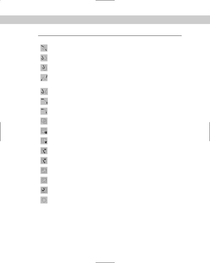
The Curves section includes many more buttons than the Points section. You can use these buttons to create dependent NURBS curves. Table 16-2 describes each of these buttons.
Table 16-2: Curves NURBS Creation Toolbox Buttons
Toolbar Button |
Name |
Description |
|
|
|
|
Create CV Curve |
Creates a CV curve |
|
Create Point Curve |
Creates a point curve |
Chapter 16 Working with NURBS 461
Toolbar Button |
Name |
Description |
|
|
|
|
Create Fit Curve |
Creates a point curve that fits the selected points |
|
Create Transform Curve |
Creates a copy of a curve that is transformed |
|
Create Blend Curve |
Blends or smoothly connects the ends of two |
|
|
NURBS curves |
|
Create Offset Curve |
Creates a copy of the original curve that is larger |
|
|
or smaller and moved to one side according to |
|
|
the distance setting |
|
Create Mirror Curve |
Creates a mirrored copy of the original curve in |
|
|
the selected axis at a user-set distance |
|
Create Chamfer Curve |
Creates a bevel where two curves meet |
|
Create Fillet Curve |
Creates a radius line to make a smooth transition |
|
|
between two curves that cross each other |
|
Create Surface-Surface |
Creates a curve along the edge created when |
|
Intersection Curve |
two NURBS surfaces intersect each other |
|
Create U Iso Curve |
Creates a dependent curve from the U isoparm |
|
|
that make up the NURBS surface |
|
Create V Iso Curve |
Creates a dependent curve from the V isoparm |
|
|
that makes up the NURBS surface |
|
Create Normal |
Projects a curve on a NURBS surface by |
|
Projected Curve |
projecting along a surface normal |
|
Create Vector Projected Curve |
Projects a curve on a NURBS surface by |
|
|
projecting along a vector |
|
Create CV Curve on Surface |
Enables the user to create a CV curve directly on |
|
|
a NURBS surface |
|
Create Point Curve on Surface |
Enables the user to create a point curve directly |
|
|
on a NURBS surface |
|
Create Surface Offset Curve |
Creates a curve that is offset from a surface curve |
|
Create Surface Edge Curve |
Creates a curve that lies on the surface edge |
|
|
|
You can create dependent curve subobjects from points, curves, or surfaces. The cursor indicates when these can be created. Some dependent curves require two objects. For example, the Create Blend Curve button can attach two curves together. Selecting the first and then selecting the second does this. Each curve is highlighted blue as it is selected. The curves must be part of the same object.
462 Part III Modeling
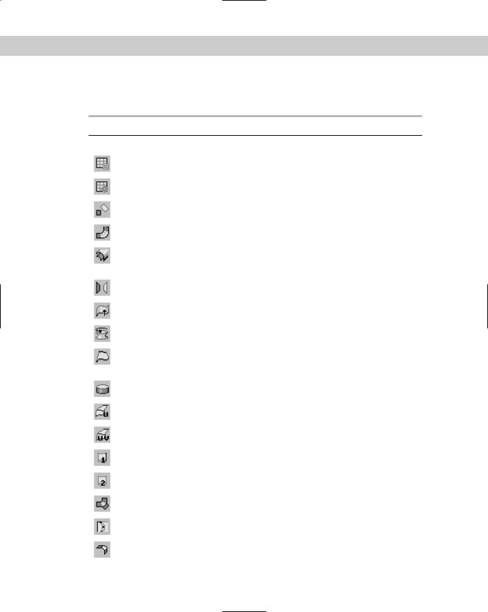
The Surfaces section includes buttons for creating dependent NURBS surfaces. Table 16-3 describes each of these buttons.
Table 16-3: Surfaces NURBS Creation Toolbox Buttons
|
Toolbar Button |
Name |
Description |
|
|
|
|
|
|
Create CV Surface |
Creates a CV surface |
|
|
Create Point Surface |
Creates a point surface |
|
|
Create Transform Surface |
Creates a copy of a surface that is transformed |
|
|
Create Blend Surface |
Connects one surface to another with a smooth |
|
|
|
surface between them |
|
|
Create Offset Surface |
Creates a copy of the original curve that is |
|
|
|
moved to one side according to the distance |
|
|
|
setting |
|
|
Create Mirror Surface |
Creates a mirrored copy of the original surface in |
|
|
|
the selected axis at a user set distance |
|
|
Create Extrude Surface |
Creates a NURBS surface at right angles to the |
|
|
|
construction plane |
|
|
Create Lathed Surface |
Creates a NURBS surface by rotating a curve |
|
|
|
about an axis |
|
|
Create Ruled Surface |
Creates a straight surface that joins the edges of |
|
|
|
two separate surfaces; one edge can be curved |
|
|
|
and the other straight |
|
|
Create Cap Surface |
Creates a surface that closes the edges of a |
|
|
|
closed surface |
|
|
Create U Loft Surface |
Creates a surface by linking multiple closed |
|
|
|
curved contours along the U axis |
|
|
Create UV Loft Surface |
Creates a surface by linking multiple closed |
|
|
|
curved contours along the U and V axes |
|
|
Create 1-Rail Sweep |
Creates a surface using an edge defined by one |
|
|
|
curve with a cross section defined by another |
|
|
Create 2-Rail Sweep |
Creates a surface using an edge defined by two |
|
|
|
curves with a cross section defined by another |
|
|
Create a Multisided |
Creates a surface by blending several curves |
|
|
Blend Surface |
and surfaces |
|
|
Create a Multicurved |
Creates a surface that is trimmed by several |
|
|
Trimmed Surface |
curves that form a loop |
|
|
Create Fillet Surface |
Creates a surface with rounded corners where |
|
|
|
the surfaces meet |
|
|
|
|