

- •Preface
- •About This Book
- •Acknowledgments
- •Contents at a Glance
- •Contents
- •Relaxing at the Beach
- •Dressing the Scene
- •Animating Motion
- •Rendering the Final Animation
- •Summary
- •The Interface Elements
- •Using the Menus
- •Using the Toolbars
- •Using the Viewports
- •Using the Command Panel
- •Using the Lower Interface Bar Controls
- •Interacting with the Interface
- •Getting Help
- •Summary
- •Understanding 3D Space
- •Using the Viewport Navigation Controls
- •Configuring the Viewports
- •Working with Viewport Backgrounds
- •Summary
- •Working with Max Scene Files
- •Setting File Preferences
- •Importing and Exporting
- •Referencing External Objects
- •Using the File Utilities
- •Accessing File Information
- •Summary
- •Customizing Modify and Utility Panel Buttons
- •Working with Custom Interfaces
- •Configuring Paths
- •Selecting System Units
- •Setting Preferences
- •Summary
- •Creating Primitive Objects
- •Exploring the Primitive Object Types
- •Summary
- •Selecting Objects
- •Setting Object Properties
- •Hiding and Freezing Objects
- •Using Layers
- •Summary
- •Cloning Objects
- •Understanding Cloning Options
- •Mirroring Objects
- •Cloning over Time
- •Spacing Cloned Objects
- •Creating Arrays of Objects
- •Summary
- •Working with Groups
- •Building Assemblies
- •Building Links between Objects
- •Displaying Links and Hierarchies
- •Working with Linked Objects
- •Summary
- •Using the Schematic View Window
- •Working with Hierarchies
- •Setting Schematic View Preferences
- •Using List Views
- •Summary
- •Working with the Transformation Tools
- •Using Pivot Points
- •Using the Align Commands
- •Using Grids
- •Using Snap Options
- •Summary
- •Exploring the Modifier Stack
- •Exploring Modifier Types
- •Summary
- •Exploring the Modeling Types
- •Working with Subobjects
- •Modeling Helpers
- •Summary
- •Drawing in 2D
- •Editing Splines
- •Using Spline Modifiers
- •Summary
- •Creating Editable Mesh and Poly Objects
- •Editing Mesh Objects
- •Editing Poly Objects
- •Using Mesh Editing Modifiers
- •Summary
- •Introducing Patch Grids
- •Editing Patches
- •Using Modifiers on Patch Objects
- •Summary
- •Creating NURBS Curves and Surfaces
- •Editing NURBS
- •Working with NURBS
- •Summary
- •Morphing Objects
- •Creating Conform Objects
- •Creating a ShapeMerge Object
- •Creating a Terrain Object
- •Using the Mesher Object
- •Working with BlobMesh Objects
- •Creating a Scatter Object
- •Creating Connect Objects
- •Modeling with Boolean Objects
- •Creating a Loft Object
- •Summary
- •Understanding the Various Particle Systems
- •Creating a Particle System
- •Using the Spray and Snow Particle Systems
- •Using the Super Spray Particle System
- •Using the Blizzard Particle System
- •Using the PArray Particle System
- •Using the PCloud Particle System
- •Using Particle System Maps
- •Controlling Particles with Particle Flow
- •Summary
- •Understanding Material Properties
- •Working with the Material Editor
- •Using the Material/Map Browser
- •Using the Material/Map Navigator
- •Summary
- •Using the Standard Material
- •Using Shading Types
- •Accessing Other Parameters
- •Using External Tools
- •Summary
- •Using Compound Materials
- •Using Raytrace Materials
- •Using the Matte/Shadow Material
- •Using the DirectX 9 Shader
- •Applying Multiple Materials
- •Material Modifiers
- •Summary
- •Understanding Maps
- •Understanding Material Map Types
- •Using the Maps Rollout
- •Using the Map Path Utility
- •Using Map Instances
- •Summary
- •Mapping Modifiers
- •Using the Unwrap UVW modifier
- •Summary
- •Working with Cameras
- •Setting Camera Parameters
- •Summary
- •Using the Camera Tracker Utility
- •Summary
- •Using Multi-Pass Cameras
- •Creating Multi-Pass Camera Effects
- •Summary
- •Understanding the Basics of Lighting
- •Getting to Know the Light Types
- •Creating and Positioning Light Objects
- •Viewing a Scene from a Light
- •Altering Light Parameters
- •Working with Photometric Lights
- •Using the Sunlight and Daylight Systems
- •Using Volume Lights
- •Summary
- •Selecting Advanced Lighting
- •Using Local Advanced Lighting Settings
- •Tutorial: Excluding objects from light tracing
- •Summary
- •Understanding Radiosity
- •Using Local and Global Advanced Lighting Settings
- •Working with Advanced Lighting Materials
- •Using Lighting Analysis
- •Summary
- •Using the Time Controls
- •Working with Keys
- •Using the Track Bar
- •Viewing and Editing Key Values
- •Using the Motion Panel
- •Using Ghosting
- •Animating Objects
- •Working with Previews
- •Wiring Parameters
- •Animation Modifiers
- •Summary
- •Understanding Controller Types
- •Assigning Controllers
- •Setting Default Controllers
- •Examining the Various Controllers
- •Summary
- •Working with Expressions in Spinners
- •Understanding the Expression Controller Interface
- •Understanding Expression Elements
- •Using Expression Controllers
- •Summary
- •Learning the Track View Interface
- •Working with Keys
- •Editing Time
- •Editing Curves
- •Filtering Tracks
- •Working with Controllers
- •Synchronizing to a Sound Track
- •Summary
- •Understanding Your Character
- •Building Bodies
- •Summary
- •Building a Bones System
- •Using the Bone Tools
- •Using the Skin Modifier
- •Summary
- •Creating Characters
- •Working with Characters
- •Using Character Animation Techniques
- •Summary
- •Forward versus Inverse Kinematics
- •Creating an Inverse Kinematics System
- •Using the Various Inverse Kinematics Methods
- •Summary
- •Creating and Binding Space Warps
- •Understanding Space Warp Types
- •Combining Particle Systems with Space Warps
- •Summary
- •Understanding Dynamics
- •Using Dynamic Objects
- •Defining Dynamic Material Properties
- •Using Dynamic Space Warps
- •Using the Dynamics Utility
- •Using the Flex Modifier
- •Summary
- •Using reactor
- •Using reactor Collections
- •Creating reactor Objects
- •Calculating and Previewing a Simulation
- •Constraining Objects
- •reactor Troubleshooting
- •Summary
- •Understanding the Max Renderers
- •Previewing with ActiveShade
- •Render Parameters
- •Rendering Preferences
- •Creating VUE Files
- •Using the Rendered Frame Window
- •Using the RAM Player
- •Reviewing the Render Types
- •Using Command-Line Rendering
- •Creating Panoramic Images
- •Getting Printer Help
- •Creating an Environment
- •Summary
- •Creating Atmospheric Effects
- •Using the Fire Effect
- •Using the Fog Effect
- •Summary
- •Using Render Elements
- •Adding Render Effects
- •Creating Lens Effects
- •Using Other Render Effects
- •Summary
- •Using Raytrace Materials
- •Using a Raytrace Map
- •Enabling mental ray
- •Summary
- •Understanding Network Rendering
- •Network Requirements
- •Setting up a Network Rendering System
- •Starting the Network Rendering System
- •Configuring the Network Manager and Servers
- •Logging Errors
- •Using the Monitor
- •Setting up Batch Rendering
- •Summary
- •Compositing with Photoshop
- •Video Editing with Premiere
- •Video Compositing with After Effects
- •Introducing Combustion
- •Using Other Compositing Solutions
- •Summary
- •Completing Post-Production with the Video Post Interface
- •Working with Sequences
- •Adding and Editing Events
- •Working with Ranges
- •Working with Lens Effects Filters
- •Summary
- •What Is MAXScript?
- •MAXScript Tools
- •Setting MAXScript Preferences
- •Types of Scripts
- •Writing Your Own MAXScripts
- •Learning the Visual MAXScript Editor Interface
- •Laying Out a Rollout
- •Summary
- •Working with Plug-Ins
- •Locating Plug-Ins
- •Summary
- •Low-Res Modeling
- •Using Channels
- •Using Vertex Colors
- •Rendering to a Texture
- •Summary
- •Max and Architecture
- •Using AEC Objects
- •Using Architectural materials
- •Summary
- •Tutorial: Creating Icy Geometry with BlobMesh
- •Tutorial: Using Caustic Photons to Create a Disco Ball
- •Summary
- •mental ray Rendering System
- •Particle Flow
- •reactor 2.0
- •Schematic View
- •BlobMesh
- •Spline and Patch Features
- •Import and Export
- •Shell Modifier
- •Vertex Paint and Channel Info
- •Architectural Primitives and Materials
- •Minor Improvements
- •Choosing an Operating System
- •Hardware Requirements
- •Installing 3ds max 6
- •Authorizing the Software
- •Setting the Display Driver
- •Updating Max
- •Moving Max to Another Computer
- •Using Keyboard Shortcuts
- •Using the Hotkey Map
- •Main Interface Shortcuts
- •Dialog Box Shortcuts
- •Miscellaneous Shortcuts
- •System Requirements
- •Using the CDs with Windows
- •What’s on the CDs
- •Troubleshooting
- •Index

452 Part III Modeling
Summary
Patches don’t have the overhead of NURBS objects and are better optimized than mesh objects. Editable Patch objects include a huge list of tools that you can use to edit and modify them. In this chapter, you learned how to create and edit patches.
More specifically, in this chapter, you
Learned to create Quad and Tri Patch grids
Discovered the features of an Editable Patch object
Worked with the Editable Patch subobjects
Worked with patch-specific modifiers such as the surface tools
Now that splines, meshes, and patches have been covered, we’ll take the escalator to the next floor, which covers NURBS in all their nurby glory.
|
|
|

Working with
NURBS
NURBS is an acronym for Non-Uniform Rational B-Splines. They are the ideal modeling tool for creating organic characters
because they are easy to work with, they give you good interactive control, they blend together seamlessly, and the surfaces remain smooth even when distorted. NURBS are superior to polygonal modeling methods when building models with smooth flowing contours such as plants, flowers, animals, and skin.
In this chapter, we explore different methods of NURBS model construction and then look at some advanced NURBS tutorials.
Creating NURBS Curves and Surfaces
If you boil down any complex NURBS object, you’ll find a collection of fundamental building pieces. These fundamental pieces consist of curves and surfaces. From these simple pieces, you can form complex models. You can create both of these fundamental pieces using the Create menu.
From the Create menu, you can create two types of NURBS curves and two types of NURBS surfaces. For both curves and surfaces, one type works with points and the other type works with control vertices (referred to as CVs). The point type includes lines that always run through the points that make up the curves or surfaces. The CV type is different. It has a lattice of points that control how the lines run. The lines do not run through the CVs, but are affected by their distance, much like how Bézier curves work.
NURBS curves
The two kinds of NURBS curves are CV curves and point curves. CV curves are the most commonly used NURBS curves. You can create both of these curves by selecting the Create NURBS menu command or by opening the Create panel, selecting the Shapes category, and selecting the NURBS Curves subcategory. Then click and drag in the viewport to set the first point and begin drawing the curve. After each click, drag the mouse to a new location, click again to continue extending the curve, and then right-click to end the curve.
16C H A P T E R
In This Chapter
Creating NURBS curves and surfaces
Converting primitive objects to NURBS
Editing point and CV curves and surfaces
Using the NURBS
Creation Toolbox
Lofting, lathing, and sweeping NURBS
454 Part III Modeling
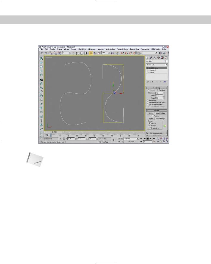
Figure 16-1 shows a NURBS point curve on the left and a NURBS CV curve on the right.
Figure 16-1: NURBS curves come in two different types: point and CV curves.
Note You can also create NURBS curves and surfaces using the NURBS Creation Toolbox, which you find out more about later in this chapter.
CV curves versus Point curves
CV curves have a CV control lattice with points (shown in the viewports as yellow) that let you control the shape of an individual curve or the entire surface. The point curve is similar to a CV curve, except that the NURBS curve passes through the points. Point curves give you more intuitive control over the shape of a curve or surface, but they are not as stable as CV curves, and point surfaces do not have as many modification options. Notice that NURBS curves are automatically smoothed, but, unlike splines, they do not have Bézier control handles to adjust their shape. You can adjust the shape of a NURBS curve by moving the control vertices or by adjusting the weights (strengths of attraction) of individual CVs.
Rendering NURBS curves
The Rendering rollout includes many of the same rendering options that apply for splines. You can make the curves renderable and give them a Thickness value. The Sides value defines the number of edges that are included in the curve cross section, and the Angle value determines how the cross section is oriented. You can also make the curves appear in the renderer and/or the viewports and have Max generate mapping coordinates. If the Display Render Mesh option is selected, then you can select to Use Viewport Settings, and the renderer will use the settings for the Viewport.
Chapter 16 Working with NURBS 455
NURBS surfaces
You can also create NURBS point surfaces and CV surfaces using the Create NURBS menu or by opening the Create panel, selecting the Geometry category, and selecting the NURBS Surfaces subcategory. Then, to create the surface, you simply click and drag to make a rectangular shape in any viewport; when you release the mouse button, the surface is built. These rectangles, also referred to as NURBS patches, are easy to form into shapes by moving, scaling, and rotating the CVs. You can build a large model by assembling a group of these NURBS patches and attaching them with various NURBS surface tools.
The Create Parameters rollout includes settings to specify the Length and Width of the surface. You can also specify the number of points or CVs the surface will have. This rollout also includes options to Generate Mapping Coordinates and Flip Normals. For CV surfaces, you can set Automatic Reparameterization to None, Chord Length, or Uniform.
CV surfaces versus Point surfaces
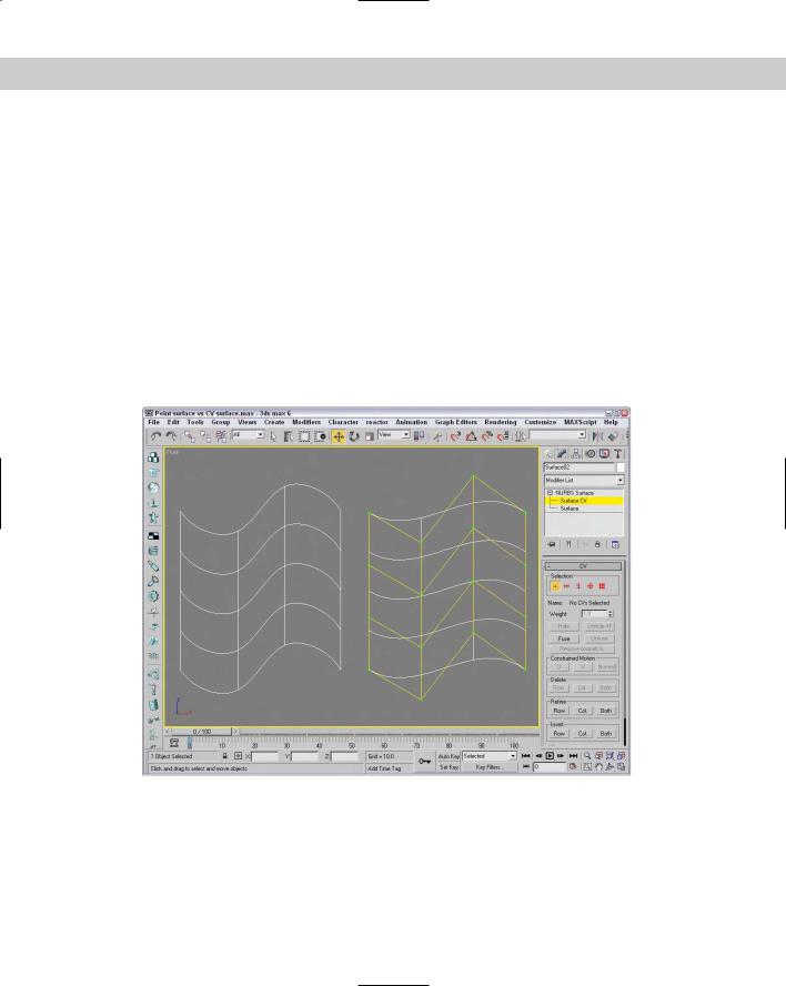
Figure 16-2 shows a NURBS point surface on the left and a NURBS CV surface on the right.
Figure 16-2: NURBS surfaces also come in two different types: point and CV surfaces.
You can create different types of NURBS surfaces from NURBS curves and patches using the various buttons found in the Create Surfaces rollout in the Modify panel. You learn more about these buttons in the sections that follow.

456 Part III Modeling
When a surface is created from two or more NURBS curves using the buttons in the Create Surfaces rollout, the surface is displayed in the form of U and V isoparms. Isoparms are lines that span the distance from one curve to the next and establish the NURBS surface. Isoparms are displayed in the viewport as green lines when a NURBS surface is selected.
Tip When building some models such as a human head, using point surfaces is often easier because you can adjust the surface interactively, and you avoid the confusion of having a complex control vertex lattice floating on top of your model, obscuring the area on which you are working.
Accessing NURBS subobjects
You can modify CV surfaces by selecting the Surface CV subobject in the Modifier Stack and moving the control vertices that surround the surface or by adjusting the weight of the individual CVs in the CV rollout. Point surfaces have no lattice, but you can shape them directly by selecting the Point subobject and moving the points on the surface.
Converting objects to NURBS
To convert a standard primitive object to a NURBS object, select the primitive object, rightclick in the viewport, and choose Convert To Convert to NURBS in the pop-up quadmenu. Another option for converting primitives is to right-click the object title in the Modifier Stack and select the Convert to NURBS option from the pop-up menu.
Figure 16-3 shows two spheres. The one on the left is a normal primitive sphere, and the one on the right has been converted to a NURBS surface.
Another method to convert a standard primitive to a NURBS object is to attach it to a NURBS object. To do this, select the NURBS object, open the Modify panel, and under the General rollout, click the Attach button and select the polygon object to attach. Any object that is attached to a NURBS object is automatically converted to a NURBS object.
Some modifiers, such as the Lathe modifier, give you the option of creating a patch, mesh, or NURBS as the output type. However, after a lathed object has been output as a polygonal mesh or a patch object, it can no longer be converted to a NURBS object.
You can also convert splines to NURBS curves, but not all types of splines convert to onepiece NURBS curves. For example, a line created using the Corner Initial type and Drag type options converts to a series of separate NURBS curves. If you want the spline to convert to a single curve, you must set the Drag type option to Smooth or Bézier. Of the many types of splines available in the Shapes category, only the Helix cannot be converted to a NURBS curve. The Rectangle, NGon, and Text shapes yield segmented NURBS curves, and closed shapes such as the Circle, Star, Ellipse, and Donut yield one-piece NURBS curves when converted.
Note If you plan to use multiple-piece curve shapes as cross sections in a 1-rail or 2-rail sweep (discussed later in the chapter) or as NURBS Extrusion curves, considering whether or not a curve is closed is important. To function properly, multiple-piece curve shapes need to be welded into a single NURBS curve after conversion.