

- •Preface
- •About This Book
- •Acknowledgments
- •Contents at a Glance
- •Contents
- •Relaxing at the Beach
- •Dressing the Scene
- •Animating Motion
- •Rendering the Final Animation
- •Summary
- •The Interface Elements
- •Using the Menus
- •Using the Toolbars
- •Using the Viewports
- •Using the Command Panel
- •Using the Lower Interface Bar Controls
- •Interacting with the Interface
- •Getting Help
- •Summary
- •Understanding 3D Space
- •Using the Viewport Navigation Controls
- •Configuring the Viewports
- •Working with Viewport Backgrounds
- •Summary
- •Working with Max Scene Files
- •Setting File Preferences
- •Importing and Exporting
- •Referencing External Objects
- •Using the File Utilities
- •Accessing File Information
- •Summary
- •Customizing Modify and Utility Panel Buttons
- •Working with Custom Interfaces
- •Configuring Paths
- •Selecting System Units
- •Setting Preferences
- •Summary
- •Creating Primitive Objects
- •Exploring the Primitive Object Types
- •Summary
- •Selecting Objects
- •Setting Object Properties
- •Hiding and Freezing Objects
- •Using Layers
- •Summary
- •Cloning Objects
- •Understanding Cloning Options
- •Mirroring Objects
- •Cloning over Time
- •Spacing Cloned Objects
- •Creating Arrays of Objects
- •Summary
- •Working with Groups
- •Building Assemblies
- •Building Links between Objects
- •Displaying Links and Hierarchies
- •Working with Linked Objects
- •Summary
- •Using the Schematic View Window
- •Working with Hierarchies
- •Setting Schematic View Preferences
- •Using List Views
- •Summary
- •Working with the Transformation Tools
- •Using Pivot Points
- •Using the Align Commands
- •Using Grids
- •Using Snap Options
- •Summary
- •Exploring the Modifier Stack
- •Exploring Modifier Types
- •Summary
- •Exploring the Modeling Types
- •Working with Subobjects
- •Modeling Helpers
- •Summary
- •Drawing in 2D
- •Editing Splines
- •Using Spline Modifiers
- •Summary
- •Creating Editable Mesh and Poly Objects
- •Editing Mesh Objects
- •Editing Poly Objects
- •Using Mesh Editing Modifiers
- •Summary
- •Introducing Patch Grids
- •Editing Patches
- •Using Modifiers on Patch Objects
- •Summary
- •Creating NURBS Curves and Surfaces
- •Editing NURBS
- •Working with NURBS
- •Summary
- •Morphing Objects
- •Creating Conform Objects
- •Creating a ShapeMerge Object
- •Creating a Terrain Object
- •Using the Mesher Object
- •Working with BlobMesh Objects
- •Creating a Scatter Object
- •Creating Connect Objects
- •Modeling with Boolean Objects
- •Creating a Loft Object
- •Summary
- •Understanding the Various Particle Systems
- •Creating a Particle System
- •Using the Spray and Snow Particle Systems
- •Using the Super Spray Particle System
- •Using the Blizzard Particle System
- •Using the PArray Particle System
- •Using the PCloud Particle System
- •Using Particle System Maps
- •Controlling Particles with Particle Flow
- •Summary
- •Understanding Material Properties
- •Working with the Material Editor
- •Using the Material/Map Browser
- •Using the Material/Map Navigator
- •Summary
- •Using the Standard Material
- •Using Shading Types
- •Accessing Other Parameters
- •Using External Tools
- •Summary
- •Using Compound Materials
- •Using Raytrace Materials
- •Using the Matte/Shadow Material
- •Using the DirectX 9 Shader
- •Applying Multiple Materials
- •Material Modifiers
- •Summary
- •Understanding Maps
- •Understanding Material Map Types
- •Using the Maps Rollout
- •Using the Map Path Utility
- •Using Map Instances
- •Summary
- •Mapping Modifiers
- •Using the Unwrap UVW modifier
- •Summary
- •Working with Cameras
- •Setting Camera Parameters
- •Summary
- •Using the Camera Tracker Utility
- •Summary
- •Using Multi-Pass Cameras
- •Creating Multi-Pass Camera Effects
- •Summary
- •Understanding the Basics of Lighting
- •Getting to Know the Light Types
- •Creating and Positioning Light Objects
- •Viewing a Scene from a Light
- •Altering Light Parameters
- •Working with Photometric Lights
- •Using the Sunlight and Daylight Systems
- •Using Volume Lights
- •Summary
- •Selecting Advanced Lighting
- •Using Local Advanced Lighting Settings
- •Tutorial: Excluding objects from light tracing
- •Summary
- •Understanding Radiosity
- •Using Local and Global Advanced Lighting Settings
- •Working with Advanced Lighting Materials
- •Using Lighting Analysis
- •Summary
- •Using the Time Controls
- •Working with Keys
- •Using the Track Bar
- •Viewing and Editing Key Values
- •Using the Motion Panel
- •Using Ghosting
- •Animating Objects
- •Working with Previews
- •Wiring Parameters
- •Animation Modifiers
- •Summary
- •Understanding Controller Types
- •Assigning Controllers
- •Setting Default Controllers
- •Examining the Various Controllers
- •Summary
- •Working with Expressions in Spinners
- •Understanding the Expression Controller Interface
- •Understanding Expression Elements
- •Using Expression Controllers
- •Summary
- •Learning the Track View Interface
- •Working with Keys
- •Editing Time
- •Editing Curves
- •Filtering Tracks
- •Working with Controllers
- •Synchronizing to a Sound Track
- •Summary
- •Understanding Your Character
- •Building Bodies
- •Summary
- •Building a Bones System
- •Using the Bone Tools
- •Using the Skin Modifier
- •Summary
- •Creating Characters
- •Working with Characters
- •Using Character Animation Techniques
- •Summary
- •Forward versus Inverse Kinematics
- •Creating an Inverse Kinematics System
- •Using the Various Inverse Kinematics Methods
- •Summary
- •Creating and Binding Space Warps
- •Understanding Space Warp Types
- •Combining Particle Systems with Space Warps
- •Summary
- •Understanding Dynamics
- •Using Dynamic Objects
- •Defining Dynamic Material Properties
- •Using Dynamic Space Warps
- •Using the Dynamics Utility
- •Using the Flex Modifier
- •Summary
- •Using reactor
- •Using reactor Collections
- •Creating reactor Objects
- •Calculating and Previewing a Simulation
- •Constraining Objects
- •reactor Troubleshooting
- •Summary
- •Understanding the Max Renderers
- •Previewing with ActiveShade
- •Render Parameters
- •Rendering Preferences
- •Creating VUE Files
- •Using the Rendered Frame Window
- •Using the RAM Player
- •Reviewing the Render Types
- •Using Command-Line Rendering
- •Creating Panoramic Images
- •Getting Printer Help
- •Creating an Environment
- •Summary
- •Creating Atmospheric Effects
- •Using the Fire Effect
- •Using the Fog Effect
- •Summary
- •Using Render Elements
- •Adding Render Effects
- •Creating Lens Effects
- •Using Other Render Effects
- •Summary
- •Using Raytrace Materials
- •Using a Raytrace Map
- •Enabling mental ray
- •Summary
- •Understanding Network Rendering
- •Network Requirements
- •Setting up a Network Rendering System
- •Starting the Network Rendering System
- •Configuring the Network Manager and Servers
- •Logging Errors
- •Using the Monitor
- •Setting up Batch Rendering
- •Summary
- •Compositing with Photoshop
- •Video Editing with Premiere
- •Video Compositing with After Effects
- •Introducing Combustion
- •Using Other Compositing Solutions
- •Summary
- •Completing Post-Production with the Video Post Interface
- •Working with Sequences
- •Adding and Editing Events
- •Working with Ranges
- •Working with Lens Effects Filters
- •Summary
- •What Is MAXScript?
- •MAXScript Tools
- •Setting MAXScript Preferences
- •Types of Scripts
- •Writing Your Own MAXScripts
- •Learning the Visual MAXScript Editor Interface
- •Laying Out a Rollout
- •Summary
- •Working with Plug-Ins
- •Locating Plug-Ins
- •Summary
- •Low-Res Modeling
- •Using Channels
- •Using Vertex Colors
- •Rendering to a Texture
- •Summary
- •Max and Architecture
- •Using AEC Objects
- •Using Architectural materials
- •Summary
- •Tutorial: Creating Icy Geometry with BlobMesh
- •Tutorial: Using Caustic Photons to Create a Disco Ball
- •Summary
- •mental ray Rendering System
- •Particle Flow
- •reactor 2.0
- •Schematic View
- •BlobMesh
- •Spline and Patch Features
- •Import and Export
- •Shell Modifier
- •Vertex Paint and Channel Info
- •Architectural Primitives and Materials
- •Minor Improvements
- •Choosing an Operating System
- •Hardware Requirements
- •Installing 3ds max 6
- •Authorizing the Software
- •Setting the Display Driver
- •Updating Max
- •Moving Max to Another Computer
- •Using Keyboard Shortcuts
- •Using the Hotkey Map
- •Main Interface Shortcuts
- •Dialog Box Shortcuts
- •Miscellaneous Shortcuts
- •System Requirements
- •Using the CDs with Windows
- •What’s on the CDs
- •Troubleshooting
- •Index
Chapter 40 Animating with reactor 969
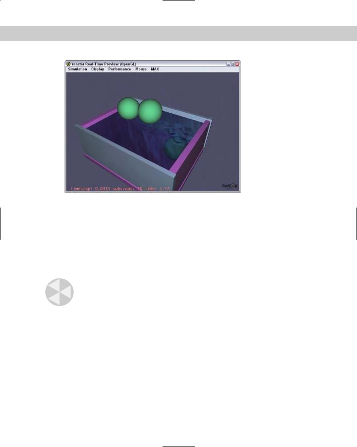
Figure 40-9: Depending on the mass property, objects sink or float.
Calculating and Previewing a Simulation
Although you’ve already had some experience with the Preview window in the examples, more controls are available than just playing the animation. To preview the simulation, select reactor Preview Animation or click the Preview Animation button on the reactor toolbar. This opens the Havok window like the one shown in Figure 40-10. This window lets you play with your simulation. The Simulation Play/Pause menu (keyboard shortcut, P) executes the simulation. Dragging with the left mouse button rotates the scene, and you can zoom in and out with the scroll wheel.
Caution |
The Preview window runs only if the OpenGL or the Direct3D display drivers are used. The |
|
window uses OpenGL by default, or you can set it to use DirectX with the DirectX option in |
|
the Display rollout. The display driver that is being used is displayed in the title bar of the |
|
Preview window. |
Using the Preview window
The fun part of the preview window is that you can interact with the objects. Right-clicking (when the simulation is playing) and dragging on the object moves it. If you find a position that you want to capture for Max, you can use the MAX Update Max menu command to set the starting positions of the objects in Max.
970 Part IX Dynamics
Figure 40-10: The Preview window is a fun place to play with a simulation.
If you want to reset the animation to its starting positions, you can use the Simulation Reset menu command. The Display menu includes several options that you can turn on to change the display. Objects can be seen as Faces or Wireframes. If you have a particularly complex scene to preview, then wireframes may be easy to work with. You can also display the Simulation Edges (which shows the collision boundaries of the objects), Grids, the Origin, and a Flashlight to add light to the scene. The Display menu also includes a Camera Settings option that you can use to set the near and far Clipping Planes and the Preview window’s Field of View.
The Performance menu includes options for setting the frames per second and the number of substeps used to compute the simulation. For most animations, the default of 10 substeps is sufficient, but if you want Max to spend more time computing an accurate solution, you can try a higher substep value.
Caution |
Don’t use a high substep value with water. |
Creating animation keys
To compute the animation keys for the simulation, select the reactor Create Animation menu command or press the Create Animation button in the reactor toolbar. The progress is displayed at the bottom of the Max interface. You can cancel the simulation at any time with the Esc key.

Chapter 40 Animating with reactor 971
Analyzing the scene
After the Preview window is opened, a warning dialog box appears if the scene has any errors or warnings that could cause trouble with the simulation. It also warns of unrealistic data, such as property settings that are too high or too low.
Tip The one warning that isn’t included in the warning dialog box is if objects have no Mass value. If objects in your simulation are just sitting there, then make sure that they have a Mass value.
If you want to check your scene without opening the Preview window, you can use the reactor Utilities Analyze World menu command. This command checks your scene for any trouble and presents problems in a dialog box. If no problems are found, then a separate dialog box tells you that no problems were found.
Tutorial: Dropping a plate of donuts
All the great books have an element of tragedy, so consider a policeman carrying a dozen donuts on a plate when he stumbles and drops the plate. Donuts everywhere, how tragic! This animation sequence would be difficult or at least time-consuming, but not with reactor.
To use reactor to animate a falling plate of donuts, follow these steps:
1.Open the Falling plate of donuts.max file from the Chap 40 directory on the CD-ROM. This file includes a simple plate of donuts created from primitives.
2.Select the reactor Create Objects Rigid Body Collection menu command, and click in the Front viewport. In the RB Collection Properties rollout, click the Pick button and select the plate object. Click the Pick button again, and select the Box object that represents the floor.
3.Select the Torus object and choose reactor Apply Modifier Soft Body Modifier (or click the Soft Body Modifier button in the reactor toolbar).
4.Then select reactor Create Objects Soft Body Collection, and click again in the Front viewport. In the SB Collection Properties rollout, click the Add button and select all the Torus objects again.
5.Select reactor Open Property Editor, and select the Box object; in the Properties rollout, enable the Unyielding option. Select the plate object, and make its Mass value 5.0. Then select all the donuts, and make their Mass value 0.25. Enable the Mesh Convex Hull option.
6.The last step is to execute the simulation. This is done with the reactor Create Animation menu command. It takes some time to compute a solution for this example. When it completes, press the Play Animation button (or press the / key) to see the results.
Figure 40-11 shows the upturned plate of donuts.
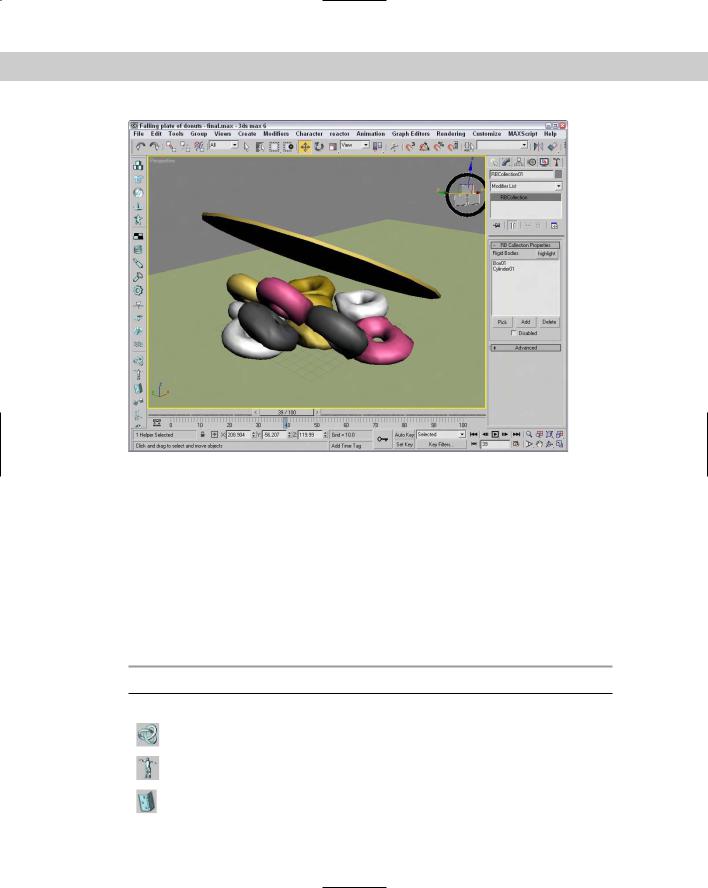
972 Part IX Dynamics
Figure 40-11: Animating these falling donuts, simulated as soft body objects, was easy with reactor.
Constraining Objects
Constraints are ways to limit the amount of motion that an object can do. Using constraints can help control objects in the scene as they interact with other objects. Perhaps the simplest constraint is to enable the Unyielding option in the Property Editor. This option makes a rigid body that won’t move and is a good option for the ground plane.
Other constraints are found in the reactor Create Objects menu and consist of Constraint Solver, Rag Doll Constraint, Hinge Constraint, Point-Point Constraint, Prismatic Constraint, Car-Wheel Constraint, and Point-Path Constraint, as listed in Table 40-4.
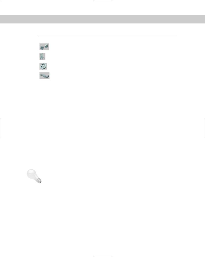
Table 40-4: reactor Constraints
Toolbar Button Name |
Description |
|
|
Constraint Solver |
Contains all active constraints used in the scene |
Rag Doll Constraint |
Causes a model to act as a human figure |
Hinge Constraint |
Allows angular rotation like a hinge |
Chapter 40 Animating with reactor 973
Toolbar Button Name |
Description |
|
|
Point-Point Constraint |
Links two points together; good for rope ends |
Prismatic Constraint |
Used to constrain the motion of two rigid bodies to a single |
|
axis with no rotation |
Car-Wheel Constraint |
Causes a car to move linearly as a wheel object is rotated |
Point-Path Constraint |
Limits a point to move only along a path |
|
|
After a constraint object is added to the scene, you can select the objects that will be included as child and parent objects using the buttons in the Properties rollout. The Properties rollout also includes buttons to align the constraint to the Child Body, Parent Body, Child Space or Parent Space. For each constraint, you can set the Strength and Tau of the connection. This determines how strong the link is and how easily broken. In addition to the Strength and Tau values, you can set Limits and allow the hinge to be Breakable under a defined Linear or Angular force value.
When a constraint’s Child is first selected, the Constraint’s icon is positioned at the pivot point of the child object. If you look in the Modifier Stack for the Constraint object, you’ll find subobject modes for Child Space and Parent Space. If you select these subobject modes, you can change the position of the constraint’s child and parent objects.
|
Using a Constraint Solver |
|
In order to use most constraints, you need to add a Constraint Solver to the scene. Then you |
|
can use the Modify panel to add Constraints to the list to be solved. The Constraint Solver |
|
needs to know about any Rigid Body Collections that are attached to any Constraints in the |
|
scene. To identify all the Constraints that are part of the Constraint Solver, click the Highlight |
|
button. |
Tip |
If the simulation includes any constraints that the Constraint Solver doesn’t know about, the |
|
Constraint Solver icon appears red in the viewports. |
Rag Doll constraint
The Rag Doll constraint defines all the joint limits common in a human figure. It can be used to animate a lifeless body colliding with various rigid body objects. Using the Rag Doll constraint, you can manually define how the body joints can twist, rotate, and move.
These joints are fairly common for human bodies. Discreet has created a script to create a human body proxy that creates a rag doll with the correct constraints already defined. The script is named rctRagdollScript.ms. It can be found in the scripts directory where 3dsmax is installed.

974 Part IX Dynamics
You can execute this script by opening the Utilities panel, clicking the MAXScript button, and clicking the Run Script button. This opens a file dialog box. Locate the script, click Open, and the script runs. Running this script opens the Rag Doll dialog box, shown in Figure 40-12. Using this dialog box, you can provide a Name for the rag doll and set its Height and the number of Vertebra. The Create Humanoid button makes the rag doll appear in the viewports.
Once positioned, you can press the Constrain Humanoid button in the Constrain Humanoid rollout. This adds all the necessary constrains to the rag doll.
Figure 40-12: Fully constrained humanoid figures can be created using the rctRagdollScript.ms script.
The Point-to-Point constraint lets you attach two objects together by a common point. The attach point is the pivot point of the child and parent objects. It can be used to animate a lifeless body colliding with various rigid body objects. Using the Rag Doll constraint, you can manually define how the body joints can twist, rotate, and move.
Tutorial: Swinging into a wall
Playing with the rag doll object is just plain fun. Remember that in the Preview window you can use the right-click button to throw the doll around. For this example, we use a couple of Point-to-Point Constraints along with a Rag Doll constraint to create a simple scene where the rag doll swings from a rope into a brick wall.
To animate a rag doll swinging on a rope, follow these steps:
1.Open the Swinging into a wall.max file from the Chap 40 directory on the CD-ROM.
This file includes a simple scene consisting of several Boxes, a Cylinder for the rope, and a brick wall.
2.Open the Utilities panel and click on the MAXScript button. Click the Run Script button in the MAXScript rollout. In the file dialog box, locate the Scripts directory where Max is installed. Select the rctRagdollScript.ms file and click the Open button.
3.In the Rag Doll panel that appears, open the Create Humanoid rollout and click the Create Humanoid button. Then move the Rag Doll panel to the side, but don’t close it. Select the rag doll that appears at the origin and move it so one of its hands is positioned close to the end of the Cylinder object.
Chapter 40 Animating with reactor 975
4.In the Rag Doll panel, open the Constrain Humanoid rollout and click the Constrain Humanoid button. This automatically adds all the needed constraints for the rag doll. Then close the Rag Doll panel.
5.Select the Cylinder object and choose reactor Create Object Point-Point Constraint and click in the Left viewport close to the rag doll. In the Properties rollout, click the Child button and select the hand object that is close to the Cylinder. Then enable the Parent option, click the Parent object, and select the Cylinder. Open the Modify panel, select the Parent Space subobject mode, and move the gizmo in the Front viewport to be on the Cylinder. Do the same for the Child Space subobject. This defines where the two objects will be attached.
6.Repeat Step 5 to create a Point-to-Point Constraint where the Cylinder touches the roof object with the Cylinder as the Child object and the roof as the Parent object.
7.Press the H key to open the Select Objects dialog box and select the RagdollRBCollection object. Then click the Add button in the RB Collection Properties rollout. Click the All button in the Select Rigid Bodies dialog box and click Select. Repeat this step for the RagdollCSolver icon to add the two new Point-to-Point Constraints.
8.Select all three Box objects in the scene and choose reactor Open Property Editor. In the Physical Properties rollout, enable the Unyielding option. Then select the Cylinder object and set its Mass value to 0.5.
9.Select reactor Preview Animation to see the resulting preview. Then select reactor Create Animation to create the animation keys.
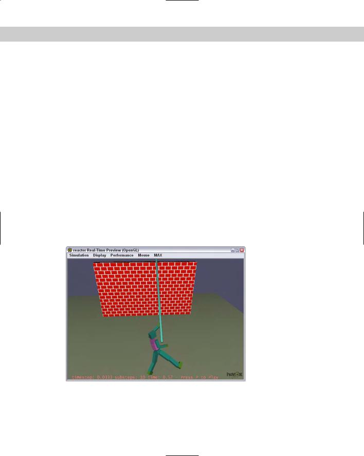
Figure 40-13 shows the swinging rag doll.
Figure 40-13: Using constraints gives you control over the animation motion.