

- •Preface
- •About This Book
- •Acknowledgments
- •Contents at a Glance
- •Contents
- •Relaxing at the Beach
- •Dressing the Scene
- •Animating Motion
- •Rendering the Final Animation
- •Summary
- •The Interface Elements
- •Using the Menus
- •Using the Toolbars
- •Using the Viewports
- •Using the Command Panel
- •Using the Lower Interface Bar Controls
- •Interacting with the Interface
- •Getting Help
- •Summary
- •Understanding 3D Space
- •Using the Viewport Navigation Controls
- •Configuring the Viewports
- •Working with Viewport Backgrounds
- •Summary
- •Working with Max Scene Files
- •Setting File Preferences
- •Importing and Exporting
- •Referencing External Objects
- •Using the File Utilities
- •Accessing File Information
- •Summary
- •Customizing Modify and Utility Panel Buttons
- •Working with Custom Interfaces
- •Configuring Paths
- •Selecting System Units
- •Setting Preferences
- •Summary
- •Creating Primitive Objects
- •Exploring the Primitive Object Types
- •Summary
- •Selecting Objects
- •Setting Object Properties
- •Hiding and Freezing Objects
- •Using Layers
- •Summary
- •Cloning Objects
- •Understanding Cloning Options
- •Mirroring Objects
- •Cloning over Time
- •Spacing Cloned Objects
- •Creating Arrays of Objects
- •Summary
- •Working with Groups
- •Building Assemblies
- •Building Links between Objects
- •Displaying Links and Hierarchies
- •Working with Linked Objects
- •Summary
- •Using the Schematic View Window
- •Working with Hierarchies
- •Setting Schematic View Preferences
- •Using List Views
- •Summary
- •Working with the Transformation Tools
- •Using Pivot Points
- •Using the Align Commands
- •Using Grids
- •Using Snap Options
- •Summary
- •Exploring the Modifier Stack
- •Exploring Modifier Types
- •Summary
- •Exploring the Modeling Types
- •Working with Subobjects
- •Modeling Helpers
- •Summary
- •Drawing in 2D
- •Editing Splines
- •Using Spline Modifiers
- •Summary
- •Creating Editable Mesh and Poly Objects
- •Editing Mesh Objects
- •Editing Poly Objects
- •Using Mesh Editing Modifiers
- •Summary
- •Introducing Patch Grids
- •Editing Patches
- •Using Modifiers on Patch Objects
- •Summary
- •Creating NURBS Curves and Surfaces
- •Editing NURBS
- •Working with NURBS
- •Summary
- •Morphing Objects
- •Creating Conform Objects
- •Creating a ShapeMerge Object
- •Creating a Terrain Object
- •Using the Mesher Object
- •Working with BlobMesh Objects
- •Creating a Scatter Object
- •Creating Connect Objects
- •Modeling with Boolean Objects
- •Creating a Loft Object
- •Summary
- •Understanding the Various Particle Systems
- •Creating a Particle System
- •Using the Spray and Snow Particle Systems
- •Using the Super Spray Particle System
- •Using the Blizzard Particle System
- •Using the PArray Particle System
- •Using the PCloud Particle System
- •Using Particle System Maps
- •Controlling Particles with Particle Flow
- •Summary
- •Understanding Material Properties
- •Working with the Material Editor
- •Using the Material/Map Browser
- •Using the Material/Map Navigator
- •Summary
- •Using the Standard Material
- •Using Shading Types
- •Accessing Other Parameters
- •Using External Tools
- •Summary
- •Using Compound Materials
- •Using Raytrace Materials
- •Using the Matte/Shadow Material
- •Using the DirectX 9 Shader
- •Applying Multiple Materials
- •Material Modifiers
- •Summary
- •Understanding Maps
- •Understanding Material Map Types
- •Using the Maps Rollout
- •Using the Map Path Utility
- •Using Map Instances
- •Summary
- •Mapping Modifiers
- •Using the Unwrap UVW modifier
- •Summary
- •Working with Cameras
- •Setting Camera Parameters
- •Summary
- •Using the Camera Tracker Utility
- •Summary
- •Using Multi-Pass Cameras
- •Creating Multi-Pass Camera Effects
- •Summary
- •Understanding the Basics of Lighting
- •Getting to Know the Light Types
- •Creating and Positioning Light Objects
- •Viewing a Scene from a Light
- •Altering Light Parameters
- •Working with Photometric Lights
- •Using the Sunlight and Daylight Systems
- •Using Volume Lights
- •Summary
- •Selecting Advanced Lighting
- •Using Local Advanced Lighting Settings
- •Tutorial: Excluding objects from light tracing
- •Summary
- •Understanding Radiosity
- •Using Local and Global Advanced Lighting Settings
- •Working with Advanced Lighting Materials
- •Using Lighting Analysis
- •Summary
- •Using the Time Controls
- •Working with Keys
- •Using the Track Bar
- •Viewing and Editing Key Values
- •Using the Motion Panel
- •Using Ghosting
- •Animating Objects
- •Working with Previews
- •Wiring Parameters
- •Animation Modifiers
- •Summary
- •Understanding Controller Types
- •Assigning Controllers
- •Setting Default Controllers
- •Examining the Various Controllers
- •Summary
- •Working with Expressions in Spinners
- •Understanding the Expression Controller Interface
- •Understanding Expression Elements
- •Using Expression Controllers
- •Summary
- •Learning the Track View Interface
- •Working with Keys
- •Editing Time
- •Editing Curves
- •Filtering Tracks
- •Working with Controllers
- •Synchronizing to a Sound Track
- •Summary
- •Understanding Your Character
- •Building Bodies
- •Summary
- •Building a Bones System
- •Using the Bone Tools
- •Using the Skin Modifier
- •Summary
- •Creating Characters
- •Working with Characters
- •Using Character Animation Techniques
- •Summary
- •Forward versus Inverse Kinematics
- •Creating an Inverse Kinematics System
- •Using the Various Inverse Kinematics Methods
- •Summary
- •Creating and Binding Space Warps
- •Understanding Space Warp Types
- •Combining Particle Systems with Space Warps
- •Summary
- •Understanding Dynamics
- •Using Dynamic Objects
- •Defining Dynamic Material Properties
- •Using Dynamic Space Warps
- •Using the Dynamics Utility
- •Using the Flex Modifier
- •Summary
- •Using reactor
- •Using reactor Collections
- •Creating reactor Objects
- •Calculating and Previewing a Simulation
- •Constraining Objects
- •reactor Troubleshooting
- •Summary
- •Understanding the Max Renderers
- •Previewing with ActiveShade
- •Render Parameters
- •Rendering Preferences
- •Creating VUE Files
- •Using the Rendered Frame Window
- •Using the RAM Player
- •Reviewing the Render Types
- •Using Command-Line Rendering
- •Creating Panoramic Images
- •Getting Printer Help
- •Creating an Environment
- •Summary
- •Creating Atmospheric Effects
- •Using the Fire Effect
- •Using the Fog Effect
- •Summary
- •Using Render Elements
- •Adding Render Effects
- •Creating Lens Effects
- •Using Other Render Effects
- •Summary
- •Using Raytrace Materials
- •Using a Raytrace Map
- •Enabling mental ray
- •Summary
- •Understanding Network Rendering
- •Network Requirements
- •Setting up a Network Rendering System
- •Starting the Network Rendering System
- •Configuring the Network Manager and Servers
- •Logging Errors
- •Using the Monitor
- •Setting up Batch Rendering
- •Summary
- •Compositing with Photoshop
- •Video Editing with Premiere
- •Video Compositing with After Effects
- •Introducing Combustion
- •Using Other Compositing Solutions
- •Summary
- •Completing Post-Production with the Video Post Interface
- •Working with Sequences
- •Adding and Editing Events
- •Working with Ranges
- •Working with Lens Effects Filters
- •Summary
- •What Is MAXScript?
- •MAXScript Tools
- •Setting MAXScript Preferences
- •Types of Scripts
- •Writing Your Own MAXScripts
- •Learning the Visual MAXScript Editor Interface
- •Laying Out a Rollout
- •Summary
- •Working with Plug-Ins
- •Locating Plug-Ins
- •Summary
- •Low-Res Modeling
- •Using Channels
- •Using Vertex Colors
- •Rendering to a Texture
- •Summary
- •Max and Architecture
- •Using AEC Objects
- •Using Architectural materials
- •Summary
- •Tutorial: Creating Icy Geometry with BlobMesh
- •Tutorial: Using Caustic Photons to Create a Disco Ball
- •Summary
- •mental ray Rendering System
- •Particle Flow
- •reactor 2.0
- •Schematic View
- •BlobMesh
- •Spline and Patch Features
- •Import and Export
- •Shell Modifier
- •Vertex Paint and Channel Info
- •Architectural Primitives and Materials
- •Minor Improvements
- •Choosing an Operating System
- •Hardware Requirements
- •Installing 3ds max 6
- •Authorizing the Software
- •Setting the Display Driver
- •Updating Max
- •Moving Max to Another Computer
- •Using Keyboard Shortcuts
- •Using the Hotkey Map
- •Main Interface Shortcuts
- •Dialog Box Shortcuts
- •Miscellaneous Shortcuts
- •System Requirements
- •Using the CDs with Windows
- •What’s on the CDs
- •Troubleshooting
- •Index
Chapter 13 Drawing and Editing 2D Splines and Shapes |
381 |
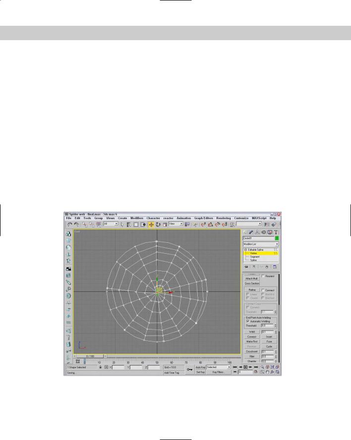
5.Select the circle shape, and click the Trim button. Then click on each line segment on the portion that extends beyond the circle. This trims the radial lines to the edge of the circle. Click the Trim button again when you are finished to exit Trim mode.
6.Change to Vertex subobject mode by clicking Vertex in the Modifier Stack (or by pressing 1). Then select all the vertices in the center of the circle, and click the Fuse and Weld buttons.
Figure 13-33 shows the finished spider web. (I have a new respect for spiders.)
Using Spline Modifiers
In the Modifiers menu is a whole submenu of modifiers that apply strictly to splines. You can find these modifiers in the Modifiers Patch/Spline Editing menu.
Spline-specific modifiers
Of the modifiers that work only on splines, several of these duplicate functionality that is available for Editable Splines, such as the Fillet/Chamfer modifier. Applying these features as modifiers gives you better control over the results because you can remove them using the Modifier Stack at any time.
Figure 13-33: A spider web made from Editable Splines
382 Part III Modeling
Edit Spline modifier
The Edit Spline modifier (mentioned at the start of the chapter) makes spline objects so they can be edited. It has all the same features as the Editable Spline object. The Edit Spline modifier isn’t really a modifier, but an Object type. It shows up in the Modifier Stack above the base object. The key benefit of the Edit Spline modifier is that it enables you to edit spline subobjects while maintaining the parametric nature of the primitive object.
Spline Select modifier
This modifier enables you to select spline subobjects, including Vertex, Segment, and Spline. You can copy and paste named selection sets. The selection can then be passed up the Stack to the next modifier. The Spline Select modifier provides a way to apply a modifier to a subobject selection.
The Spline Select modifier lets you select objects from any of the subobject modes available in the Editable Spline object. It also includes buttons for selecting subobjects based on the other subobject modes. For example, if you select Vertex subobject mode, then two buttons available in the Select Vertex rollout are Get Segment Selection and Get Spline Selection. Clicking either of these buttons gets all the vertices that are part of the other subobject mode.
You can also Copy and Paste selection sets using the Copy and Paste buttons.
Delete Spline modifier
You can use the Delete Spline modifier to delete spline subobjects. Another good use of this modifier is to hide splines that are used for other purposes. For example, when creating an animation path, you can apply this modifier to the path to hide it, but by removing this modifier, you can get back to the base spline at any time.
Normalize Spline modifier
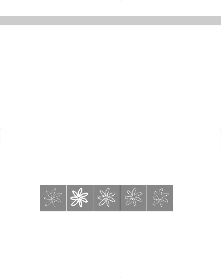
The Normalize Spline modifier adds new points to the spline. These points are spaced regularly based on the Segment Length value. This provides a quick way to optimize a spline. Figure 13-34 shows a simple flower shape with the Spline Select modifier applied so you can see the vertices. The Normalize Spline modifier was then applied with Segment Length values of 1, 5, 10, and 15. Notice that the shape is changing with fewer vertices.
Figure 13-34: The Normalize Spline modifier relaxes the shape by removing vertices.
Fillet/Chamfer modifier
You can use the Fillet/Chamfer modifier to Fillet or Chamfer the corners of shapes. Fillets create a smooth corner, and a Chamfer adds another segment where two edges meet. Parameters include the Fillet Radius and the Chamfer Distance. Both include an Apply button. The results of this modifier are the same as if you were to use the Fillet or Chamfer features of an Editable Spline.
Chapter 13 Drawing and Editing 2D Splines and Shapes |
383 |
Trim/Extend modifier
The Trim/Extend modifier lets you trim the extending end of a spline or extend a spline until it meets another spline at a vertex. The Pick Locations button turns on Pick mode, where the cursor changes when it is over a valid point. Operations include Auto, Trim Only, and Extend Only with an option to compute Infinite Boundaries. You can also set the Intersection Projection to View, Construction Plane, or None.
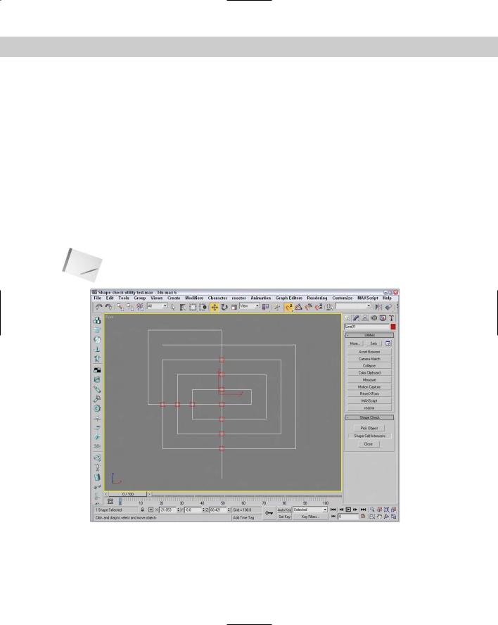
Using the Shape Check utility
The Shape Check utility is helpful in verifying that a shape doesn’t intersect itself. Shapes that have this problem cannot be extruded, lofted, or lathed without problems. To use this utility, open the Utilities panel (the icon for the Utilities panel looks like a hammer) and click the More button. Select Shape Check from the Utilities dialog box list, and click OK.
The Shape Check rollout includes only two buttons: Pick Object and Close. Click the Pick Object button, and click the shape you want to check. Any intersection points are displayed as red squares, as shown in Figure 13-35, and the response field displays “Shape Self-Intersects.” If the shape doesn’t have any intersections, then the response field reports, “Shape OK.”
Note |
You can use the Shape Check utility on normal splines and on NURBS splines. |
Figure 13-35: The Shape Check utility can identify spline intersections.
384 Part III Modeling
Moving Splines to 3D
Although splines can be rendered, the real benefit of splines in Max is to use them to create 3D objects and for animation paths. You can use splines in several ways as you model 3D objects including Loft objects and modifiers. One way to use splines to make 3D objects is with modifiers.
Cross-
Reference
Using splines to create an animation path is covered in Chapter 30, “Animation Basics,” and Loft objects are covered in Chapter 17, “Building Compound Objects.” General information on working with modifiers is covered in Chapter 11, “Introducing Modifiers for Basic Object Deformation.”
Extruding splines
Because splines are drawn in a 2D plane, they already include two of the three dimensions. By adding a Height value to the shape, we can create a simple 3D object. The process of adding Height to a shape is called extruding.
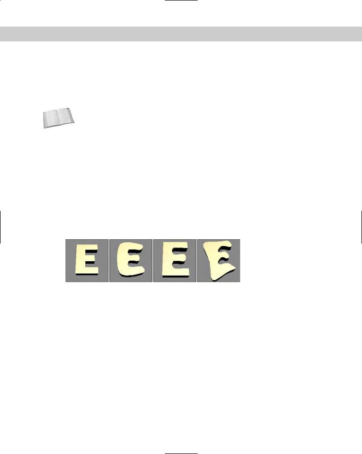
To extrude a shape, you need to apply the Extrude modifier. To do so, select a spline object and choose Modifiers Mesh Editing Extrude, or select the Extrude modifier from the Modifier Stack drop-down list. In the Parameters rollout, you can specify an Amount, which is the height value of the extrusion; the number of Segments; and the Capping options (caps fill in the surface at each end of the Extruded shape). You can also specify the final Output to be a Patch, Mesh, or NURBS object. Figure 13-36 shows our capital Es that modeled the various vertex types extruded to a depth of 10.0.
Figure 13-36: Extruding simple shapes adds depth to the spline.
Tutorial: Routing a custom shelf
In Woodshop 101, you use a router to add a designer edge to doorframes, window frames, and shelving of all sorts. In Woodshop 3D, the Boolean tools work nicely as we customize a bookshelf.
To create a custom bookshelf using spline Boolean operations, follow these steps:
1.Open the Bookshelf.max file from the Chap 13 directory on the CD-ROM. This file includes a triangle shape drawn with the Line primitive that is overlapped by three circles. All these shapes have been converted to Editable Splines.
2.With the triangle shape selected, open the Modify panel and select the Spline subobject mode (or press the 3 key).
3.Select the Subtraction Boolean operation (the middle icon) in the Geometry rollout, and click the Boolean button. Then select each of the circles.
Chapter 13 Drawing and Editing 2D Splines and Shapes |
385 |
4.Click the Subtraction button next to the Boolean button (it’s the middle one). Then select the triangle shape, and click the Boolean button. Right-click in the viewport to exit Boolean mode, and click Spline in the Modifier Stack again to exit subobject mode.
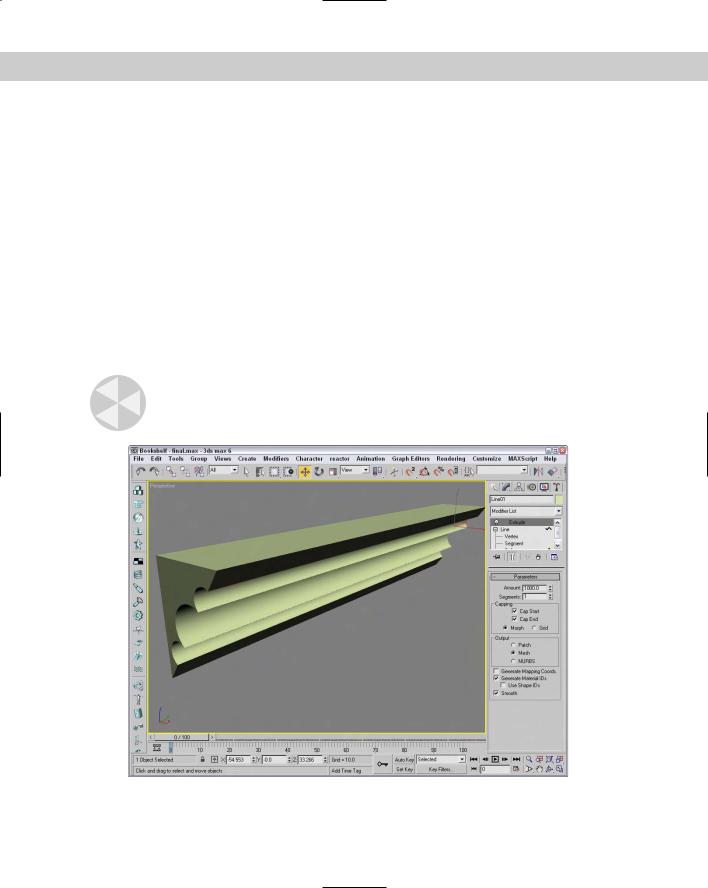
5.Back in the Modify panel, select the Extrude modifier from the Modifier drop-down list and enter an Amount of 1000. Select Zoom Extents All to resize your viewports and view your bookshelf.
Figure 13-37 shows the finished bookshelf in the Perspective viewport ready to hang on the wall.
Lathing splines
Another useful modifier for 2D splines is the Lathe. This modifier rotates the spline about an axis to create an object with a circular cross section (such as a baseball bat). In the Parameters rollout, you can specify the Degrees to rotate (a value of 360 makes a full rotation) and Cappings, which add ends to the resulting mesh. Additional options include Weld Core, which causes all vertices at the center of the lathe to be welded together, and Flip Normals, which realigns all the normals.
The Direction option determines the axis about which the rotation takes place. The rotation takes place about the object’s pivot point.
Caution |
If your shape is created in the Top view, then lathing about the screen Z axis produces a thin |
|
disc without any depth. |
Figure 13-37: The finished bookshelf created with spline Boolean operations and the Extrude modifier
386 Part III Modeling
Tutorial: Lathing a crucible
As an example of the Lathe modifier, we create a simple crucible, although we could produce any object that has a circular cross section. A crucible is a thick porcelain cup used to melt chemicals. I chose this as an example because it is simple (and saying “crucible” sounds much more scientific than “cup”).
To create a crucible using the Lathe modifier, follow these steps:
1.Open the Crucible.max file from the Chap 13 directory on the CD-ROM.
This file includes a rough profile cross-section line of the crucible that has been converted to an Editable Spline.
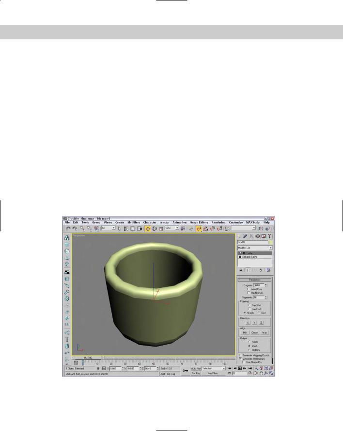
2.Select the line, and select Modifiers Patch/Spline Editing Lathe menu command. Set the Degrees value in the Parameters rollout to 360. Because you’ll lathe a full revolution, you don’t need to check the Cap options. In the Direction section, select the Y button (the Y axis), and you’re finished.
Figure 13-38 shows the finished product. You can easily make this into a coffee mug by adding a handle. To make a handle, simply loft an ellipsis along a curved path.
Bevel and Bevel Profile modifiers
Another common set of modifiers that can be used with splines and shapes are the Bevel and Bevel Profile modifiers.
Figure 13-38: Lathing a simple profile can create a circular object.

Chapter 13 Drawing and Editing 2D Splines and Shapes |
387 |
Note Both the Bevel and Bevel Profile modifiers are not found in the Modifiers menu. To apply them, use the Modifier List found in the Modifier Stack.
Using the Bevel modifier, you can extrude and outline (scale) the shape in one operation. With the Bevel modifier, you can set the Height and Outline values for up to three different bevel levels. The Capping options let you select to cap either end of the beveled shape. The Cap Type can be either Morph or Grid. The Morph type is for objects that will be morphed. You can specify that the Surface use Linear or Curved Sides with a given number of segments. You can also select to Smooth Across Levels automatically. The Keep Lines from Crossing option avoids problems that may result from crossing lines.
The Bevel Profile modifier lets you select a spline to use for the bevel profile.
Tutorial: Modeling unique rings
If you were paying attention when we discussed primitive objects, you realize that you can create a simple ring using a Tube or Torus primitive objects. If you want the ring to have a unique profile, then the Bevel and Bevel Profile modifiers are what you need.
To create a couple of unique rings with the Bevel and Bevel Profile modifiers, follow these steps:
1.Select Create Shapes Donut and drag in the Top viewport to create two donut objects that are positioned side by side. Set the Radius 1 value to 80 and the Radius 2 value to 75 for both rings.
2.Select the ring on the left in the Top viewport, open the Modify panel, and select the Bevel modifier from the Modifier List drop-down list in the Modifier Stack. In the Bevel Values rollout, set the Start Outline to 0, all Height values to 20, the Outline for Level 1 to 15, and the Outline value for Level 3 to –15. Then enable the Smooth Across Levels option.
3.Select Create Shapes Line and draw a profile curve in the Front viewport that is about the same height as the first ring.
4.Select the donut shape on the right, open the Modify panel, and choose the Bevel Profile modifier from the Modifier List in the Modifier Stack. In the Parameters rollout, click the Pick Profile button and select the profile curve.
Figure 13-39 shows the finished rings.
CrossSection modifier
The CrossSection modifier is one of two modifiers that collectively are referred to as the surface tools. The surface tools provide a way to cover a series of connected cross sections with a surface. It connects the vertices of several cross-sectional splines together with additional splines in preparation for the Surface modifier. These cross-sectional splines can have different numbers of vertices. Parameters include different spline types such as Linear, Smooth, Bézier, and Bézier Corner.
Cross-
Reference
The second half of the surface tools is the Surface modifier. You can find this modifier and an example in Chapter 15, “Creating and Editing Patches.” The surface tools are similar in many ways to the Loft compound object, which is covered in Chapter 17, “Building Compound Objects.”