

- •Preface
- •About This Book
- •Acknowledgments
- •Contents at a Glance
- •Contents
- •Relaxing at the Beach
- •Dressing the Scene
- •Animating Motion
- •Rendering the Final Animation
- •Summary
- •The Interface Elements
- •Using the Menus
- •Using the Toolbars
- •Using the Viewports
- •Using the Command Panel
- •Using the Lower Interface Bar Controls
- •Interacting with the Interface
- •Getting Help
- •Summary
- •Understanding 3D Space
- •Using the Viewport Navigation Controls
- •Configuring the Viewports
- •Working with Viewport Backgrounds
- •Summary
- •Working with Max Scene Files
- •Setting File Preferences
- •Importing and Exporting
- •Referencing External Objects
- •Using the File Utilities
- •Accessing File Information
- •Summary
- •Customizing Modify and Utility Panel Buttons
- •Working with Custom Interfaces
- •Configuring Paths
- •Selecting System Units
- •Setting Preferences
- •Summary
- •Creating Primitive Objects
- •Exploring the Primitive Object Types
- •Summary
- •Selecting Objects
- •Setting Object Properties
- •Hiding and Freezing Objects
- •Using Layers
- •Summary
- •Cloning Objects
- •Understanding Cloning Options
- •Mirroring Objects
- •Cloning over Time
- •Spacing Cloned Objects
- •Creating Arrays of Objects
- •Summary
- •Working with Groups
- •Building Assemblies
- •Building Links between Objects
- •Displaying Links and Hierarchies
- •Working with Linked Objects
- •Summary
- •Using the Schematic View Window
- •Working with Hierarchies
- •Setting Schematic View Preferences
- •Using List Views
- •Summary
- •Working with the Transformation Tools
- •Using Pivot Points
- •Using the Align Commands
- •Using Grids
- •Using Snap Options
- •Summary
- •Exploring the Modifier Stack
- •Exploring Modifier Types
- •Summary
- •Exploring the Modeling Types
- •Working with Subobjects
- •Modeling Helpers
- •Summary
- •Drawing in 2D
- •Editing Splines
- •Using Spline Modifiers
- •Summary
- •Creating Editable Mesh and Poly Objects
- •Editing Mesh Objects
- •Editing Poly Objects
- •Using Mesh Editing Modifiers
- •Summary
- •Introducing Patch Grids
- •Editing Patches
- •Using Modifiers on Patch Objects
- •Summary
- •Creating NURBS Curves and Surfaces
- •Editing NURBS
- •Working with NURBS
- •Summary
- •Morphing Objects
- •Creating Conform Objects
- •Creating a ShapeMerge Object
- •Creating a Terrain Object
- •Using the Mesher Object
- •Working with BlobMesh Objects
- •Creating a Scatter Object
- •Creating Connect Objects
- •Modeling with Boolean Objects
- •Creating a Loft Object
- •Summary
- •Understanding the Various Particle Systems
- •Creating a Particle System
- •Using the Spray and Snow Particle Systems
- •Using the Super Spray Particle System
- •Using the Blizzard Particle System
- •Using the PArray Particle System
- •Using the PCloud Particle System
- •Using Particle System Maps
- •Controlling Particles with Particle Flow
- •Summary
- •Understanding Material Properties
- •Working with the Material Editor
- •Using the Material/Map Browser
- •Using the Material/Map Navigator
- •Summary
- •Using the Standard Material
- •Using Shading Types
- •Accessing Other Parameters
- •Using External Tools
- •Summary
- •Using Compound Materials
- •Using Raytrace Materials
- •Using the Matte/Shadow Material
- •Using the DirectX 9 Shader
- •Applying Multiple Materials
- •Material Modifiers
- •Summary
- •Understanding Maps
- •Understanding Material Map Types
- •Using the Maps Rollout
- •Using the Map Path Utility
- •Using Map Instances
- •Summary
- •Mapping Modifiers
- •Using the Unwrap UVW modifier
- •Summary
- •Working with Cameras
- •Setting Camera Parameters
- •Summary
- •Using the Camera Tracker Utility
- •Summary
- •Using Multi-Pass Cameras
- •Creating Multi-Pass Camera Effects
- •Summary
- •Understanding the Basics of Lighting
- •Getting to Know the Light Types
- •Creating and Positioning Light Objects
- •Viewing a Scene from a Light
- •Altering Light Parameters
- •Working with Photometric Lights
- •Using the Sunlight and Daylight Systems
- •Using Volume Lights
- •Summary
- •Selecting Advanced Lighting
- •Using Local Advanced Lighting Settings
- •Tutorial: Excluding objects from light tracing
- •Summary
- •Understanding Radiosity
- •Using Local and Global Advanced Lighting Settings
- •Working with Advanced Lighting Materials
- •Using Lighting Analysis
- •Summary
- •Using the Time Controls
- •Working with Keys
- •Using the Track Bar
- •Viewing and Editing Key Values
- •Using the Motion Panel
- •Using Ghosting
- •Animating Objects
- •Working with Previews
- •Wiring Parameters
- •Animation Modifiers
- •Summary
- •Understanding Controller Types
- •Assigning Controllers
- •Setting Default Controllers
- •Examining the Various Controllers
- •Summary
- •Working with Expressions in Spinners
- •Understanding the Expression Controller Interface
- •Understanding Expression Elements
- •Using Expression Controllers
- •Summary
- •Learning the Track View Interface
- •Working with Keys
- •Editing Time
- •Editing Curves
- •Filtering Tracks
- •Working with Controllers
- •Synchronizing to a Sound Track
- •Summary
- •Understanding Your Character
- •Building Bodies
- •Summary
- •Building a Bones System
- •Using the Bone Tools
- •Using the Skin Modifier
- •Summary
- •Creating Characters
- •Working with Characters
- •Using Character Animation Techniques
- •Summary
- •Forward versus Inverse Kinematics
- •Creating an Inverse Kinematics System
- •Using the Various Inverse Kinematics Methods
- •Summary
- •Creating and Binding Space Warps
- •Understanding Space Warp Types
- •Combining Particle Systems with Space Warps
- •Summary
- •Understanding Dynamics
- •Using Dynamic Objects
- •Defining Dynamic Material Properties
- •Using Dynamic Space Warps
- •Using the Dynamics Utility
- •Using the Flex Modifier
- •Summary
- •Using reactor
- •Using reactor Collections
- •Creating reactor Objects
- •Calculating and Previewing a Simulation
- •Constraining Objects
- •reactor Troubleshooting
- •Summary
- •Understanding the Max Renderers
- •Previewing with ActiveShade
- •Render Parameters
- •Rendering Preferences
- •Creating VUE Files
- •Using the Rendered Frame Window
- •Using the RAM Player
- •Reviewing the Render Types
- •Using Command-Line Rendering
- •Creating Panoramic Images
- •Getting Printer Help
- •Creating an Environment
- •Summary
- •Creating Atmospheric Effects
- •Using the Fire Effect
- •Using the Fog Effect
- •Summary
- •Using Render Elements
- •Adding Render Effects
- •Creating Lens Effects
- •Using Other Render Effects
- •Summary
- •Using Raytrace Materials
- •Using a Raytrace Map
- •Enabling mental ray
- •Summary
- •Understanding Network Rendering
- •Network Requirements
- •Setting up a Network Rendering System
- •Starting the Network Rendering System
- •Configuring the Network Manager and Servers
- •Logging Errors
- •Using the Monitor
- •Setting up Batch Rendering
- •Summary
- •Compositing with Photoshop
- •Video Editing with Premiere
- •Video Compositing with After Effects
- •Introducing Combustion
- •Using Other Compositing Solutions
- •Summary
- •Completing Post-Production with the Video Post Interface
- •Working with Sequences
- •Adding and Editing Events
- •Working with Ranges
- •Working with Lens Effects Filters
- •Summary
- •What Is MAXScript?
- •MAXScript Tools
- •Setting MAXScript Preferences
- •Types of Scripts
- •Writing Your Own MAXScripts
- •Learning the Visual MAXScript Editor Interface
- •Laying Out a Rollout
- •Summary
- •Working with Plug-Ins
- •Locating Plug-Ins
- •Summary
- •Low-Res Modeling
- •Using Channels
- •Using Vertex Colors
- •Rendering to a Texture
- •Summary
- •Max and Architecture
- •Using AEC Objects
- •Using Architectural materials
- •Summary
- •Tutorial: Creating Icy Geometry with BlobMesh
- •Tutorial: Using Caustic Photons to Create a Disco Ball
- •Summary
- •mental ray Rendering System
- •Particle Flow
- •reactor 2.0
- •Schematic View
- •BlobMesh
- •Spline and Patch Features
- •Import and Export
- •Shell Modifier
- •Vertex Paint and Channel Info
- •Architectural Primitives and Materials
- •Minor Improvements
- •Choosing an Operating System
- •Hardware Requirements
- •Installing 3ds max 6
- •Authorizing the Software
- •Setting the Display Driver
- •Updating Max
- •Moving Max to Another Computer
- •Using Keyboard Shortcuts
- •Using the Hotkey Map
- •Main Interface Shortcuts
- •Dialog Box Shortcuts
- •Miscellaneous Shortcuts
- •System Requirements
- •Using the CDs with Windows
- •What’s on the CDs
- •Troubleshooting
- •Index

Chapter 20 Creating Simple Materials 573
2.Open the Material Editor by choosing Rendering Material Editor, by clicking the Material Editor button on the main toolbar, or by pressing the M key.
3.In the Material Editor, select the first sample slot; in the Name field, name the material Curtains. Select the Translucent Shader from the Shader Basic Parameters rollout. Click the Diffuse color swatch, and select a light blue color. Click the Close button to exit the Color Selector.
4.Click the Translucent Color swatch, change its color to a light gray, and set the Opacity to 75.
5.Drag the Curtains material onto the curtain object in the Left viewport.
Figure 20-10 shows the resulting image. Notice that the tree’s shadow is being cast on the curtains.
Figure 20-10: These translucent window curtains show shadows.
Accessing Other Parameters
In addition to the basic shader parameters, several other rollouts of options can add to the look of a material.
Extended Parameters rollout
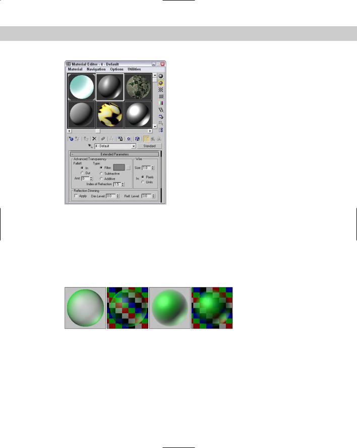
In addition to the Basic Parameters, the Material Editor includes several more settings that are common for most shaders. The Extended Parameters rollout, shown in Figure 20-11, includes Advanced Transparency, Reflection Dimming, and Wire controls. All shaders include these parameters.
574 Part IV Materials and Maps
Figure 20-11: The Extended Parameters rollout includes Advanced Transparency, Reflection Dimming, and Wire settings.
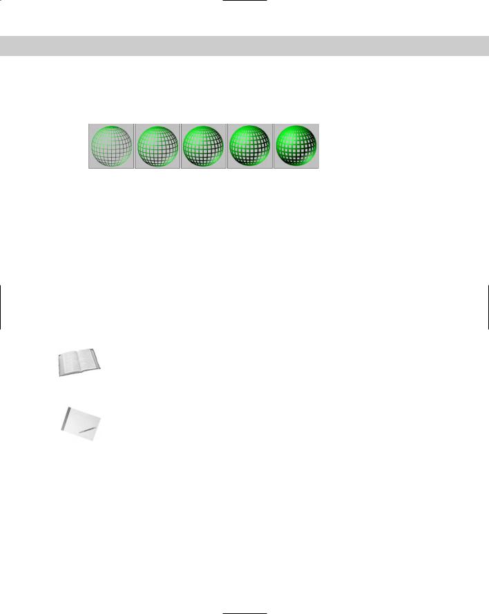
You can use the Advanced Transparency controls to set the Falloff to be In, Out, or a specified Amount. The In option increases the transparency as you get farther inside the object, and the Out option does the opposite. The Amount value sets the transparency for the inner or outer edge. Figure 20-12 shows two materials that use the Transparency Falloff options on a gray background and on a patterned background. The two materials on the left use the In option, and the two on the right use the Out option. Both are set at Amount values of 100.
Figure 20-12: Materials with the In and Out Falloff options applied
The three transparency types are Filter, Subtractive, and Additive. The Filter type multiples the Filter color with any color surface that appears behind the transparent object. With this option, you can select a Filter color to use. The Subtractive and Additive types subtract from or add to the color behind the transparent object.
The Index of Refraction is a measure of the amount of distortion caused by light passing through a transparent object. Different physical materials have different Index of Refraction values. The amount of distortion also depends on the thickness of the transparent object. The Index of Refraction for water is 1.33 and for glass is 1.5. The default of 1.0 has no effect.
Chapter 20 Creating Simple Materials 575
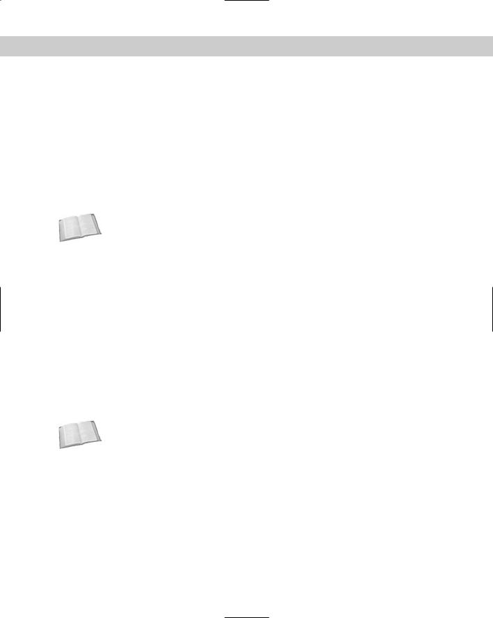
The Wire section lets you specify a wire size or thickness. Use this setting if the Wire mode is enabled in the Shaders rollout. The size can be measured in either Pixels or Units. Figure 20-13 shows materials with different Wire values from 1 to 5 pixels.
Figure 20-13: Three materials with Wire values of (from left to right) 1, 2, 3, 4, and 5 pixels
Reflection Dimming controls how intense a reflection is. You enable it by using the Apply option. The Dim Level setting controls the intensity of the reflection within a shadow, and the Refl Level sets the intensity for all reflections not in the shadow.
SuperSampling rollout
Pixels are small square dots that collectively make up the entire screen. At the edges of objects where the material color changes from the object to the background, these square pixels can cause jagged edges to appear. These edges are called artifacts and can ruin an image. Anti-aliasing is the process through which these artifacts are removed by softening the transition between colors.
Max includes anti-aliasing filters as part of the rendering process. SuperSampling is an additional anti-aliasing pass that can improve image quality that is applied at the material level. You have several SuperSampling methods from which to choose.
Cross- |
For more about the various anti-aliasing filters, see Chapter 41, “Rendering Basics.” |
Reference |
|
SuperSampling is calculated only if the Anti-Aliasing option in the Render Scene dialog box is enabled. The raytrace material type has its own SuperSampling pass and doesn’t need SuperSampling enabled.
Note |
Using SuperSampling can greatly increase the time it takes to render an image. |
In a SuperSampling pass, the colors at different points around the center of a pixel are sampled. These samples are then used to compute the final color of each pixel. These four SuperSampling methods are available:
Adaptive Halton: Takes semi-random samples along both the pixel’s X-axis and Y-axis. It can take from 4 to 40 samples.
Adaptive Uniform: Takes samples at regular intervals around the pixel’s center. It takes from 4 to 26 samples.
Hammersley: Takes samples at regular intervals along the X-axis, but takes random samples along the Y-axis. It takes from 4 to 40 samples.
Max 2.5 Star: Takes four samples along each axis.
576 Part IV Materials and Maps
The first three methods enable you to select a Quality setting. This setting specifies the number of samples to be taken. The more samples taken, the higher the resolution, but the longer it takes to render. The two Adaptive methods (Adaptive Halton and Adaptive Uniform) offer an Adaptive option with a Threshold spinner. This option takes more samples if the change in color is within the Threshold value. The SuperSample Texture option includes maps in the SuperSampling process along with materials.
Maps rollout
A map is a bitmap image that is pasted on an image. The Maps rollout includes a list of the maps that you can apply to an object. Using this rollout, you can enable or disable maps, specify the intensity of the map in the Amount field, and load maps. Clicking the Map buttons opens the Material/Map Browser where you can select the map type.
Cross- |
Find out more about maps in Chapter 22, “Adding Material Details with Maps.” |
Reference |
|
Dynamic Properties rollout
The properties in the Dynamic Properties rollout are used along with the Dynamics utility in simulations. These properties define how the object is animated during collisions. If these properties are not specified for an object, then the default material settings, which are similar to steel, are used.
The Dynamic Properties rollout includes only the following three values:
Cross-
Reference
Bounce Coefficient: Determines how high an object bounces after a collision. The default of 1.0 is equal to a normal elastic collision. A ball with a value greater than 1, for example, continues to bounce higher with each impact.
Static Friction: Determines how difficult it is to start an object moving when pushed across a surface. Objects with high Static Friction values require lots of force to move.
Sliding Friction: Determines how difficult it is to keep an object in motion across a surface. Ice, for example, has a low Sliding Friction value, because after it starts moving, it continues easily.
For more information on dynamic simulations, check out Chapter 39, “Creating a Dynamic Simulation.”
mental ray connection rollout
The mental ray connection rollout includes options for enabling different properties that are used by the mental ray rendering engine. The properties include Surface and Shadow Shaders, Photon and Photon Volume, and Extended Shaders and Advanced Shaders, including Contour and Light Map.

Chapter 20 Creating Simple Materials 577
Cross- |
The mental ray rendering engine and its properties are covered in Chapter 44, “Raytracing |
Reference |
and mental ray.” |
|
Tutorial: Coloring a dolphin
As a quick example of applying materials, we take a dolphin model created by Zygote Media and position it over a watery plane. We then apply custom materials to both objects.
To add materials to a dolphin, follow these steps:
1.Open the Dolphin.max file from the Chap 20 directory on the CD-ROM. This file contains a simple plane object and a dolphin mesh.
2.Open the Material Editor by choosing Rendering Material Editor, clicking the Material Editor button on the main toolbar, or pressing the M key.
3.In the Material Editor, select the first sample slot; in the Name field (to the right of the Pick Material from Object button), rename the material Dolphin Skin. Click the Diffuse color swatch, and select a light gray color. Then click the Specular color swatch, and select a light yellow color. Click the Close button to exit the Color Selector. In the Specular Highlights section, increase the Specular Level to 45.
4.Drag the Dolphin Skin material from the first sample slot to the second sample slot, and name it Ocean Surface. Click the Diffuse color swatch, and select a light blue color. Set the Specular Level and Opacity values to 80. In the Maps rollout, click the None button to the right of the Bump selection. In the Material/Map Browser that opens, doubleclick the Noise selection.
5.Drag the Ocean Surface material onto the plane object in the Top viewport. Then drag the Dolphin Skin material onto the dolphin model.
Note This model also includes separate objects for the eyes, mouth, and tongue. These objects could have different materials applied to them, but they are so small in this image that we won’t worry about them.
6.Choose Rendering Environment (keyboard shortcut, 8), click the Background Color swatch, and change it to a light sky blue.
Figure 20-14 shows the resulting image.