

288 Part II Working with Objects
Cross- In the Align button flyout are two other common ways to align objects: Align Camera and Reference Place Highlight (Ctrl+H). To learn about these features, see Chapter 24, “Working with
Cameras,” and Chapter 27, “Basic Lighting Techniques,” respectively.
Aligning to a view
The Align to View command provides an easy and quick way to reposition objects to one of the axes. To use this command, select an object and then choose Tools Align to
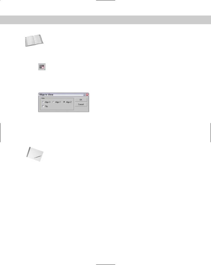
View. The Align to View dialog box appears, as shown in Figure 10-14. Changing the settings in this dialog box displays the results in the viewports. You can use the Flip command for altering the direction of the object points. If no object is selected, then the Align to View command cannot be used.
Figure 10-14: The Align to View dialog box is a quick way to line up objects with the axes.
The Align to View command is especially useful for fixing the orientation of objects when you create them in the wrong view. All alignments are completed relative to the object’s Local Coordinate System. If several objects are selected, each object is reoriented according to its Local Coordinate System.
Note Using the Align to View command on symmetrical objects like spheres doesn’t produce any noticeable difference in the viewports.
Using Grids
When Max is started, the one element that is visible is the Home Grid. This grid is there to give you a reference point for creating objects in 3D space. At the center of each grid are two darker lines. These lines meet at the origin point for the World Coordinate System where the coordinates for X, Y, and Z are all 0.0. This point is where all objects are placed by default.
In addition to the Home Grid, you can create and place new grids in the scene. These grids are not rendered, but you can use them to help you locate and align objects in 3D space.
The Home Grid
You can turn the Home Grid on or off by choosing Views Grid Show Home Grid (you can also turn the Home Grid on and off for the selected viewport using the G key). If the Home

Chapter 10 Transforming Objects—Translate, Rotate, and Scale |
289 |
Grid is the only grid in the scene, then by default it is also the construction grid where new objects are positioned when created.
You can access the Home Grid parameters (shown in Figure 10-15) by choosing Customize Grid and Snap Settings. You can also access this dialog box by right-clicking the Snap, Angle Snap, or Percent Snap Toggle buttons located on the main toolbar.
In the Home Grid panel of the Grid and Snap Settings dialog box, you can set how often Major Lines appear, as well as Grid Spacing. (The Spacing value for the active grid is displayed on the status bar.) You can also specify to dynamically update the grid view in all viewports or just in the active one.
The User Grids panel lets you activate any new grids when created.
Figure 10-15: The Home Grid and User Grids panels of the Grid and Snap Settings dialog box let you define the grid spacing.
Creating and activating new grids
In addition to the Home Grid, you can create new grids. To create a new Grid object, select the Create Helpers Grid menu command or open the Create panel, select the Helpers category, and click the Grid button. In the Parameters rollout are settings for specifying the new grid object’s dimensions, spacing, and color, as well as which coordinate plane to display (XY, YZ, or ZX).
You can designate any newly created grid as the default active grid. To activate a grid, make sure that it is selected and choose Views Grids Activate Grid Object. Keep in mind that only one grid may be active at a time, and the default Home Grid cannot be selected. You can also activate a grid by right-clicking the grid object and selecting Activate Grid from the popup menu. To deactivate the new grid and reactivate the Home Grid, choose Views Grids Activate Home Grid, or right-click the grid object and choose Activate Grid Home Grid from the pop-up quadmenu.
You can find further grid settings for new grids in the Grid and Snap Settings dialog box on the User Grids panel. The settings include automatically activating the grid when created and an option for aligning an AutoGrid using World space or Object space coordinates.
290 Part II Working with Objects
Using AutoGrid
You can use the AutoGrid feature to create a new construction plane perpendicular to a face normal. This feature provides an easy way to create and align objects directly next to one another without manually lining them up or using the Align features.
The AutoGrid feature shows up as a check box at the top of the Object Type rollout for every category in the Create panel. It becomes active only when you’re in Create Object mode.
To use AutoGrid, click the AutoGrid option after selecting an object type to create. If no objects are in the scene, then the object is created as usual. If an object is in the scene, then the cursor moves around on the surface of the object with its coordinate axes perpendicular to the surface that the cursor is over. Clicking and dragging creates the new object based on the precise location of the object under the mouse.
The AutoGrid option stays active for all new objects that you create until you turn it off by unchecking the box.
Tip Holding down the Alt key before creating the object makes the AutoGrid permanent and active.
Tutorial: Creating a Spyglass
As you begin to build objects for an existing scene, you find that working away from the scene origin is much easier if you enable the AutoGrid feature for the new objects you create. This feature enables you to position the new objects on (or close to) the surfaces of the nearby objects). It works best with objects that have pivot points located at their edges, such as Box and Cylinder objects.
In this example, you quickly create a spyglass object using the AutoGrid without needing to perform additional moves.
To create a spyglass using the AutoGrid and Snap features, follow these steps.
1.Before starting, click the Left viewport and zoom way out so you can see the height of the spyglass pieces.
2.Select Create Standard Primitives Cylinder and drag from the origin in the Top viewport to create a Cylinder object. Set the Radius value to 40 and the Height value to 200. Then enable the AutoGrid option in the Object Type rollout.
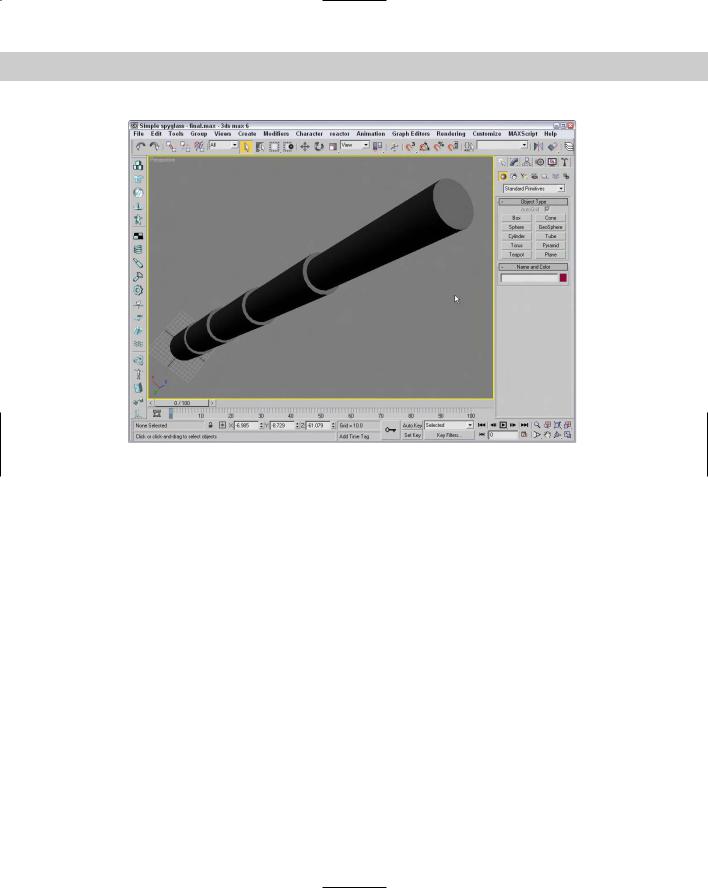
3.Drag from the origin again in the Top viewport to create another Cylinder object. Set its Radius to 35 and its Height to 200. Repeat this step three times, reducing the Radius by 5 each time.
Figure 10-16 shows the resulting spyglass object.
Chapter 10 Transforming Objects—Translate, Rotate, and Scale |
291 |
Figure 10-16: This spyglass object was created quickly and easily using the
AutoGrid option.
Using Snap Options
Often when an object is being transformed, you know exactly where you want to put it. The Snap feature can be the means whereby objects get to the precise place they should be. For example, if you are constructing a set of stairs from box primitives, you can enable the edge snap feature to make each adjacent step be aligned precisely along the edge of the previous step. With the snap feature enabled, an object automatically moves (or snaps) to the specified snap position when you place it close enough. If you enable the Snap features, they affect any transformations that you make in a scene.
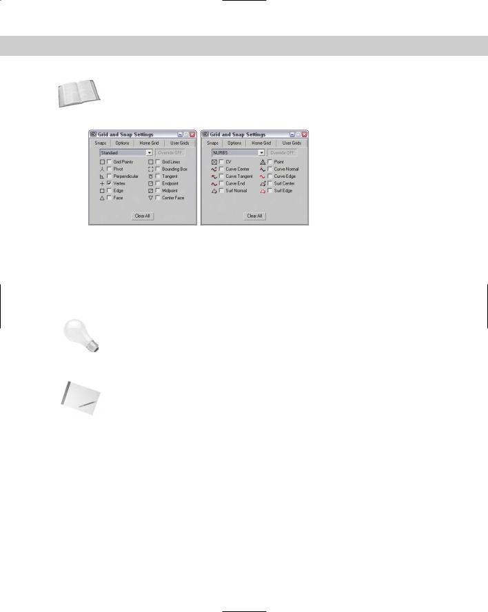
Snap points are defined in the Grid and Snap Settings dialog box that you can open by choosing Customize Grid and Snap Settings or by right-clicking any of the first three Snap buttons on the main toolbar (these Snap buttons have a small magnet icon in them). Figure 10-17 shows the Snaps panel of the Grid and Snap Settings dialog box for Standard and NURBS objects. NURBS stands for Non-Uniform Rational B-Splines. They are a special type of object created from spline curves.
292 Part II Working with Objects
Cross- In addition to the snap points for standard objects, the Snaps panel also includes a list of Reference snap points for NURBS objects. For more information on NURBS, see Chapter 16, “Working
with NURBS.”
|
Figure 10-17: The Snaps panel includes many different points |
|
to snap to depending on the object type. |
|
After snap points have been defined, the Snap buttons on the main toolbar activate the Snaps |
|
feature. The first Snaps button consists of a flyout with three buttons: 3D Snap Toggle, 2.5D |
|
Snap Toggle, and 2D Snap Toggle. The 2D Snap Toggle button limits all snaps to the active |
|
construction grid. The 2.5D Snap Toggle button snaps to points on the construction grid as |
|
well as projected points from objects in the scene. The 3D Snap Toggle button can snap to |
|
any points in 3D space. |
Tip |
Right-clicking the snap toggles opens the Grid and Snap Settings dialog box, except for the |
|
Spinner Snap Toggle, which opens the Preference Settings dialog box. |
|
These Snap buttons control the snapping for translations. To the right are two other buttons: |
|
Angle Snap Toggle and Percent Snap. These buttons control the snapping of rotations and |
|
scalings. |
Note |
The keyboard shortcut for turning the Snaps feature on and off is the S key. |
|
With the Snaps feature enabled, the cursor becomes blue crosshairs wherever a snap point is |
|
located. |
|
Setting snap points |
|
The Snap tab in the Grid and Snap Settings dialog box has many points that can be snapped |
|
to in two categories: Standard and NURBS. The Standard snap points (previously shown in |
|
Figure 10-17) include the following: |
Grid Points: Snaps to the Grid intersection points
Grid Lines: Snaps only to positions located on the Grid lines

Chapter 10 Transforming Objects—Translate, Rotate, and Scale |
293 |
Pivot: Snaps to an object’s pivot point
Bounding Box: Snaps to one of the corners of a bounding box
Perpendicular: Snaps to a spline’s next perpendicular point
Tangent: Snaps to a spline’s next tangent point
Vertex: Snaps to polygon vertices
Endpoint: Snaps to a spline’s end point or the end of a polygon edge
Edge: Snaps to positions only on an edge
Midpoint: Snaps to a spline’s midpoint or the middle of a polygon edge
Face: Snaps to any point on the surface of a face
Center Face: Snaps to the center of a face
Several snap points specific to NURBS objects, such as NURBS points and curves, are also shown in Figure 10-16. These points include
CV: Snaps to any NURBS Control Vertex subobject
Point: Snaps to a NURBS point
Curve Center: Snaps to the center of the NURBS curve
Curve Normal: Snaps to a point that is normal to a NURBS curve
Curve Tangent: Snaps to a point that is tangent to a NURBS curve
Curve Edge: Snaps to the edge of a NURBS curve
Curve End: Snaps to the end of a NURBS curve
Surf Center: Snaps to the center of a NURBS surface
Surf Normal: Snaps to a point that is normal to a NURBS surface
Surf Edge: Snaps to the edge of a NURBS surface
Setting snap options
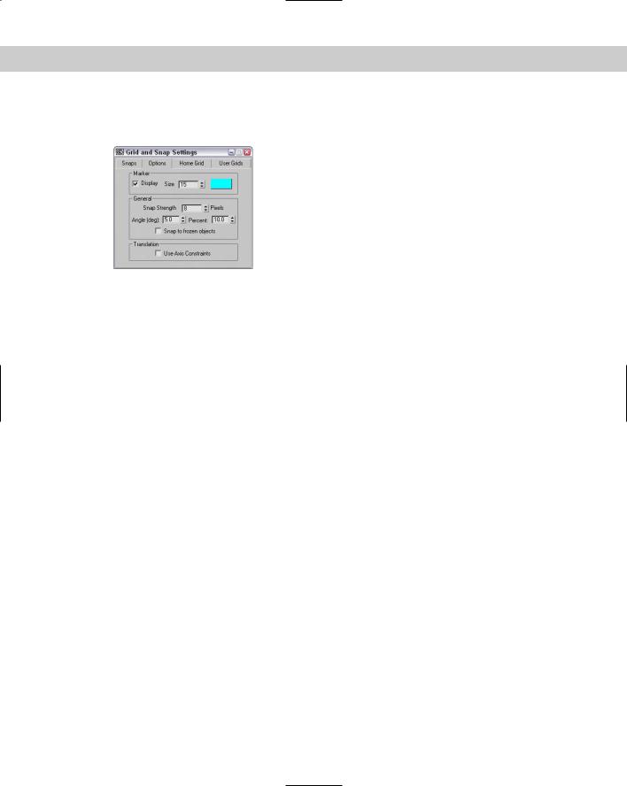
The Grid and Snap Settings dialog box holds a panel of Options, shown in Figure 10-18, in which you can set whether or not markers display, the size of the markers, and their color. If you click the color swatch, a Color Selector dialog box opens and enables you to select a new color. The Snap Strength setting determines how close the cursor must be to a snap point before it snaps to it. The Angle and Percent values are the strengths for any rotate and scale transformations, respectively. You can also cause translations to be affected by the designated axis constraints with the Use Axis Constraints option.
Within any viewpoint, holding down the Shift key and right-clicking in the viewport can access a pop-up menu of grid points and options. This pop-up quadmenu lets you quickly add
294 Part II Working with Objects
or reset all the current snap points and change snap options, such as Transformed Constraints and Snap to Frozen.
Figure 10-18: The Options panel includes settings for marker size and color and the Snap Strength value.
Tutorial: Creating a lattice for a methane molecule
Many molecules are represented by a lattice of spheres. Trying to line up the exact positions of the spheres by hand could be extremely frustrating, but using the Snap feature makes this challenge, well . . . a snap.
One of the simpler molecules is methane, which is composed of one carbon atom surrounded by four smaller hydrogen atoms. To reproduce this molecule as a lattice, we first need to create a tetrahedron primitive and snap spheres to each of its corners.
To create a lattice of the methane molecule, follow these steps:
1.Right-click the Snap Toggle button in the main toolbar to open the Grid and Snap Settings, and enable the Grid Points and Vertex options. Then click the Snap Toggle button (or press the S key) to enable 3D Snap mode.
2.Select the Create Extended Primitives Hedra menu command, set the P Family Parameter to 1.0, and drag in the Top viewport from the center of the Home Grid to the first grid point to the right to create a Tetrahedron shape.
3.Click and hold the Snap toggle button, and select the 3D Snap flyout option. Select the Create Standard Primitives Sphere menu command. Right-click in the Left viewport, and drag from the top left vertex to create a sphere. Set the sphere’s Radius to 25.
4.Create three more sphere objects with Radius values of 25 that are snapped to the vertices of the Tetrahedron object.
5.Finally, create a sphere in the Top viewport using the same snap point as the initial tetrahedron. Set its Radius to 80.
Figure 10-19 shows the finished methane molecule.